

proxlamus©
-
Posts
2145 -
Joined
-
Last visited
-
Days Won
1
Content Type
Profiles
Forums
Blogs
Events
Gallery
Downloads
Store
Posts posted by proxlamus©
-
-
Ok.. after about 2 horus of research LoL..
I have come to the conclusion...
This is from the FSM :
--------------------------------
"When the flap deflects along with a change in the intake air flow rate, the terminal (PIN 7) mounted to the flap shaft slides on the variable resistor R from R1 to R9, causing the voltage across terminals (PIN 7 and PIN 8 ) to change.
A constant voltage Ub (battery volts) is applied across terminals (PIN 6 and PIN 9). Then the air flow rate is converted with the voltage ratio signal U/Ub, which in turn is sent to the control unit for computation."
---------------------------------
The applied voltage the AFM sends to the ECU is U/Ub .. basically the voltage ratio signal the ECU needs to control the fuel with the air ratio.
HOWEVER.. the FSM fails to state what PIN or what wire the signal is sent out of!!! Pain in the ***.. grr
anyway.. after the graph/chart research..
This means..
That PIN 7 is the "output" signal of the U/Ub voltage ratio signal...
Hence.. as the RPM's increase.. the "voltage ratio signal" decreases...
RPM Vu/Vub 7
3000 0.139 5.048
4000 0.122 5.220
5000 0.111 5.328
6000 0.104 5.403
7000 0.098 5.460

Doesn't this make sense or no??!
Anyone care to verify?
-
Ok guys... blah blah blah I am tryn to figure out this S-AFC thinggy...
Anyway... I need the AFM signal wire to the ECU... and I can't figure it out...
which "pin" or wire tells the ECU what the air ratio is??
I copied this from BLUE's atlanta Z tech tips page...
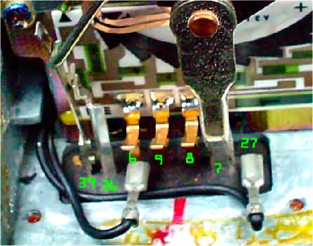
6. AFM Measurements taken on a 77 280z referenced to chassis ground.
test
point 39 36 6 9 8 7 27 Vreg temp
rpm
800 13.93 13.93 0.01 11.59 7.48 3.22 5.09 14.04 6
1000 13.92 13.92 0.01 11.64 7.52 4.14 5.14 14.08 6
1200 13.98 13.98 0.01 11.7 7.56 4.68 5.23 14.15 6
1400 14.03 14.03 0.01 11.76 7.59 4.99 5.21 14.18 6
1600 14.35 14.35 0.01 12.06 7.78 5.41 5.25 14.49 6
2300 14.32 14.32 0.01 12.05 7.75 5.82 5.25 14.45 6
Normalized data (to 12V standard) from above table
test point
39 36 6 9 8 7 27 Vreg temp
rpm
800 11.91 11.91 0.01 9.91 6.39 2.75 4.35 12.00 6
1000 11.86 11.86 0.01 9.92 6.42 3.53 4.38 12.00 6
1200 11.86 11.86 0.01 9.92 6.41 3.97 4.44 12.00 6
1400 11.87 11.87 0.01 9.95 6.42 4.22 4.41 12.00 6
1600 11.88 11.88 0.01 9.99 6.44 4.48 4.35 12.00 6
2300 11.89 11.89 0.01 10.01 6.44 4.83 4.36 12.00 6
The ECU sends a voltage ratio to the ECU. The ratio is U/Ub as per the schematic below.
V Ref Resistance
(9-8) Vu (8-7) Vub (9-6) Vu/Vub
3.51 3.64 9.90 0.37
3.51 2.88 9.91 0.29
3.51 2.44 9.91 0.25
3.53 2.20 9.94 0.22
3.54 1.96 9.98 0.20
3.57 1.60 10.00 0.16
The following model shows Vu/Vub vs RPM
Harris Model: y=1/(a+bx^c)
Coefficient Data:
a = -62.727835
b = 46.860151
c = 0.049964787
Applying the model to other rpms yields (normalized and assuming Vub=10 and Vpin9=10):
RPM Vu/Vub 7
3000 0.139 5.048
4000 0.122 5.220
5000 0.111 5.328
6000 0.104 5.403
7000 0.098 5.460
OK.. so I narrowed everything down to at least PIN 6 which is what I was going to hook the S-AFC (super air flow converter) up to..
But then I noticed that PIN 6 has a 0.01 voltage almost straight across the board.. while PIN 7 flucuates...
Is the "main" signal from the AFM to the ECU PIN 6 or PIN 7 ??
Pin 27... is the temp sensor
-
I scanned the Apexi S-AFC manual's diagram, and wrote next to each connection what ECU PIN and what color the wire should be.
I also scanned the 1978 FSM for a diagram of what our car really has, compared to the overly simplified Apexi S-AFC diagram.
What I discovered is.. the Throttle Signal or TPS basically connects to 3 PINS on the ECU...
IDLE - Pin 2 and Pin 18 (black wire)
FULL THROTTLE - Pin 3 and Pin 18 (black wire)
and the Air Flow signal or AFM connects to 4 PINS.. *sigh*
Pin 6 and Pin 8 (black wire)
Pin 7 and Pin 8 (black wire)
Pin 8 and Pin 9 (black wire)
This is obviously a problem, because the Apexi S-AFC only has the TPS and AFM signal connected to one wire.. not 3 or 4 for each one!!!
Anyway.. can anyone give me a good idea on which wires I should connect this to.. to get it running??
-
Apexi S-AFC install.. I am getting close.. just need some help
As you guys may or may not know, I am attempting to install this Apexi SAFC to work on our older Z cars with the factory ECU.. and here is where I am stuck..
here is a thread with tons of info about it.. and stuff
http://forums.hybridz.org/showthread.php?t=87665
http://www.zcar.com/forums/read.php?f=1&i=558520&t=558520
Anyway.. I scanned the Apexi S-AFC manual's diagram, and wrote next to each connection what ECU PIN and what color the wire should be.
I also scanned the 1978 FSM for a diagram of what our car really has, compared to the overly simplified Apexi S-AFC diagram.
What I discovered is.. the Throttle Signal or TPS basically connects to 3 PINS on the ECU...
IDLE - Pin 2 and Pin 18 (black wire)
FULL THROTTLE - Pin 3 and Pin 18 (black wire)
and the Air Flow signal or AFM connects to 4 PINS.. *sigh*
Pin 6 and Pin 8 (black wire)
Pin 7 and Pin 8 (black wire)
Pin 8 and Pin 9 (black wire)
This is obviously a problem, because the Apexi S-AFC only has the TPS and AFM signal connected to one wire.. not 3 or 4 for each one!!!
Anyway.. can anyone give me a good idea on which wires I should connect this to.. to get it running??
-
OK.. sorry about all these posts...
I was reading my FSM.. and I noticed that the stock AFM has 2 wires coming out/in.
One is a Air Temperature Sensor
One is a POTENTIOMETER ... which is exactly what the 240SX TB has.. a potentiometer so send the signal how open or closed the throttle is.
Now if the AFM has a potentiometer.. instead of hooking the SAFC to the throttle and the TPS... why not the potentiometer on the AFM?
NOTE : A potentiometer expresses the angle of rotation of the flap, monitored by a potentiometer inside the AFM....
-
K... the TPS has 3 wires...
I THINK this is how it goes.. but then again I just read this post
RED - Positive (Power)
BLACK - Negative (Ground)
WHITE - Sends the signal to the ECU....
----------------------
quote :
tanza/240sx tps forever now, with the extra pins for the variable load. the three pin that goes on that matches the original tps pin is what i use for eccs harness. The black connector off the tps is all you need for eccs, effectively making it a TVS-on off switch. the grey pin connector is what gives signal to variable load. since my ecu knows nothing about that load signal, i connected it directly to the afr, and the box reads load, while eccs gets on and off.
----------------------
or is it ?
Black - Turns ECCS on/off
Red - to my ignition?
Grey/White - Sends load signal to the SAFC
?????
So I guess I hook up the black connector? or the Grey/white?? *sigh*
Do I need to power the TPS for it to send the signal? Ohh yeh.. guess that's where the 0-5 volts come from correct??! I'll hook it up to the ignition i suppose.
OK.. so TPS is figured out.. now for the Tach...
Since I am running the stock ignition and electronics... and getting an MSD 6A would be out of my price range right now... could I simply get a TACHOMETER adapter?
-------------------------------------
Keep your tachometer honest.
Tach Adapter, Magnetic Pickup Ignition Systems, Each
If you are using the magnetic pickup input (green and violet wires) to trigger your MSD Ignition, you will need one of these tach adapters. These units will correct the operation of most voltage-triggered tachometers that do not work directly off of the tach output terminal of your MSD unit.
--------------------------------------
Now if I get this TACH adapter.. I can still run the stock tachometer without problems right?!
-
So someting like this??
------------------------------------------
Map Sensor, Bosch Style, 2 Bar, Each
The pressure inside your intake manifold is extremely important input to the ECU. A quality MAP sensor like MSD's is crucial to your engines performance. These sensors will respond to changes in manifold pressures and relay the information to the ECU in the form of a voltage signal ranging from about 1 to 5 volts. They're available in several different versions for naturally aspirated engines as well as engines with forced induction.
-------------------------------------------
Ok.. so I can get an MAP sensor.. however.. how would the SAFC tell the difference between the TPS and/or the MAP??
Obviously the SAFC monitors how open or closed the throttle is.. for example the throttle is 38% open, and adds in a certain amount of fuel...
But the MAP just monitors the manifold pressure.. soo.. could this tell how open/closed the throttle is?
There is a setting on the SAFC which you can monitor the Throttle.. which tells you the percent it is open (38% example) .. would the MAP do the same?
-
Alright... ran into a problem...
How do I wire the extra wires on the 240sx 60mm TB??
There is a pig-tail with 3 wires.... now.. how exactly do I wire this up to the Apexi SAFC for it to read the TPS? Should I extend a wire all the way across the engine bay, and connect it directly to the Apexi's TPS wire?
-
you could always get a much longer pipe for the intake on the turbo...
hell you could even go crazy and make custom vents on the rear quaters like Supra's have.. or even like the Ferrari's
and put a bend pipe up there and put the filter behind the vent.. this would mean.. no water puddles -
Well I just picked up a digital Apexi S-AFC and a DSM BOV today with a flange for only $150 for everything! Not bad! and the guy brought it to me at school..
Anyway.. I will begin swapping everything in, and taking pictures... and documenting everything.. so I will be able to let EVERYONE know how it works out.. and if in fact.. I can USE IT!
Anyone have any good recommendations?!?! I will begin next week =)
-
Yeh.. any idea's on cost??
I would love to buy a "pre-made" setup witha re-tuned ECU and a harness.. would save alot of time and frustration!!
I am interested.. shoot me an e-mail
-
I wouldn't mind a copy!!
Would ya be able to send one to me?!
Thanks!
proclamus @ hotmail . com
Without the spaces.. damn spam scanners
-
ohh man that sucks.. im sorry to hear that..
-
.50 trim is nearly ideal for our Z cars.. observe
Air Flow Data Plotted Against Different Boost Levels and Transcribed to Garrett T04E-50 Compressor Map (Pressure Ratio vs. lbs/min)
* 6500 rpm red line points for this compressor at all three level of boost are in the 75% +/- 1% efficiency region.
* 3250 rpm "knee" points for this compressor at all three level of boost are in the 74% +/- 1% efficiency region.
* When accelerating towards redline, the efficiency passes through the maximum 78% area, thus performance is ideal during this period.
* It should be obvious that this compressor can handle even more boost and remain very efficient above the 20psi line. "It can grow with your need for more speed"
* This compressor will give great performance compared to the stock T3-60.
* Goldilocks says "just right"
This is the 60 trim exhuast housing...
Air Flow Data Plotted Against Different Boost Levels and Transcribed to Garrett T04B-60-1 Compressor Map (Pressure Ratio vs. lbs/min)
* 6500 rpm red line points for this compressor all fail to reach the highest efficiency region.
* 3250 rpm "knee" points for this compressor at all three levels of boost are in the surge threshold region
* It should be obvious that this compressor will work better with a larger displacement engine as it's sweet spot is far to the right where higher flows are required.
* Goldilocks says "too demanding"
-
-------------------------------------
Quote : Apexi-usa.com
The Super AVC-R is the premium closed-loop electronic boost controller on the market. The AVC-R allows flexible control over virtually every aspect of boost control and adds new innovative functions such as injector pulse monitoring and gear specific boost control. Some key functions include: RPM-based boost and solenoid duty cycle control, scramble boost, self learning mode, 2D ghost map trace mode, analog display mode, real time replay and peak hold data modes. The AVC-R utilizes an ultra-fast microprocessor and a high quality solenoid valve to control boost. The result is ultra-fast response and accurate, stable boost control.
---------------------------------
-
Exhuast backfire is a RICH condition
Intake backfire and stuttering is a LEAN condition
-
-
How much boost are you planning on running??
The Turbo fuel pump will supply enough fuel for about 12 psi of boost.. roughly.. before it starts to lean out...
You will need about 80psi of fuel for 10 pounds of boost.
but.. with an N/A block and head.. your compression will be a bit high... so unless you have 93 octane... and ZXT injectors you will have detonation and pinging...
BTW - RRFPR are the same as FMU's (fuel management unit) but it should be plenty.
Here's an e-mail I got from a very nice gentleman Dan...
----------------------------
I would recommend finding a P90 head. You will have detonation problems with the N47 over 6 psi of boost.
The fuel pump system is very important when using a FMU. I have been fine tuning my setup over the past year. I found it is best to use a Mallory comp110 low pressure pump to feed two stock type efi pumps in parallel. Here is a photo of my twin pump setup. Of course there is a Mallory low pressure pump by the gas tank feeding the two efi pumps in the engine compartment. I relocated the fuseable links to under the mounting plate and used a relay to power the pumps. I cut off the wire from the fuseable link connectors and used fuseable link wire and crimp connectors to complete the circuit.
I’m using msd pumps which cost about 100.00 each. I run about 90 psi for 12 psi of boost and 100 psi for 14 to 15 psi on the NA stock injectors. 60 psi is good for 6-8 psi of boost with NA injectors.
I’m using the stock FPR and a bell engineering fmu and stock NA efi computer.
I disassembled the distributor and welded the advance slot in the so that I get only 8 degrees of advance. I set the timing to 20 initial (28 total) and use the vacuum advance. The vacuum advance is great for gas mileage because it adds 10 to 15 degrees during no boost conditions.
I use 93 octane but can get by with 91 if I retard the initial timing 3 degrees.
I liked the straight T3 turbo better than the t3/t4 for street performance. The t3 made 5 psi of boost by 2200 rpm and full boost by 2800 rpm! The t3/t4 only makes 5 psi at 3000 and full boost by 3500. The low rpm torque of the t3 was great and fun to drive! Rolling on the throttle in low rpms in 3rd gear and getting wheel spin is fun.
I’m using the t3/t04b-h3 wheel turbo. The t04b turbo doesn’t require a spacer like the t04e.
No need for a IC if you are running less than 10 psi of boost. I know the dynos show big improvements with an IC but it is not that apparent in the “pant seat dynoâ€.
You will need a 2+2 clutch (240mm)! The stock clutch will hold 10 psi of boost. After that you will need a spec stage 2. The spec stage 3 sucks on the street but is very tough.
This system works for me but the cost of the three pumps (370.00) and the fmu (200.00) is about the cost of a “stand alone†efi system.
You need a fuel and boost pressure gage in order to tune correctly. I put a boost gage in the clock location and a fuel pressure gage on the pillar.
Walbro pumps are loud! Your whole entire car will vibrate!
My g-tech says my 78 280 NA car is making 130 hp, so we are close. But the turbo car is doubling that at 15 psi!
Use the formula (boost+14.7)/14.7 to get the hp multiplier form a turbo. So 10 psi would give you: (10+14.7)/14.7=1.68,
1.68 x 135hp (you current NA hp) = 226 hp.
I would just do a simple turbo install first then do the IC later.
----------------------------------
That might help you out a bit
-
LoL... this is so weird...
I have a 1978 280Z N/A that I will be bolting a turbo onto over SPRING BREAK! haha Small world huh??
Anyway... you can run the N/A AFM and the N/A ECU and run about 10psi *INTERCOOLED* and at least 91 octane.. or you will detonate BAD...
You can change the air/fuel ratio with something called an Apexi S-AFC...
basically it's a Super - Air flow converter....
what this small computer does is intercepts the AFM signal, "tricks" the ECU that more air is in the system, so it puts out more fuel. There is a low throttle setting and a high throttle setting.
--------------------------------------
The second-generation S-AFC is a fuel computer that adjusts fuel/air ratio by modifying the air-flow meter/MAP sensor signal. The S-AFC features a user-definable, eight-point, adjustable fuel curve that can be set in 500 RPM increments. The range of fuel adjustment is +/- 50% at each of the user-defined setting points. On hot-wire vehicles, the Deceleration Air Flow Correction function is capable of curing the erratic idle and stall problems associated with open-atmosphere blow-off valves on hot-wire air-flow meter systems. The S-AFC is capable of monitoring and replaying the following data channels in Numerical, Analog Meter and Graph displays: Intake Manifold Vacuum/Boost Pressure, Air Flow Capacity, Intake Manifold Pressure, Karmann Frequency, Engine RPM, Throttle Position, and Air Flow Correction %.
---------------------------------------
It needs a tach input though.. and the stock tach sender won't work, so an MSD tach signal converter will make it work.. or an MSD 6A ignition with tach signal with run fine.
Also you need an 60mm TB from a 240SX.. and use the TPS throttle positioning sensor from the 60mm TB .. because our's won't work.
Now to increase fuel by it's self... you can either choose a Adjustable Fuel Pressure Regulator... or an FMU (Rising Fuel pressure regulator)
I posted a thread over on Zcar.com.. i suggest reading it...
http://www.zcar.com/forums/read.php?f=1&i=547505&t=547505
Very very informative thread...
BTW what are you doing for the oil pan? Are you running an N/A pan with a welded bung? or an turbo oil pan? If you run a turbo oil pan, you will need an turbo oil pickup since the N/A pickup won't work with an turbo pickup
-
hey Kellysguy.. what does your casting say?
Mine says "02P X30A"
BUT i do have an automatic transmission... does it stick out further?? Cuz that would suck if I couldnt put it on..
-
1981-1983 - 280ZX turbo xame with a T3 turbo only oil-cooled
1984 - 300ZX turbo came with the same T3 turbo as the 280ZXT turbo (non-watercooled)
1985-1986 - 300ZX turbo came with a new water-cooled T3 turbo, same specs as the 280ZXT turbo.. just (watercooled)
1987-1989 - 300ZX turbo replaced the T3 with a T25 turbo... smaller and less power
-
WOW!!! That is AWSOME!!!
Do you have a spacer or anything??
Or just the stock turbo exhuast manifold and Z31 turbo??
BTW do you have an 5-speed or an Automatic tranny? The T-5 BW tranny stick out alot so obviously it won't fit with a T-5... BUT.. wow.. it looks like it fits!!
Thank you so so so so so so much for those pics!
-
the Z31 T3 turbo and the 280ZX turbo are exactly the SAME! However.. the Z31 T3 has a water-cooled center section.. for longer life.. and better cooling.
-
anyone anyone?


HKS S-AFR - '82 ZXT ECCS compatibility?
in Turbo / Supercharger
Posted
yeh I have a spare turbo AFM and spare N/A AFM in front of me.. basically the same...
OK here is the 1978 Wiring Diagram...
I think I narrowed it down to PIN 7 .... it's toward the bottom on the Diagram not far from the ECU...
Can anyone help me out?