

jkelly
-
Posts
147 -
Joined
-
Last visited
-
Days Won
1
Content Type
Profiles
Forums
Blogs
Events
Gallery
Downloads
Store
Posts posted by jkelly
-
-
On 4/18/2021 at 9:39 PM, SHO240Z said:
Jkelly did you ever resolve your situation?
I did! It was just a matter of getting the correct settings. It was tricky because even with the correct settings it idled poorly due to other tuning issues which made me think it was wrong. Ill post my settings tomorrow for posterity.
-
On 7/26/2020 at 2:31 PM, grannyknot said:
You could just use some plumbers compound on the bleeder threads but Speed Bleeders take care of that and allow you to work by yourself. Sometimes a light rap on the caliper with a small hammer just before cracking the bleeder open will dislodge the little bubbles and allow them to be bled away.
What does plumbers compound on the bleeder threads do? Yeah, I've been using the tapping method with the back end of a screw driver. I'm hoping to get back at it this weekend and get this rest of the air out, although, the pedal did seem a little stiffer yesterday than the day before.
On 7/25/2020 at 3:11 PM, Miles said:Don't mean to scare you, but I have stopped using the Wilwood 1 in. MC. I got three bad ones right out of the box. Two leaked internally and the other one had the bleeder screws smashed.
That is bad quality control. I am now using a 79 280zx 15/16 MC that I bought from Dave at Arizona Z Cars.
Now back to your push rod. If I recall correctly, the push rods came in two lengths. As I mentioned before, measuring from the tip of the push rod to the face of the spacer should be around 14mm to 15mm as a starting place. Too short = long pedal. Too long = brake lock up after 2 or 3 applications due to blocked return port. You mentioned that you added a spacer to the push rod to get the length you need. Not sure what you did, but adding a spacer to the push rod may not be a good idea.
Interesting regarding the Wilwood quality. That's disappointing to hear. It seems like half the tools and parts I come across are poor quality. For example, I had an OTC double flare die split in half when making my final double flare just the other day. I'm going to give the Mastercool hydraulic tool a shot.
-
I unbolted each caliper and bleed them with the bleeder facing up at the highest point. Some air came out and the brakes are a lot better now and the car can actually stop. They're still quite squishy so I'm missing something.
-
1 hour ago, Miles said:
This may be your problem:
You wrote:
7. I then removed the spacer and adjusted the push rod to almost touch the master cylinder plunger.
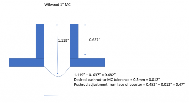
I was actually referring to a cylindrical spacer I made to lengthen the push rod. I removed that and didn't put it back. Your advice reminds me, though, that I didn't take my measurements with the flange/spacer installed between the booster and the MC, so everything is off by about 0.5" (thickness of the flange).
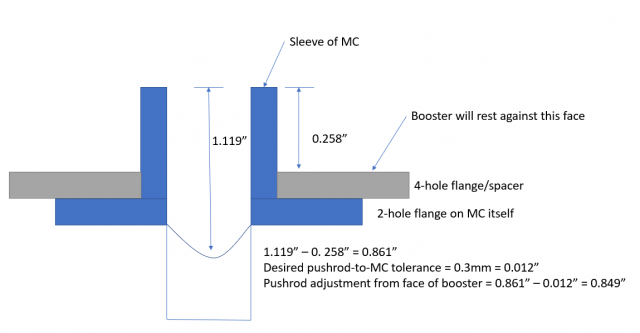
Here are the measurements and adjustment I made to the push-rod last night., but again I forgot to take into account the aluminum 4-hole flange/spacer between the booster and MC. This would add approximately +0.5" to the push-rod adjustment.

I took a measurement of the 4-hole flange/spacer and it should change my adjustment by:
Can you confirm my approach? I'm not sure how you went from 0.39" measurement to a 0.53" adjustment.
Also, thank you for the caliper bleeding tips. My bleed screws are not at the top of the caliper at all, so I will try the bench bleed technique you recommended after correctly adjusting the push-rod.
EDIT: @Miles Disregard my comment on how you got from 0.39" to 0.53". I didn't catch that it was illustrating the adjustment to a 240z stock push-rod position to accommodate a 280zx MC. Thanks.
-
This may end up being a long post because I want to highlight all of the things I've tried to get the brake pedal to not depress all the way to the floor.
1. I believe the brake booster is a 280zx booster. I had to widen the holes in the fire wall to get it to fit. I purchased the booster from O'Reilys.
2. I did the maxima caliper swap on the rear.
3. All brake lines to calipers are steel braided.
4. I removed the stock proportioning valve insides and converted it to a pass through splitter.
5. I first tried a 7/8" master cylinder and bleed the brake using several methods includ8.ing a pressure bleeder, traditional bleeding, and even an electric pump.
6. I thought that maybe the booster push rod wasn't quite long enough so I put a spacer in the end of the master cylinder. The brakes then worked well enough to stop the car, but only at the last 0.5" of travel.
7. I then removed the spacer and adjusted the push rod to almost touch the master cylinder plunger. The brake pedal still went to the floor with no stopping power.
8. I then removed the booster and checked that the reaction disc was still on the push rod. It was. I epoxied it to the push rod just in case. I reassembled the booster. I set the push rod clearance to 0.3mm.
9. I bench bled a 1" Wilwood master cylinder until there were no bubbles. I removed the check valve from the rear brake outlet.
9. I installed the 1" Wilwood master cylinder.
10. I installed a Willwood proportioning valve/switch in place of the stock brake switch/valve.
11. I bleed the brakes using the pressure/pump bleeder. It's basically a round-up sprayer with a cap you place on each reservoir and pump it up to 15 psi or so. I started at the furthest away wheel, then the rear left, the front right, the front left, and finally the MC itself. No bubbles come out of the calipers unless I loosen the bleeder a lot, at which point I think it's sucking in air from around the bleeder screw so several small bubbles show up at that point. After bleeding the pedal still depressed to the floor.
12. I then got a helper to pump the brakes and I bled each caliper the traditional way. The pedal STILL went to the floor.
I'm out of ideas and at a loss. Especially after dripping brake fluid on the fresh paint and melting it.
Does anyone have any ideas that might help out? Could the calipers themselves be screwed up? Is there a second bleeder on the calipers that I need to bleed?
-
3 hours ago, NewZed said:
The 84-89 300ZX used a 71C also, along with the BW 5 speed.
Great. I didn't know that. I had heard that the 71C is a little stronger than the T5 BW so I've been looking for the 71C.
Do you know if the SR20 5 speed has the same gear box as the KA24 5 speed?
-
Looking for an '89 - 98' 240sx KA24DE (FS5W71C) 5 speed transmission.
-
7 hours ago, bradyzq said:
It sounds to me as if you expect the dyno to be hard on the driveline. It shouldn't be. There will be no shock loading or wind-up. The only part that might complain, because it's stuck in the middle so to speak, is the clutch.
If there are currently no hints of imminent driveline failure, I agree with NewZed on treating the ujoints to fresh grease. Also applies to the transmission and diff. I like Redline MT90 for the transmission, and Redline 75W90 GL5 oil for the diff.
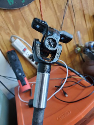
I added fresh Redline MT90 and diff oil to the transmission and diff, but the ujoints oddly do not have a place to add grease or take out a plug. The part number on them is Koyo KC1819D. Is that the stock part? Here is a video of one of them:
-
On 6/25/2020 at 9:22 AM, NewZed said:
The u-joints can all be lubed. They might not have a Zerk fitting but they should have the hole with a slotted plug in it. Take the plug out, put a Zerk in, fill them up, and put the plug back in. Inspect the seals and seams closely for rust or looseness. If you do find a bad one, just replace the one. I found that the new aftermarket joints were looser than old Nissan joints.
I took a look and didn't see the plugs in the current u-joints. Not sure if they had different ones that did have the plug. These are labeled Koyo.
-
41 minutes ago, jhm said:
Unfortunately, I don't think there's a single definitive way to answer that. It all depends on a variety of factors....how you plan to use the car, what transmission you're using, what tire/wheel combo you're running, condition of your current internal hardware, etc. Auto trans are usually kinder to the drivetrain than manual trans. Lighter cars can have less drivetrain failures than heavier cars. Big tires can impart more abuse on drivetrain components than small tires. (IINM, open diffs can have more failures than LSDs; but that may not really be a good apples-to-apples comparison.)
I've broken my diff carrier with a very mild SBC motor, but was running tight auto-x courses on sticky slicks. Haven't had to replace my stub axles yet, but have seen many fail with bigg'ish hp/torque and multiple hard launches on big tires. This seems to be the common theme with failed stubs.
Is this primarily a race car or street car? I'd say let that factor guide your decisions, and upgrade/replace components as it becomes necessary. 300 HP (with similar torque numbers) can move your car along quite well for most applications. Beefier components are readily available; it just takes money. The R200 is a popular upgrade to the R180, and stronger stub axles are available from several vendors.
Good luck with it.
That all makes sense to me. It's primarily a street car and weekend cruiser, so I don't plan to make huge HP and torque. The tires are close to stock as well.
Thanks! Maybe I'll report back with some dyno numbers in a week or two.
-
10 hours ago, NewZed said:
The Nissan u-joints are of very high quality. $80 each, with precision clips to ensure an exact fit. If they're not dried up or rusty, why replace them with $20 u-joints?
The R180 will probably blow before the u-joints.
4 minutes ago, jhm said:I agree with NewZed...if your stock driveshaft u-joints are in good shape, just leave them alone. If they eventually do need to be replaced, I'd consider Spicer u-joints. Have worked well for many folks here.
Similarly, the stock half-shafts are quite stout; and can handle quite a lot of abuse.
There are other components that will fail first....diff carrier gears, outer stub axles, etc.
Great. Thanks for the feedback -- I appreciate it.
Do you have any data points on at what torque the outer stub axles and/or diff carrier gears start to fail? There are of course a lot of other variables like the condition of the splines and gears, but I'm just curious so I can have a "do not exceed" number for the dyno tuner.
-
Hey guys,
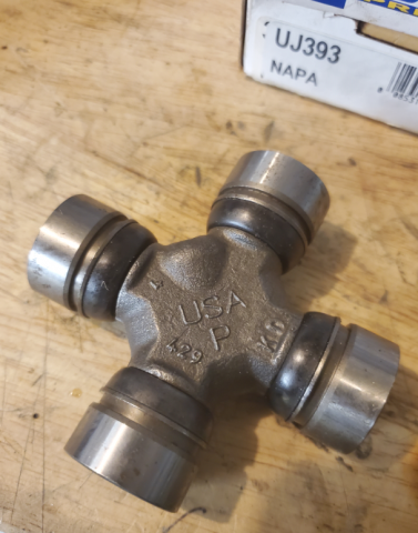
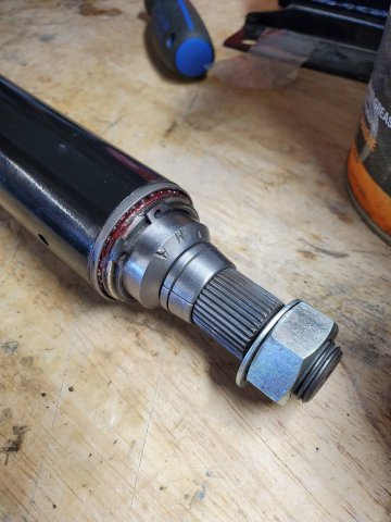
So I'm getting ready for a trip to the dyno after my fresh rebuild and Megasquirt MS3X install. The engine is all fresh and I've barely driven it. One thing I didn't do is replace the original halfshaft and driveshaft u-joints. I have some new NAPA UJ393s for the halfshafts and NAPA P391s for the driveshaft that I plan to put in before the dyno run.
My question is, would it be better to order the heavy duty u-joints from MSA or will the NAPA u-joints be fine? Differential is the original R180. Planning to make around 300HP this first round.
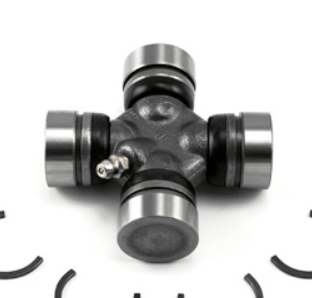
Link to heavy duty joints. It looks like they have more meet around the trunion compared to the NAPA ones.
https://www.thezstore.com/page/TZS/PROD/22-3004
Heavy duty:
NAPA:
-
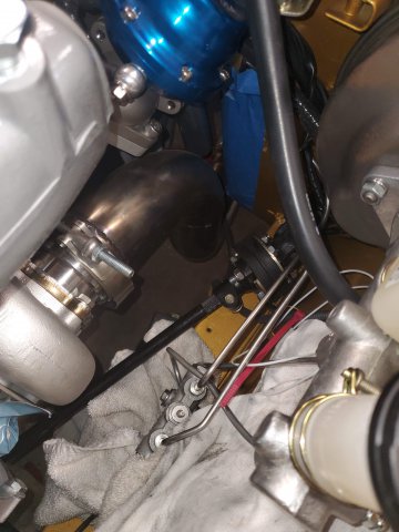
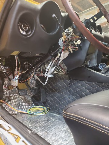
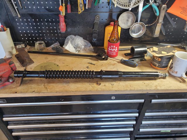
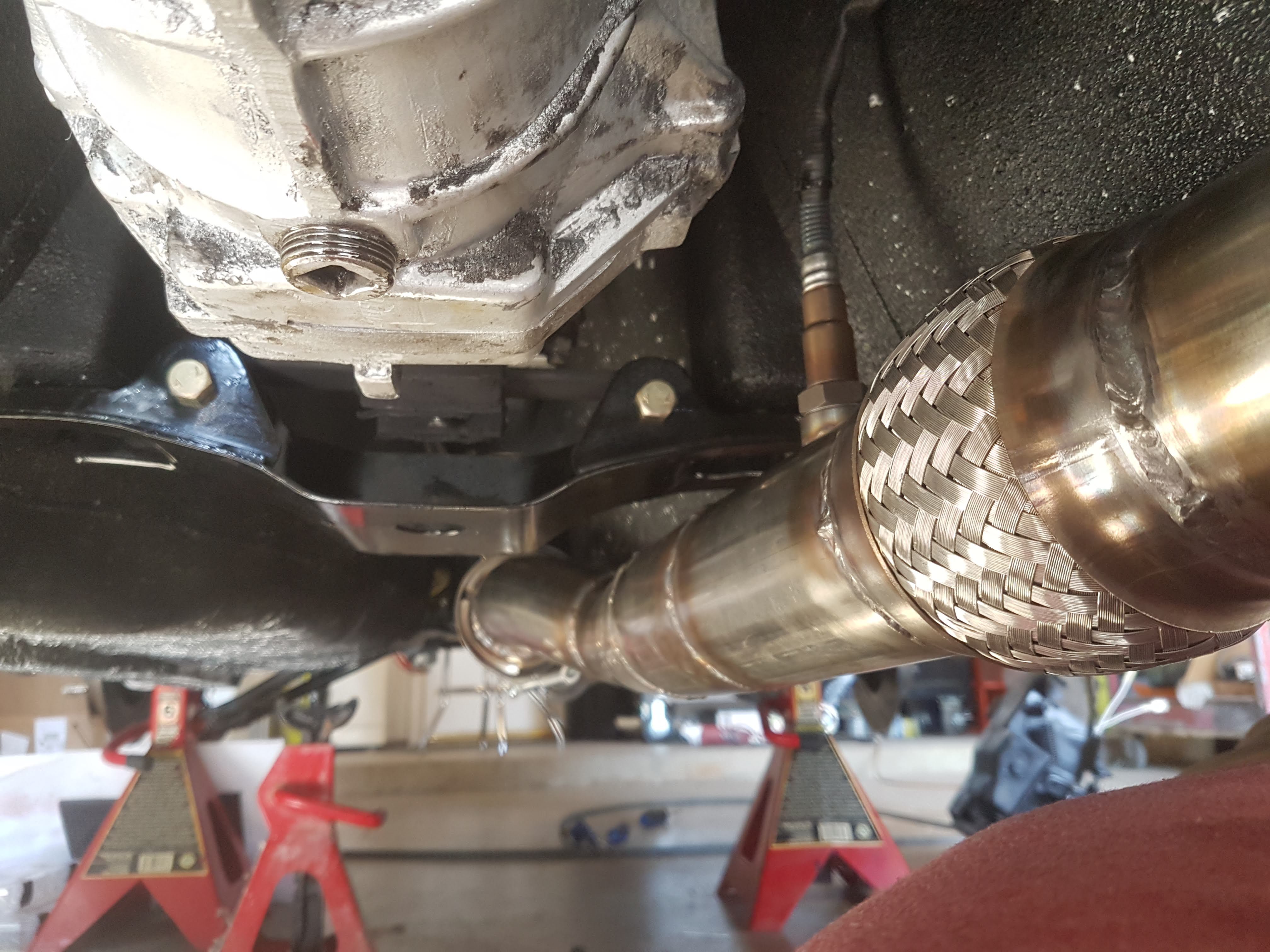
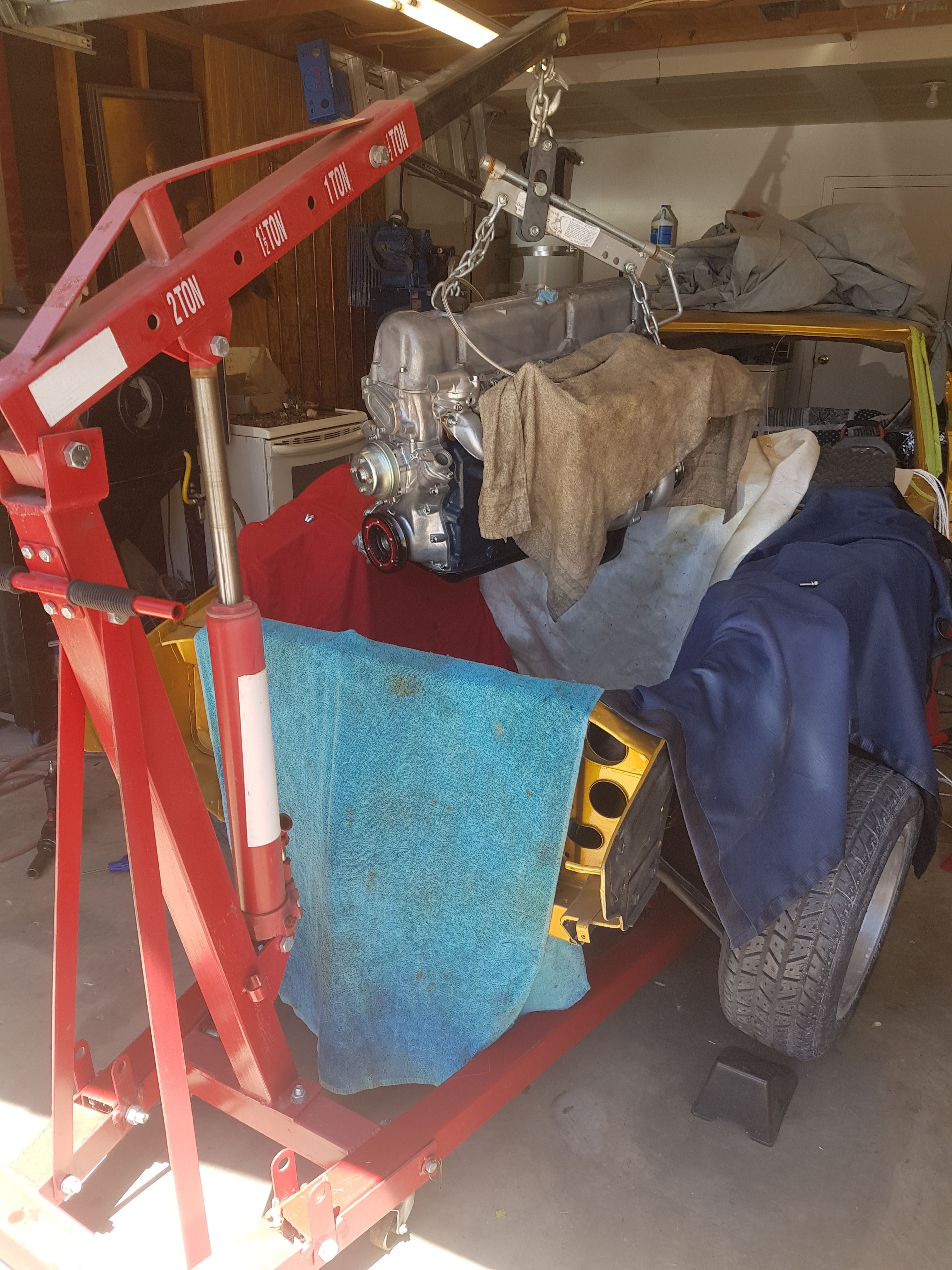
Installed the steering column and steering coupler. The steering coupler shaft interferes with my turbo oil drain, so I ordered 90" 3/4" barb for the drain that should solve the problem. Hoping for a maiden voyage this weekend!
-
 1
1
-
-
On 12/23/2019 at 6:00 PM, Fauxre said:
3. and Christmas Village 2019 ( in 3D ) is finished. It's so big we had to use two rooms this year.
Digging the village ski hill!
Nice composite work, too. What are you repairing on the bottom of those three scoops? Looks like some Everglass in there. It kind of looks like the composite cracked off further in and that's what you're replacing?
-
On 2/3/2020 at 3:29 PM, Fauxre said:
The body kit is a Velo Rossa. It's styled after the early 60's Ferrari 250 GTO. John Washington of ZTrix.com makes it.
Tires are 245/45/17's up front and 275/40/17's in the rear. Had to do some minor surgery to those fenders to get them under. My build is here, Velo Rossa Build, if you're interested.
Very cool. I'll check that out.
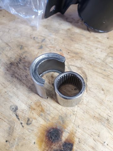
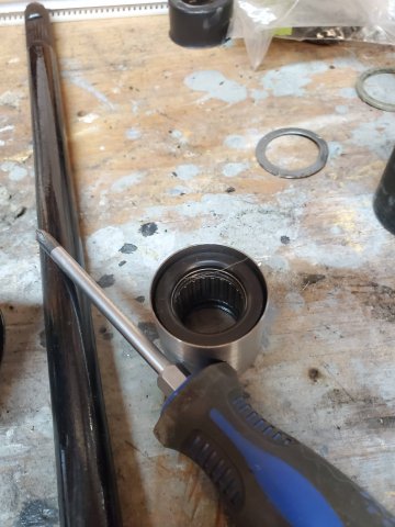
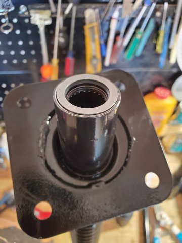
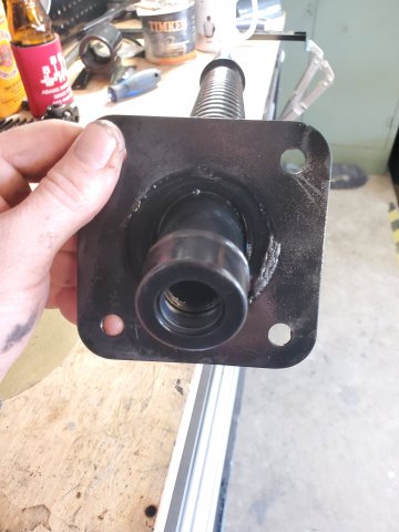
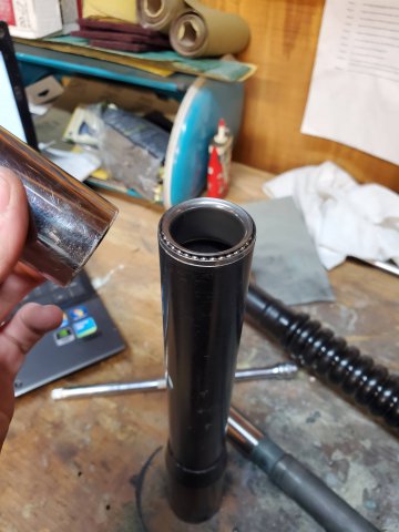
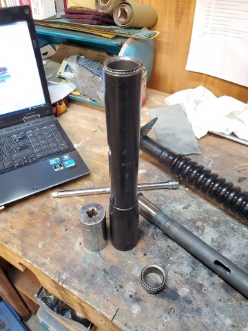
I finally assembled the steering column. I had to machine a new end bearing sleeve for the needle bearing in the end of the steering column. Everything went back together great and the column feels sweet. No freeplay or binding.
Shooting for a maiden voyage of the car this weekend. 4+ years coming!
The old broken sleeve and needle bearing.
The sleeve I machined, the rubber isolator, and the needle bearing.
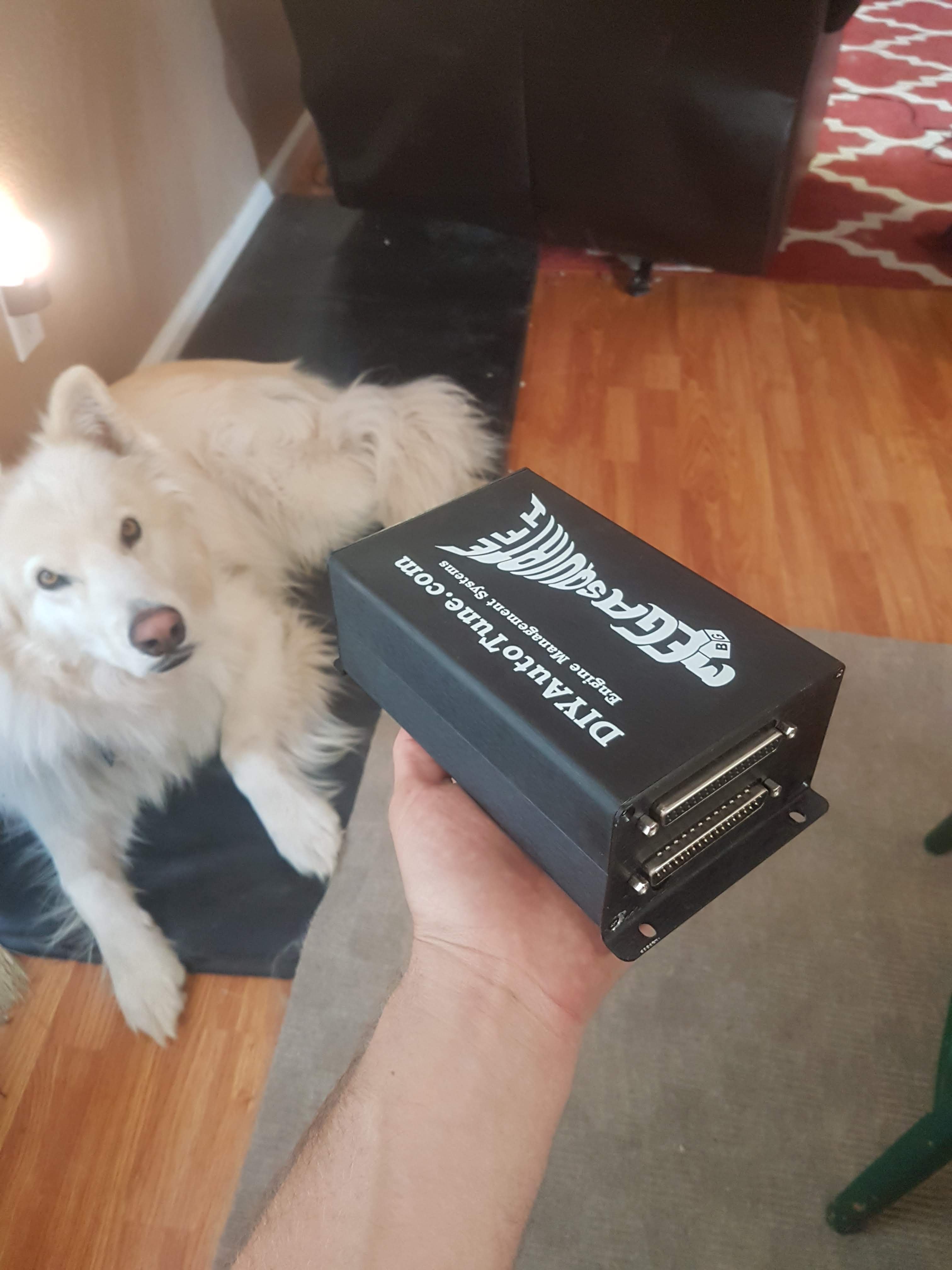
Bonus doggo.
-
On 1/29/2020 at 9:34 PM, Fauxre said:
Thanks jKelly for those links. Looks like you've covered everything.
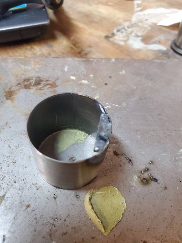
I don't need the lower portion of the steering column for my conversion. I didn't find a needle bearing at the bottom, although I did find a rubber seal that is not meant to be removed, just the same bearing as the top. I was able to remove the bottom bearing without any damage by using a 3/4 inch pvc coupler and a length of copper pipe. I'll try to do the same with the top after I have every thing lined up and tacked in their final positions. I should be able to cobble together one good bearing from the pieces of both.
BTW, I like your wheel choice. I went with a similar look, Roto RB's ,17"x9.5 rear and 17x9 front... hence the need for power steering.

Excellent. Glad you got the bearing out without damage. If you want some new 1/8" balls shoot me a PM and I'll send them your way free of charge. I bought 100 of them after all.
What body kit is that? It looks far out. Gotta make room for those wheels. I'm on Konig Rewind 15"x 7s. What's your tire size?
-
On 1/23/2020 at 8:39 PM, Fauxre said:
Wow!!! Very impressive build. Clearly a labor of love.
I'm currently in the 12th year of my 260Z to Velo Rossa project. Been away from it for a few years as life keeps getting in the way. But I'm finally back at it and I'm currently in the middle of converting to an electric power steering unit from a Saturn Vue. My steering column bearings are in bad shape and I haven't seen any replacements sold anywhere. I was hoping you could expand on exactly how you refreshed yours. How did you remove them without damage? Where would I get more ball bearings? What size balls? Etc..
There's this forum post that kind of describes the process: https://www.zdriver.com/forums/240z-280zxt-s30-s130-tech-tips-275/steering-column-fix-15966/
Also this manual that has some decent diagrams that might help: http://pdf.textfiles.com/manuals/AUTOMOBILE/NISSAN/240z/1973/ST Steering.pdf
This post talks about the process in good detail, too. Try searching for "bearing" in this post: http://japanesenostalgiccar.com/forum/forum/garages/datsun-nissan-garage/4020-project-s30z-my-swiss-datsun-240z-1972/page40
Good luck!
-
Hey, thanks! I know how the delays go. I'm 4+ years in now, but almost there. That last 10% takes twice as long as the rest.
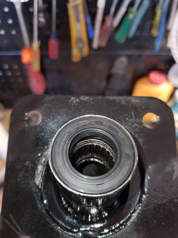
I can't recall how I got the bearings out, but I imagine I used a pipe of some sort to hammer them out. Maybe even a PVC pipe. I will go back through my pictures and see if I have some that show that. Also, I would not recommend removing the needle bearing in the end of the steering column. It's not meant to be removed and I did destroy part of it. It's a needle bearing surrounded by a rubber bushing and encased in a metal sleeve. I damaged the sleeve and need to machine a new one. I was able to find a replacement bearing, but not replacement rubber isolator and metal casing.
The other bearings, though, are 1/8". https://www.amazon.com/gp/product/B006PQLP9S/ref=ppx_yo_dt_b_search_asin_title?ie=UTF8&psc=1
-
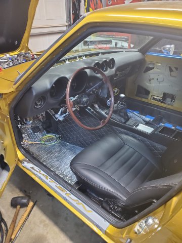
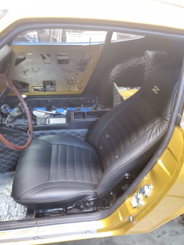
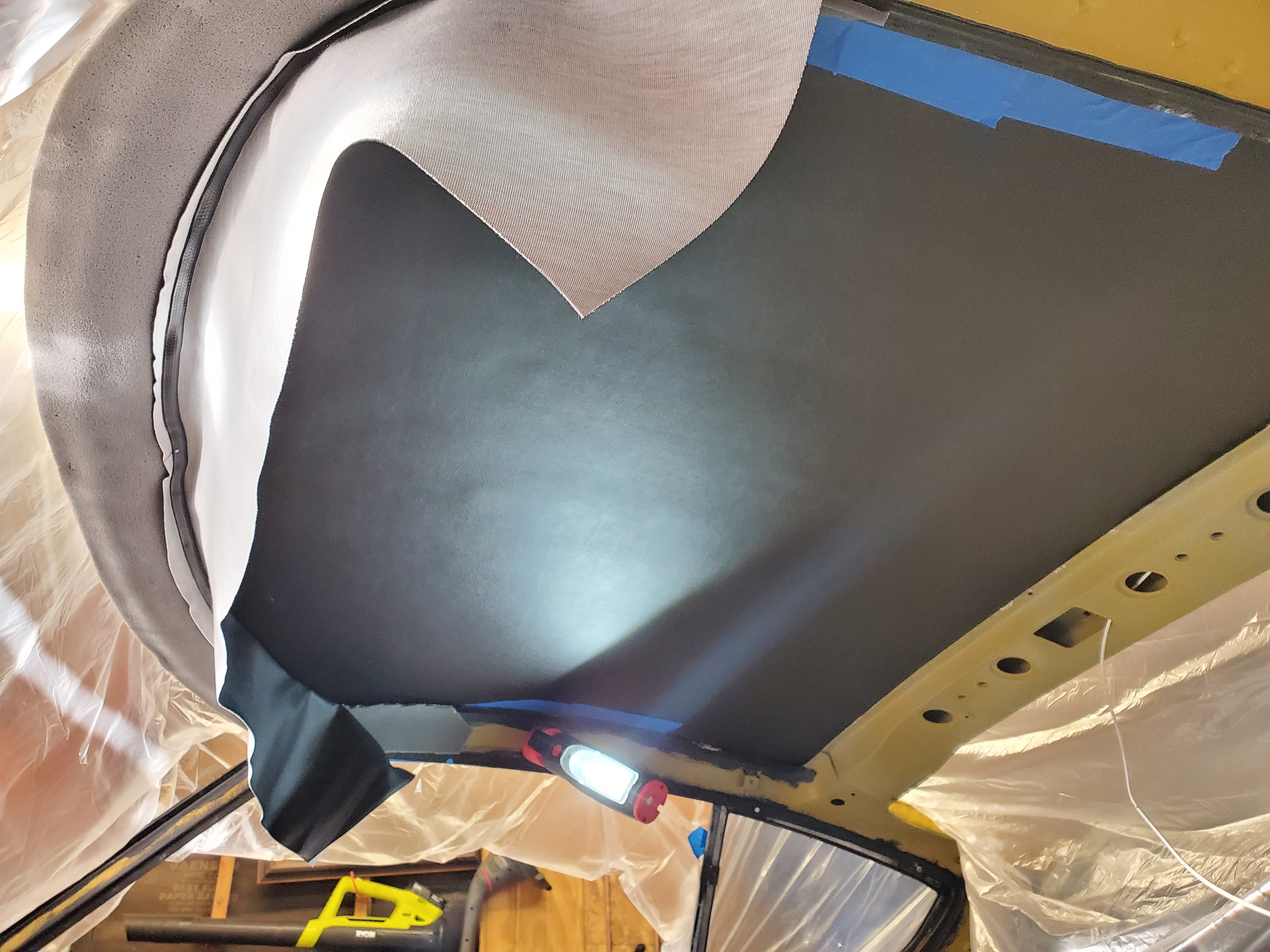
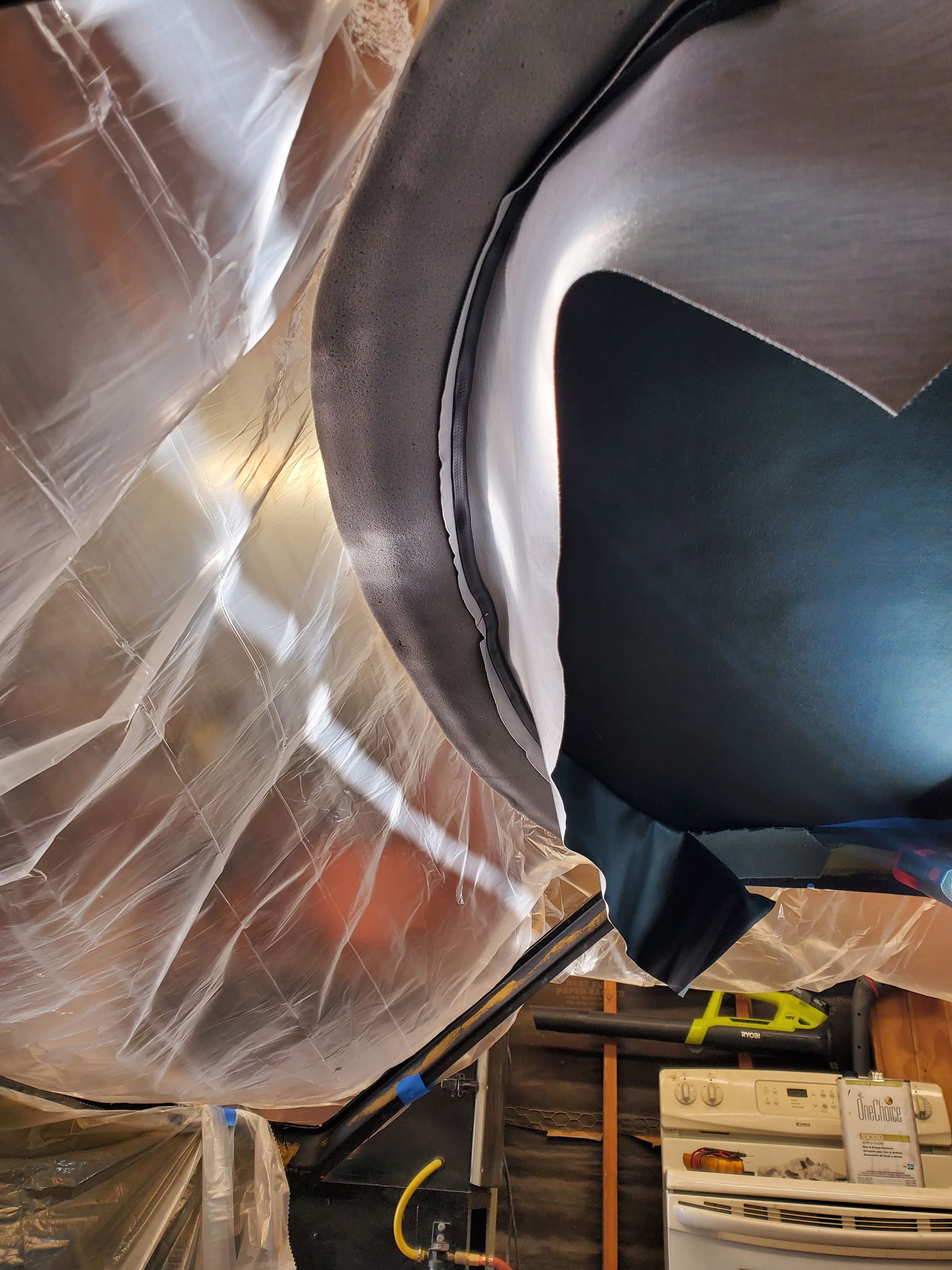
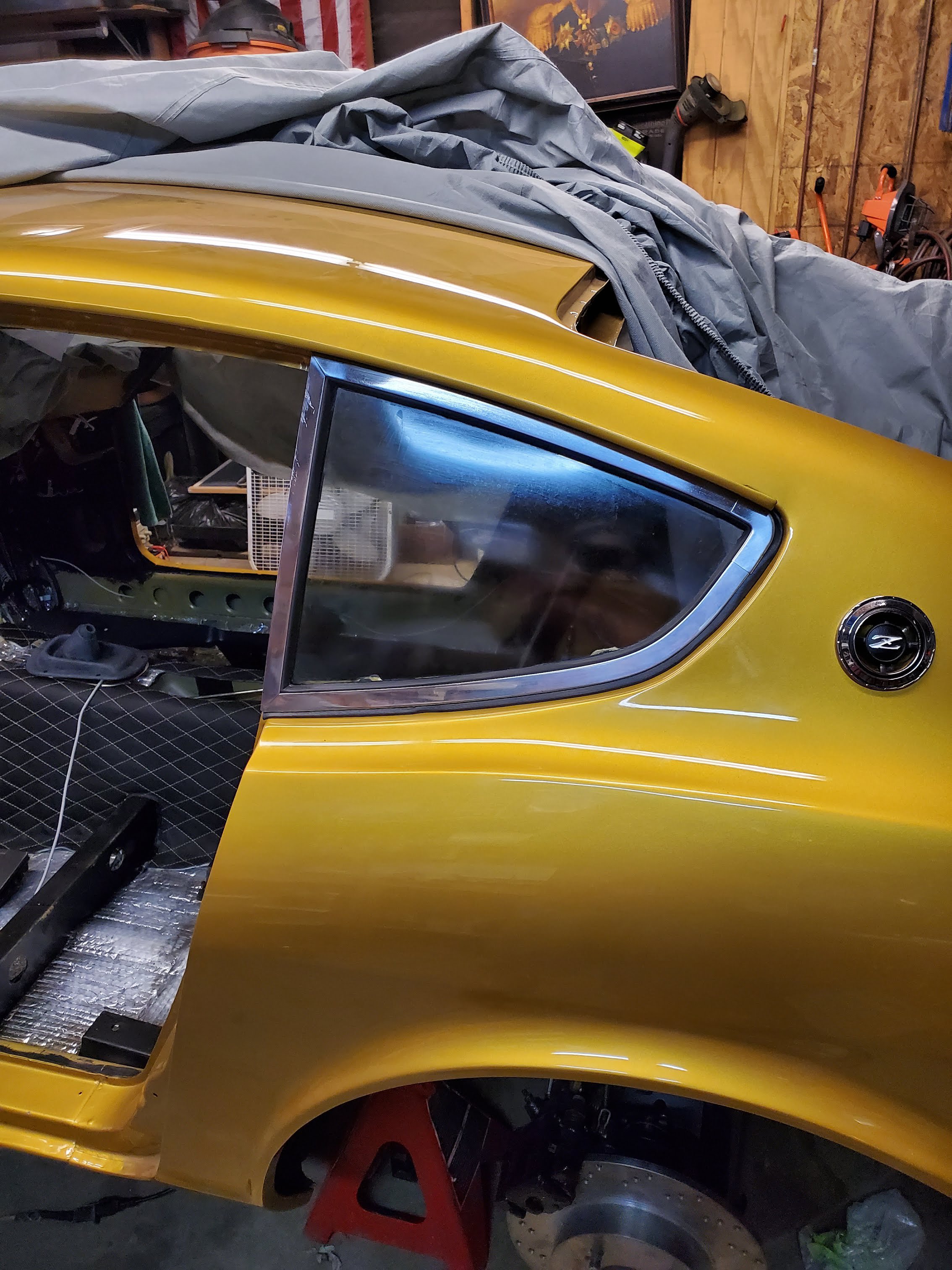
Recently I put in a new headliner. This wasn't as difficult as it seemed at first, but it certainly helps having two people there. I also started putting in new window header vinyl. This took a few tries to get it smooth. I'll upload final pics of this tonight or tomorrow.
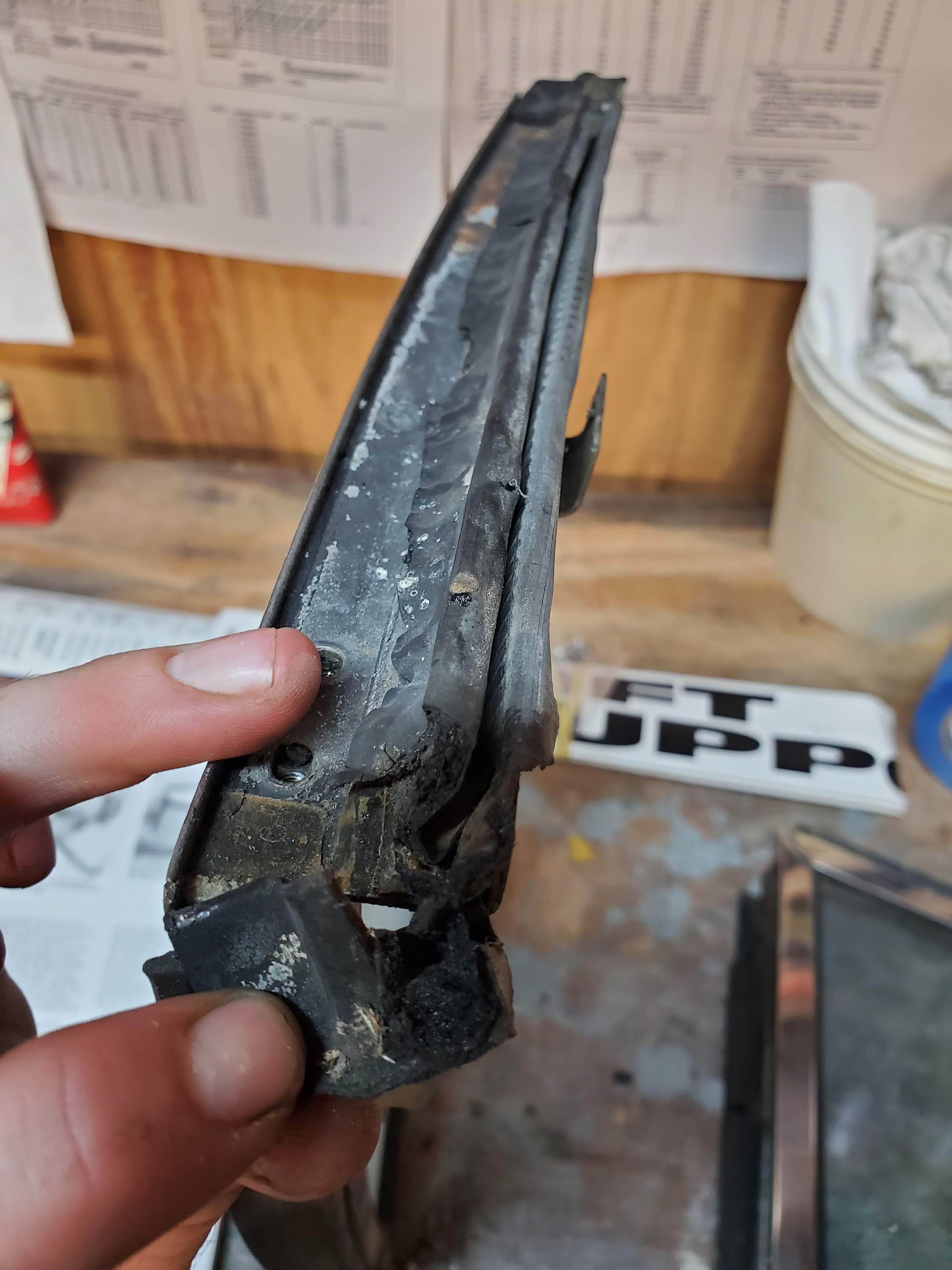
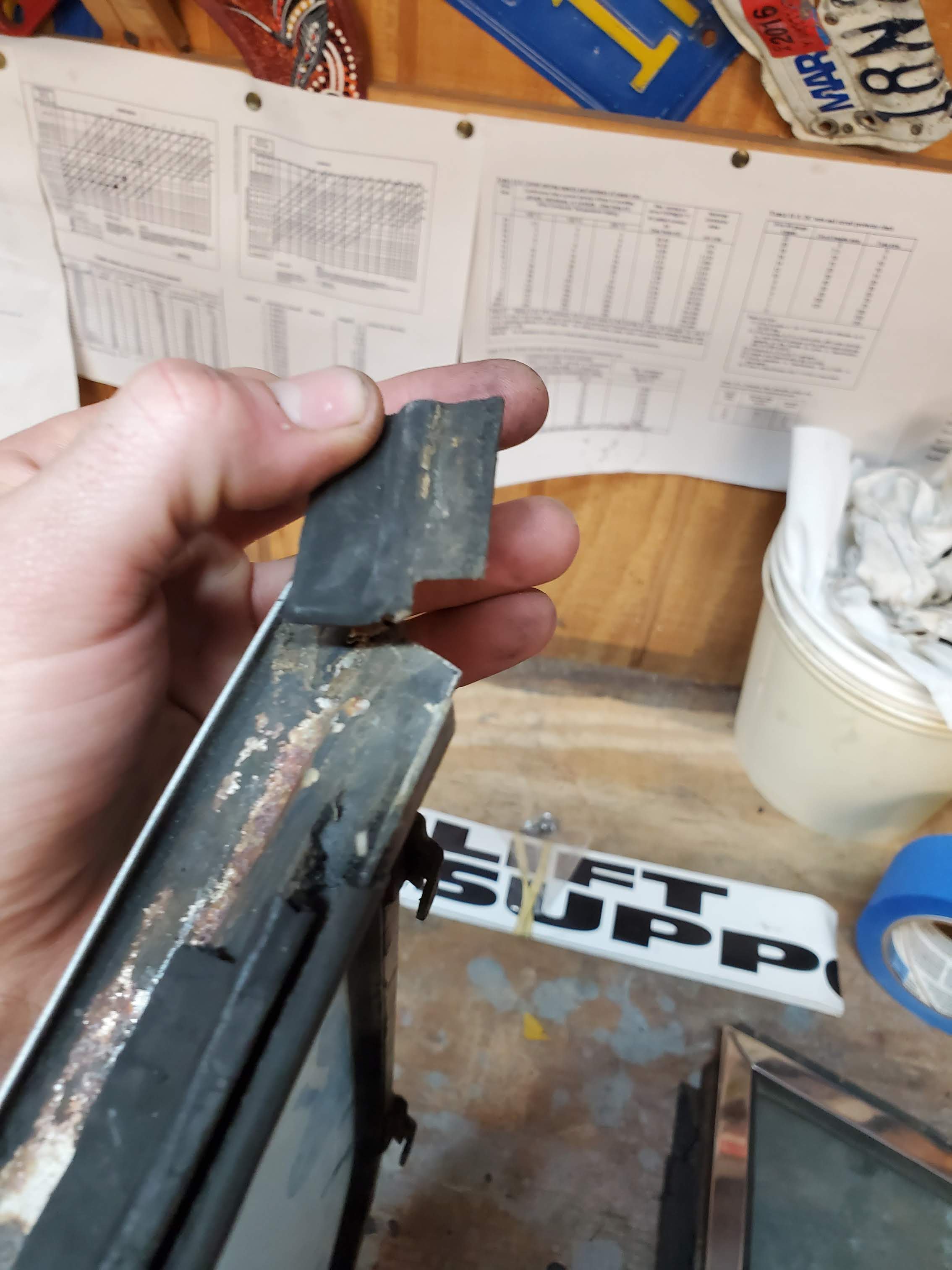
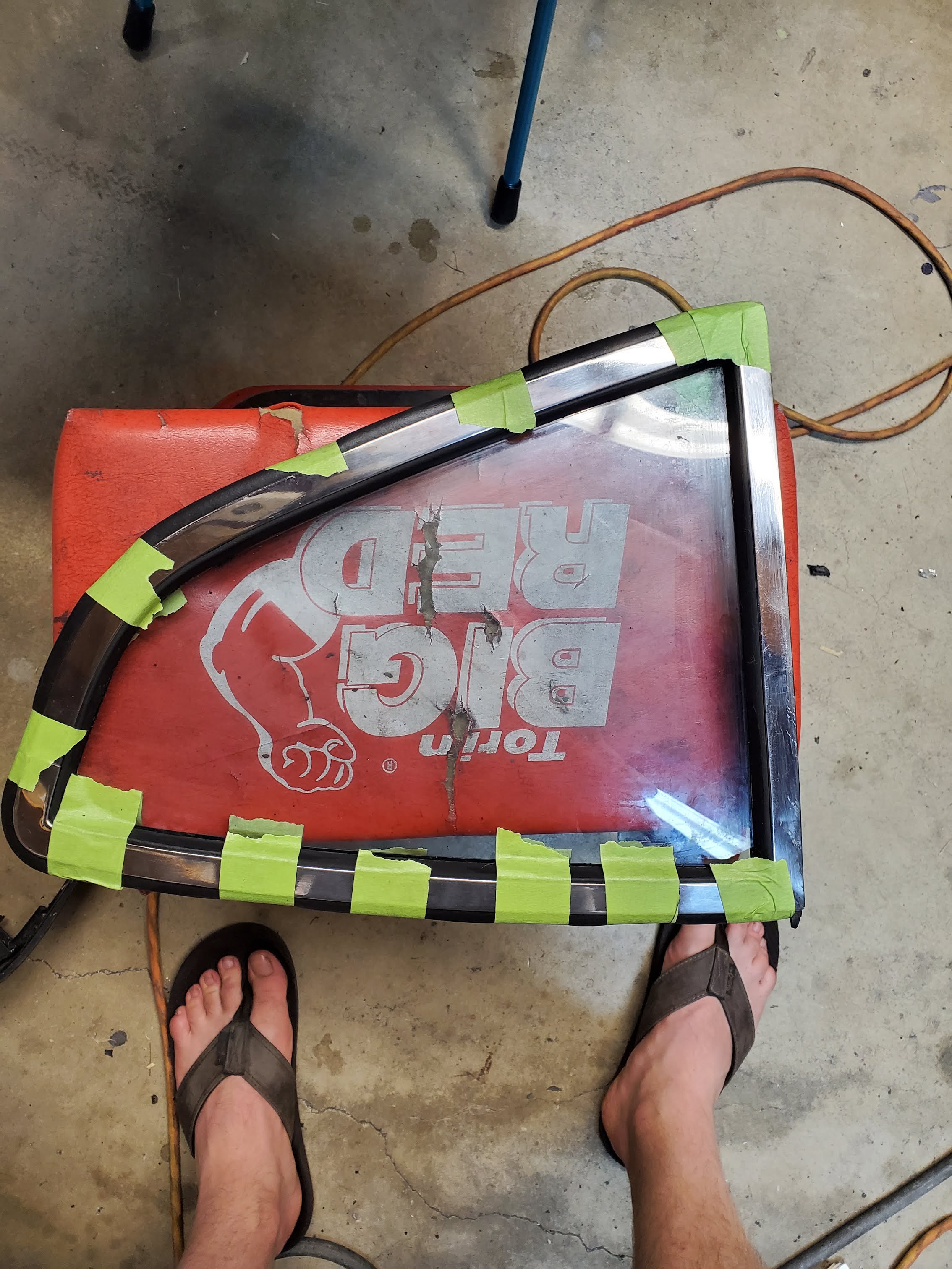
I also rebuilt the quarter windows with new inner and outer weatherstripping. These were pretty hard to get back into the car because the weatherstripping doesn't like to compress. I found using longer M4 screws helps to grab the screw hole threads and pull it in. This would have been easier with two people -- one person pushing on the window while another threads in the four screws.
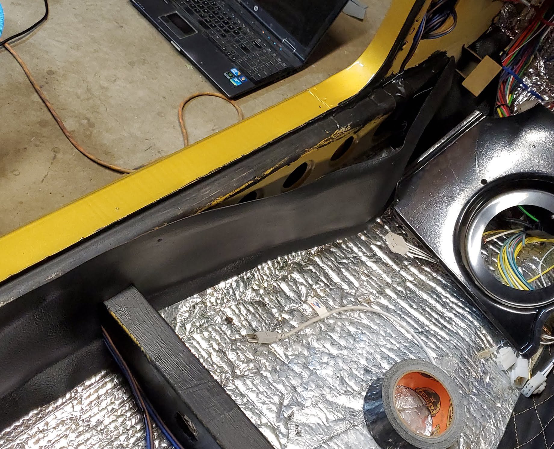
I also started laying down the interior vinyl (transmission tunnel, strut towers, inner-rockers, wheel-wells, etc.
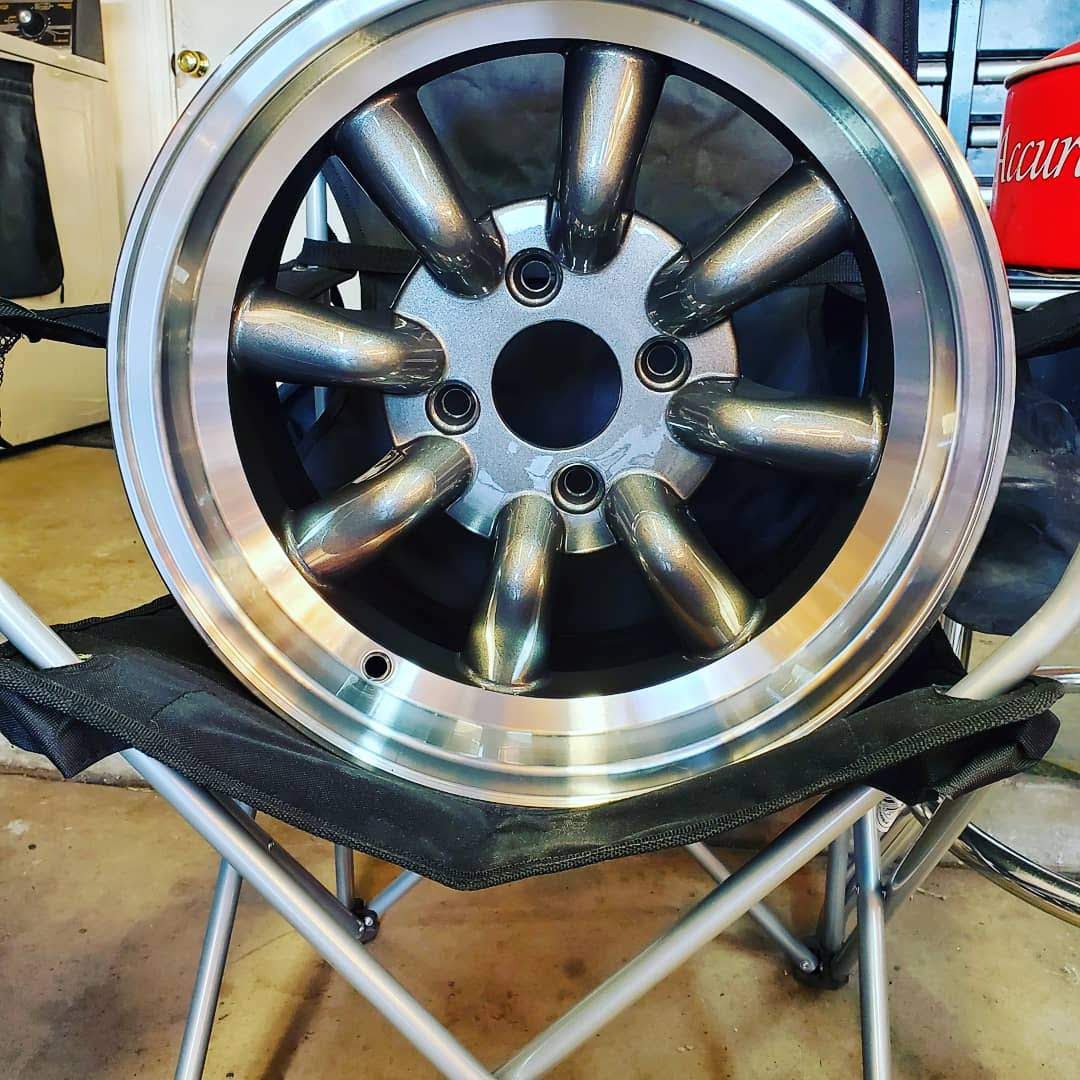
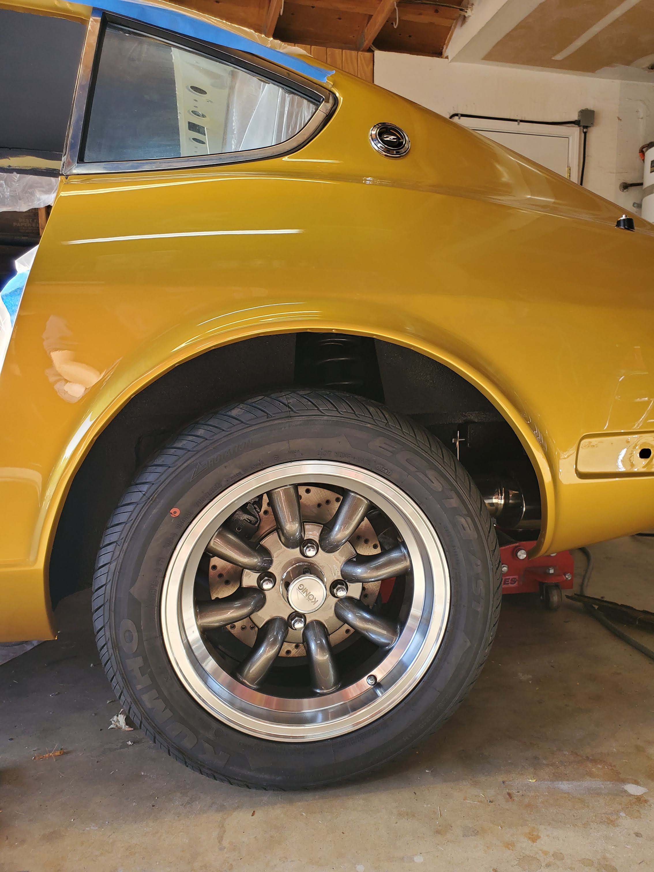
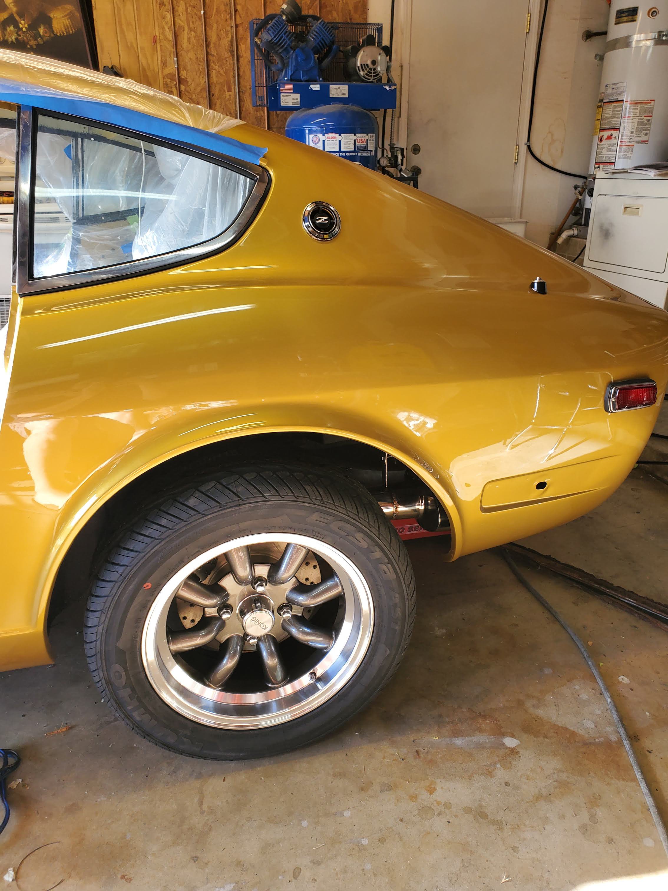
I went with 15" graphite Konig Rewinds for wheels. I put these on and over the the course of just 48 hours the car settled and the tire/fender gap looks great now!

-
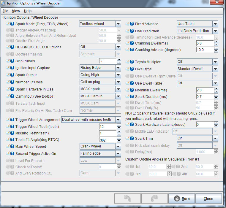
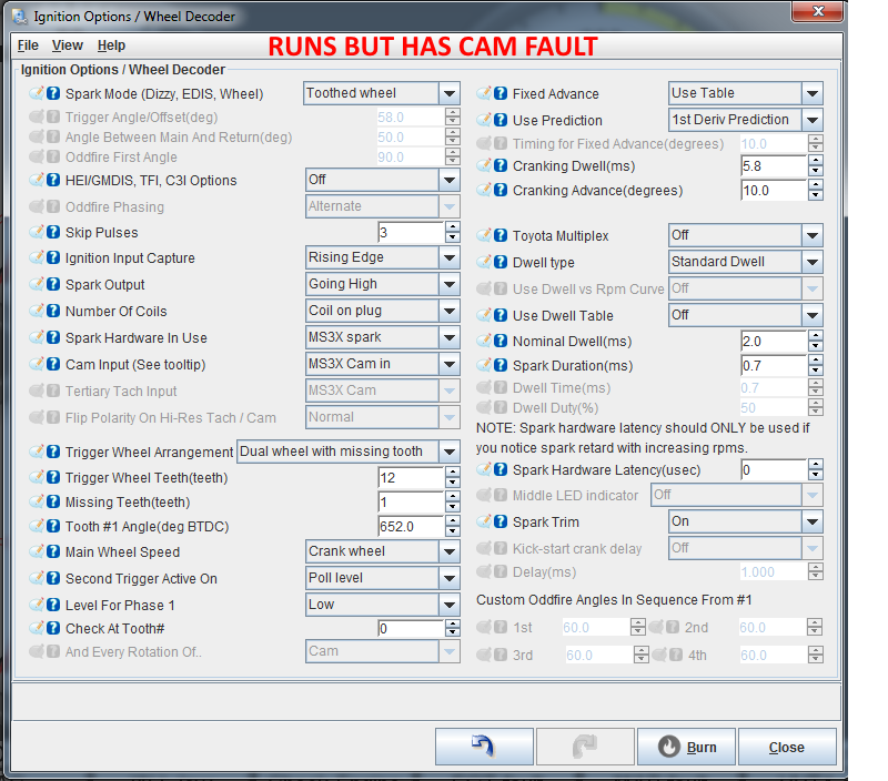
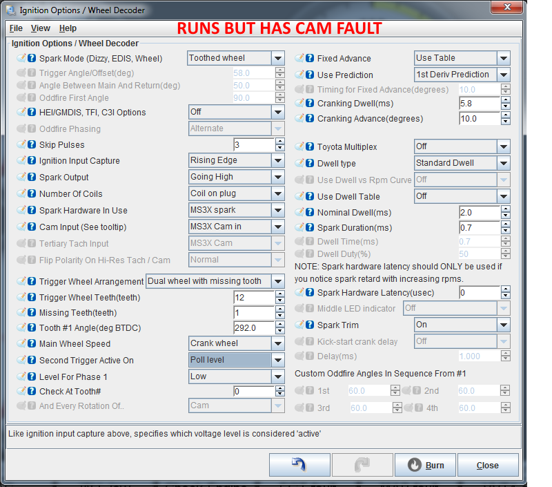
I'll follow up on this for archive/search purposes since it's been resolved. I did get the car to finally start using the following settings and in full sequential and COP mode with no CAM Fault and full sync. I'm not sure why it didn't start the first time I had this settings burned on the MS3. I did find my timing was off by 10º BTDC and it's possible the required fuel and VE table may have not been dialed in well enough.
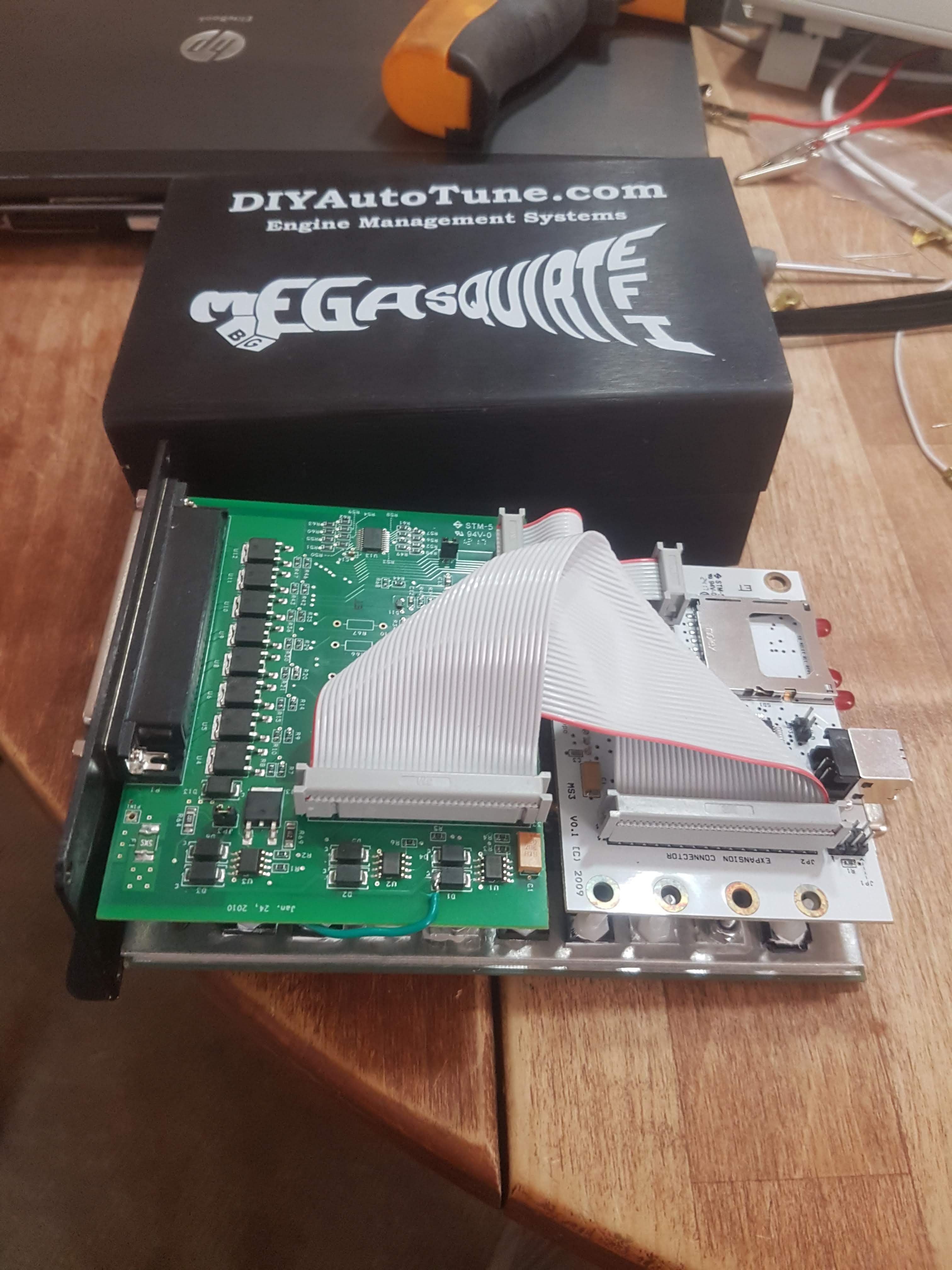
Thanks to Matt at DIYAutoTune for helping out.
-
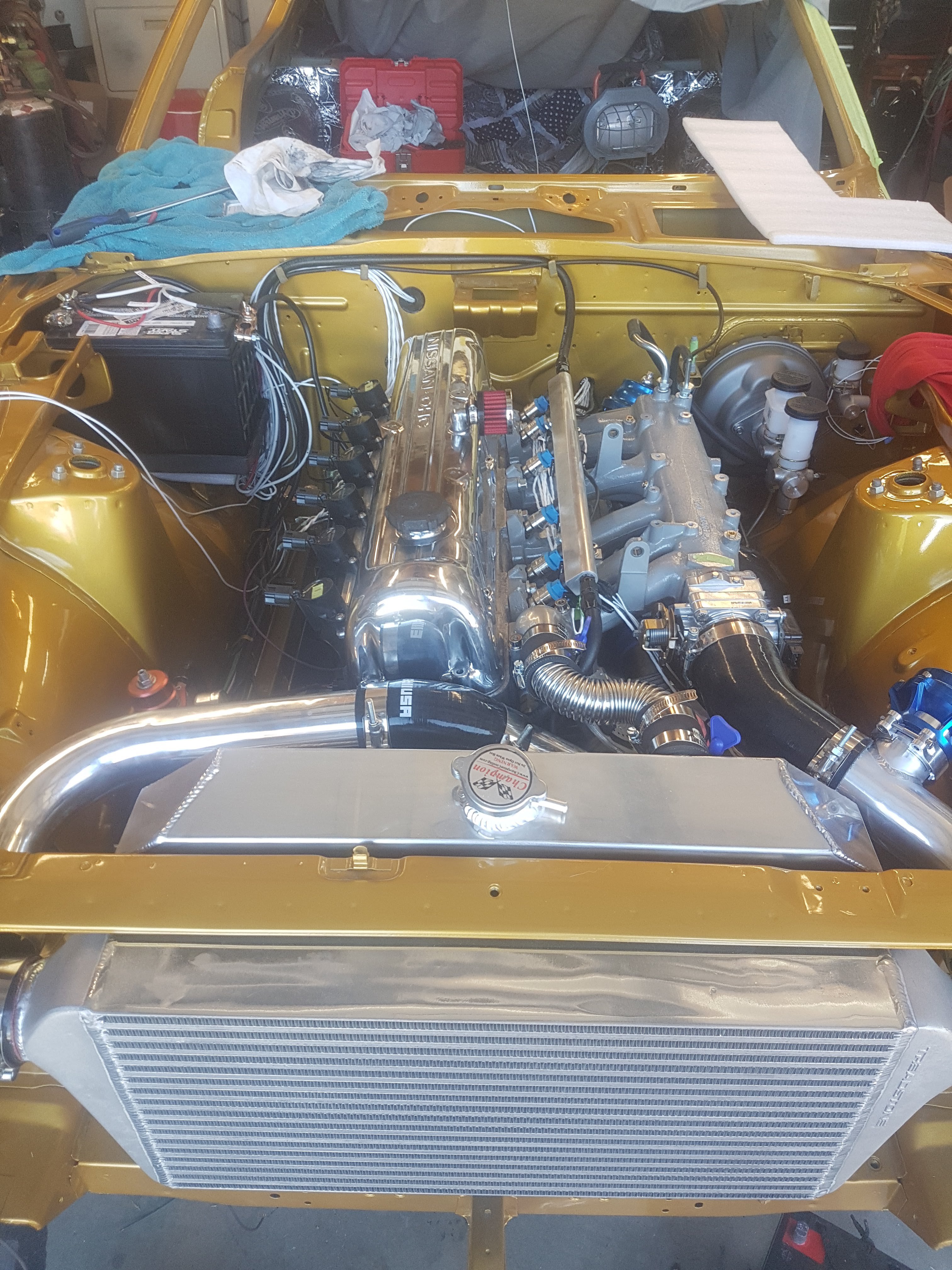
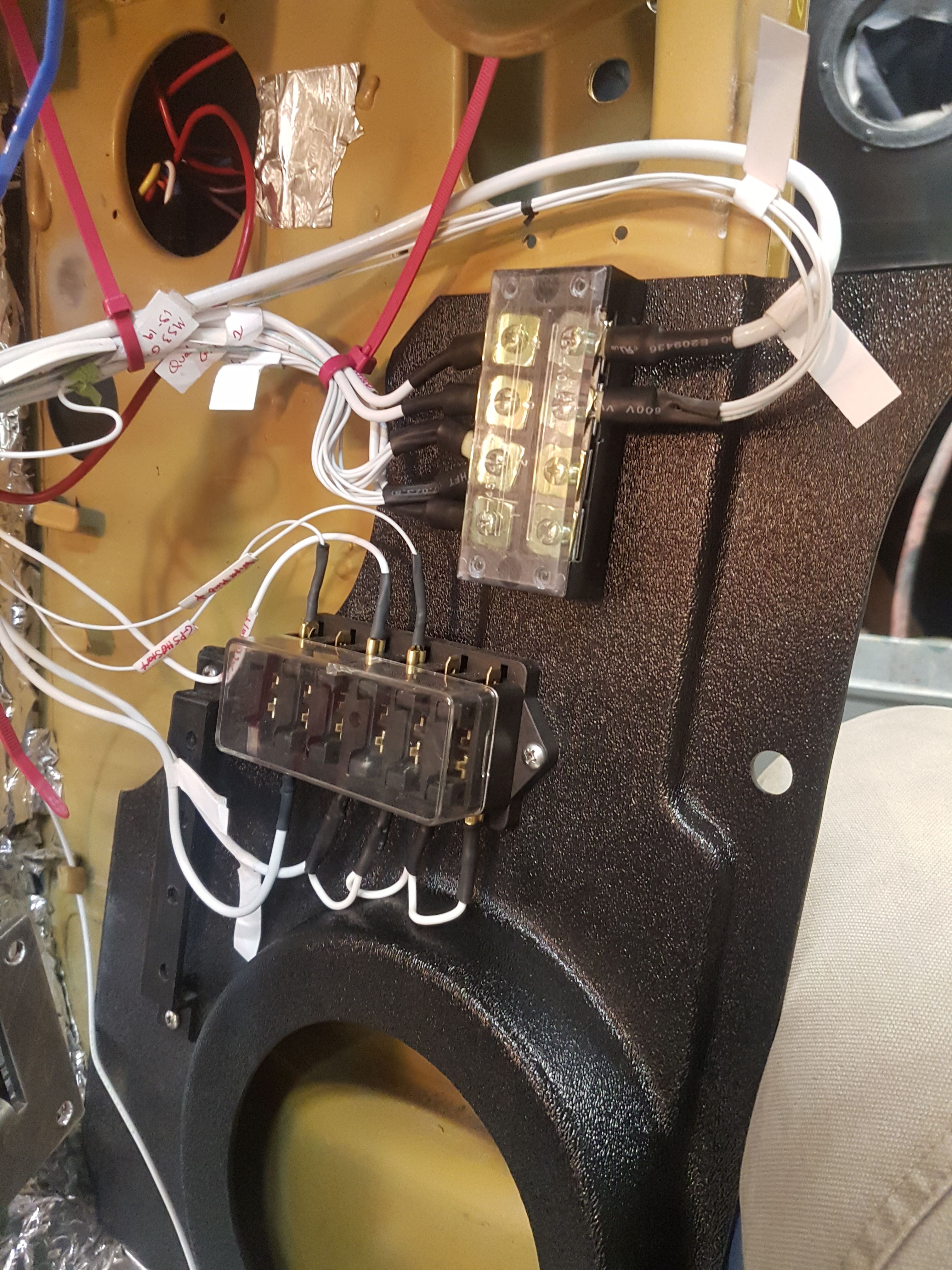
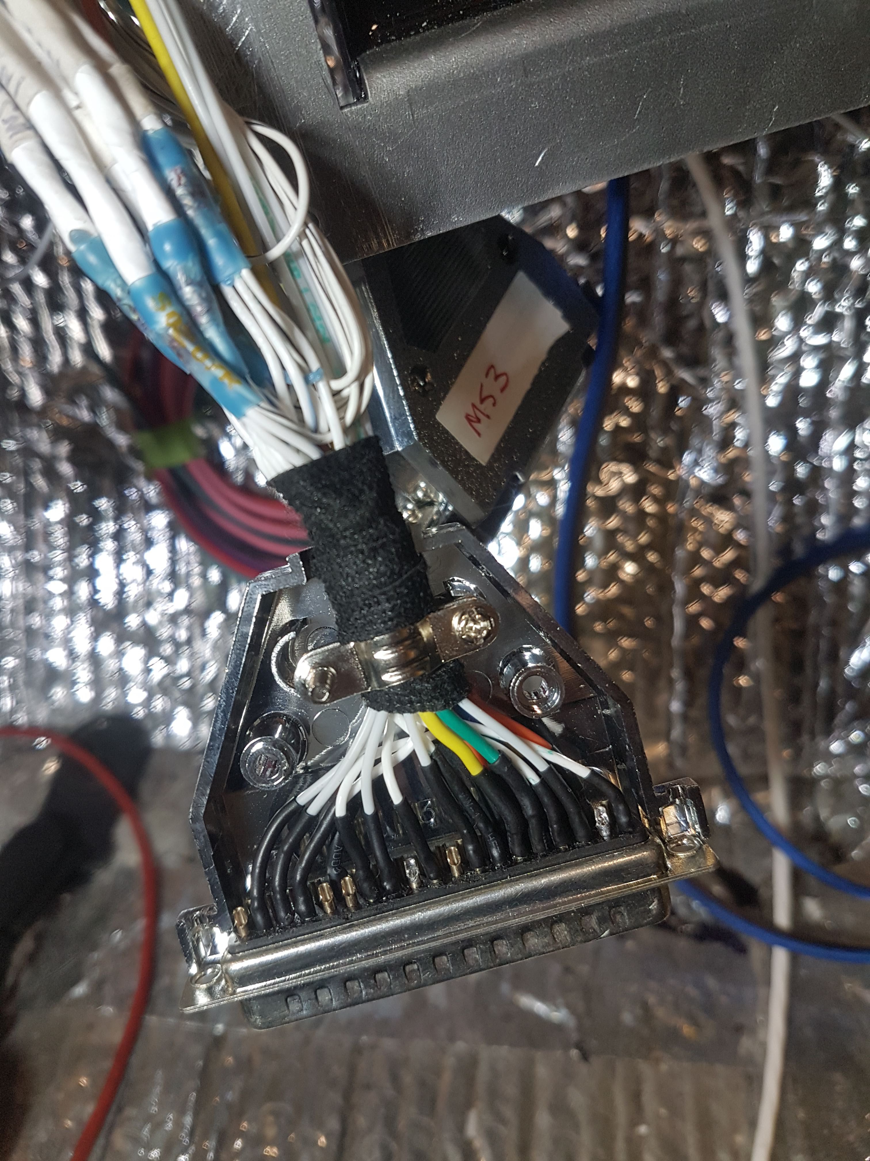
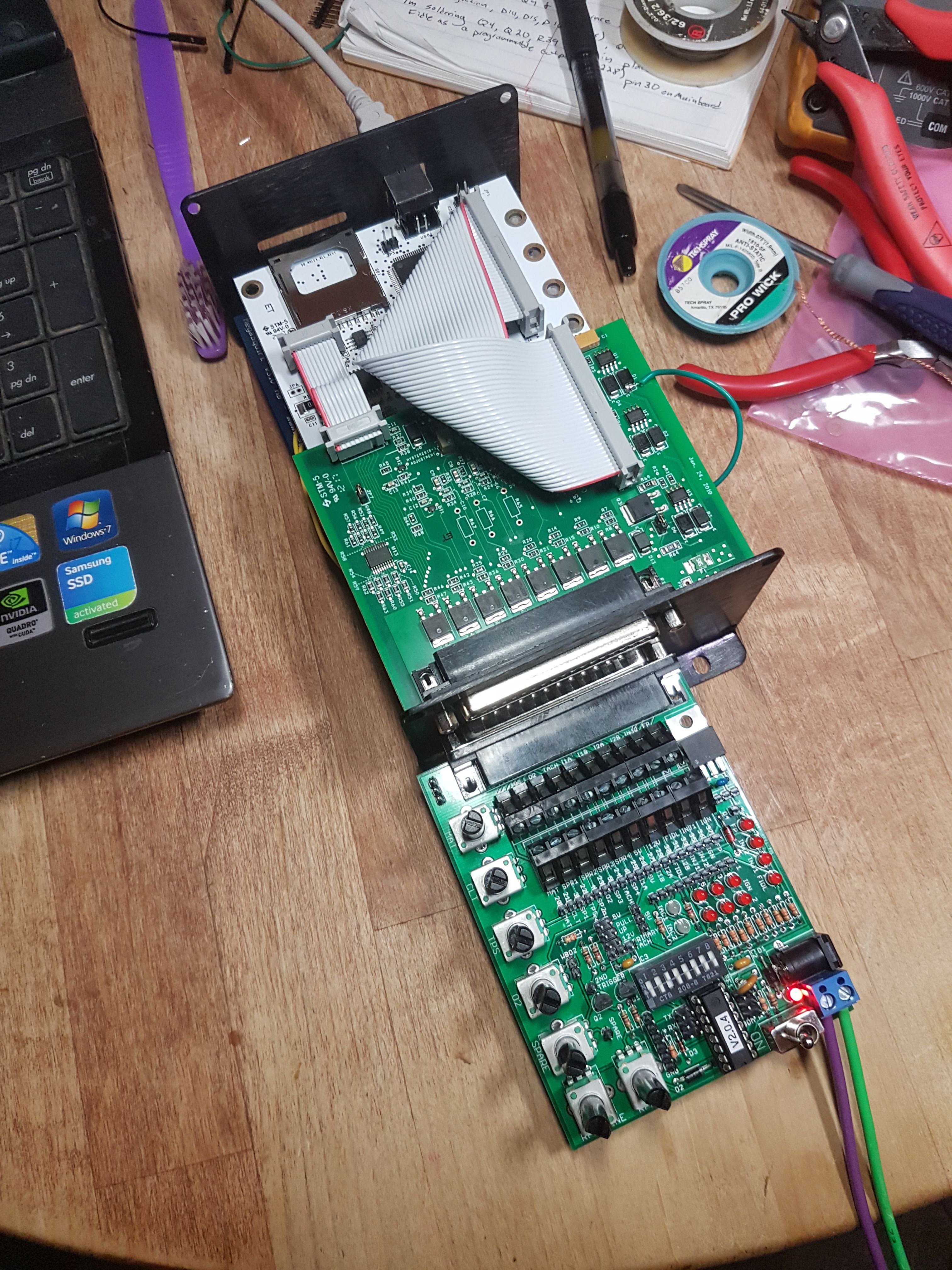
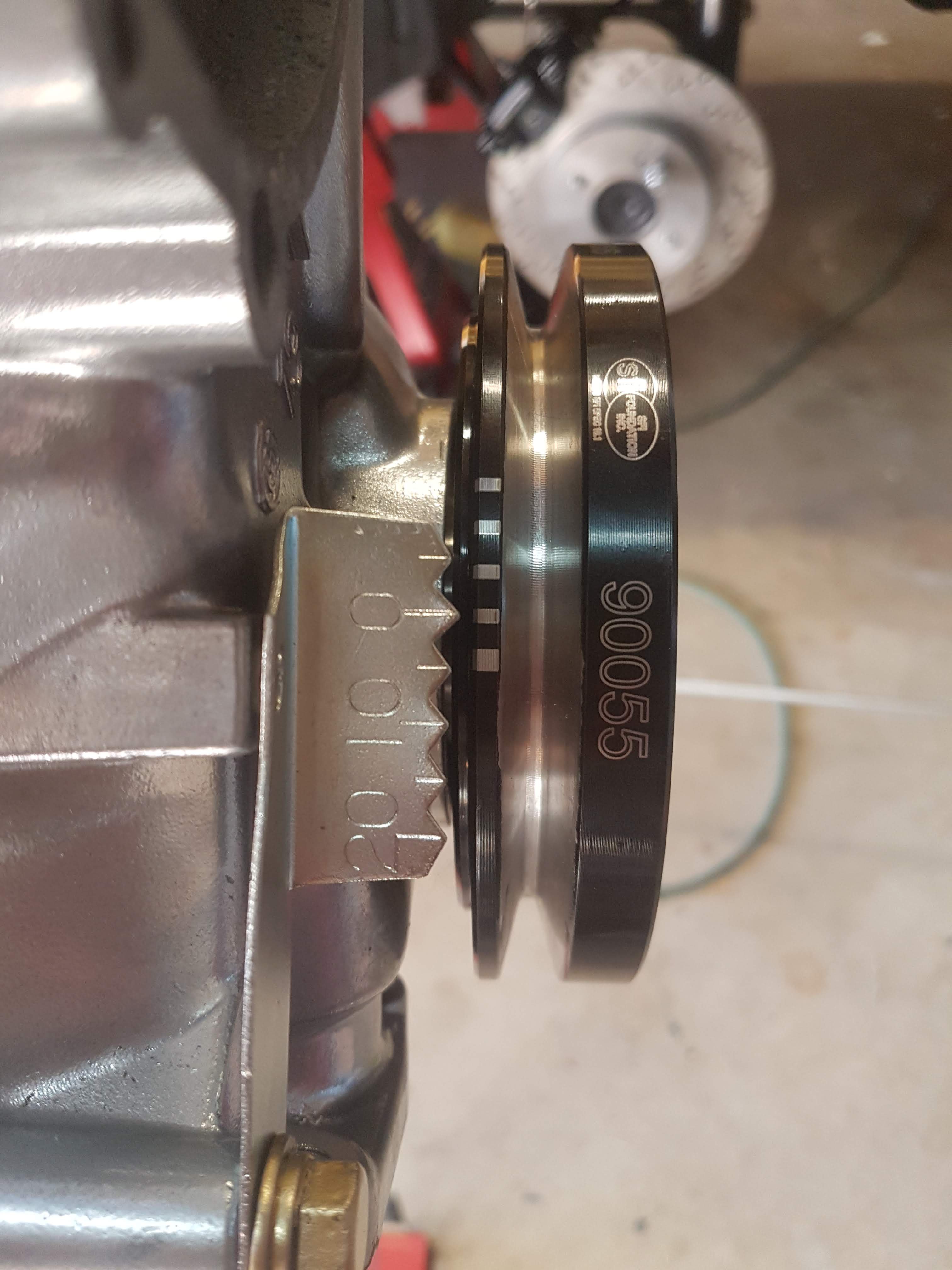
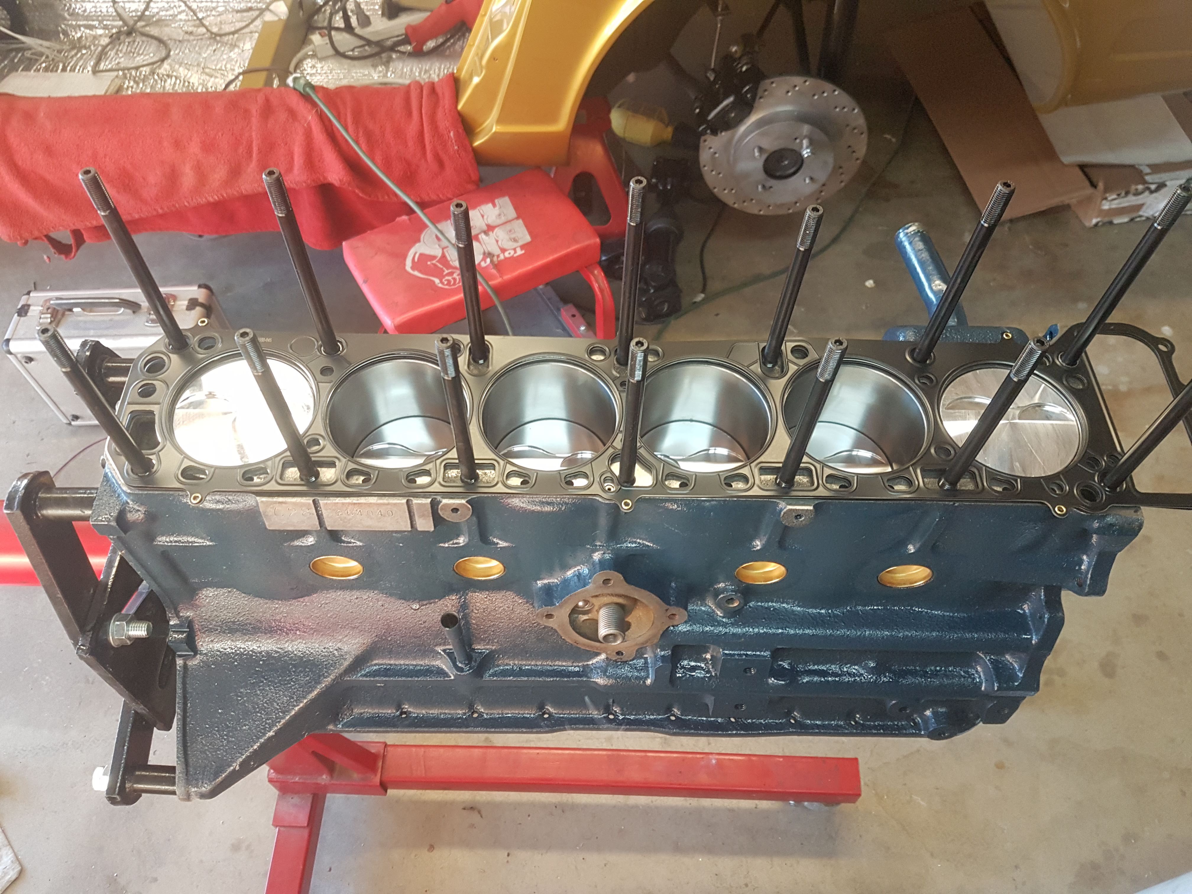
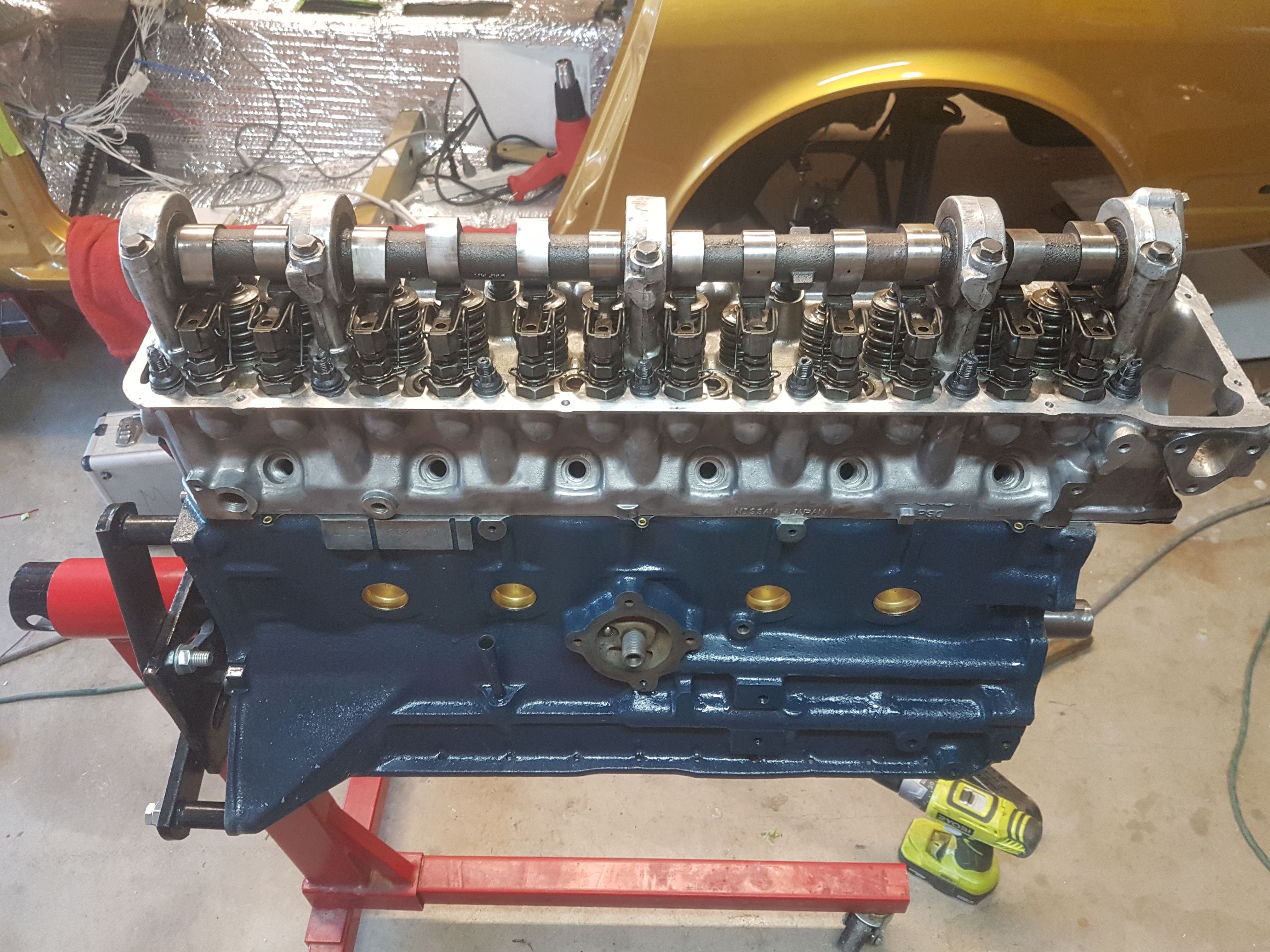
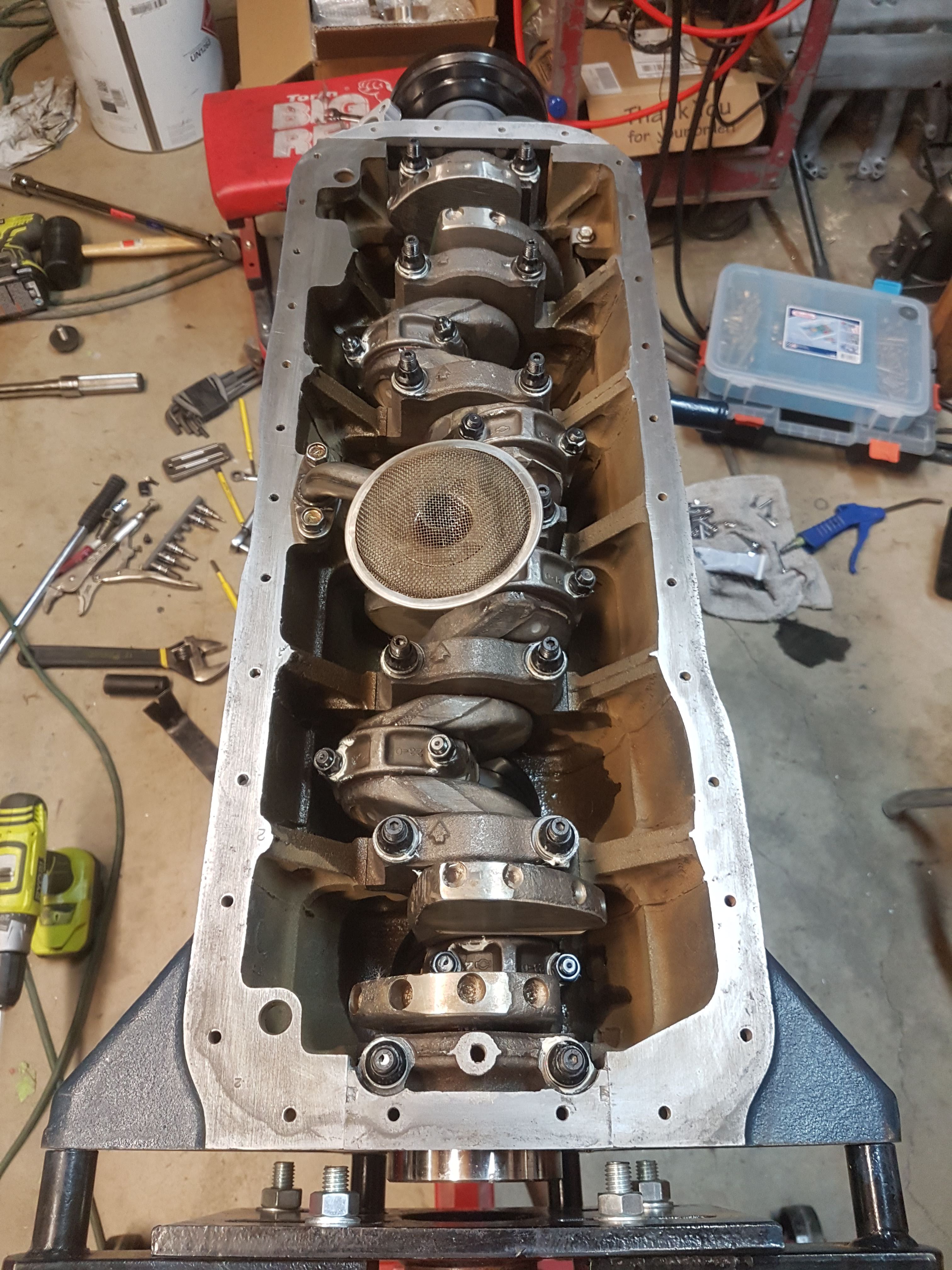
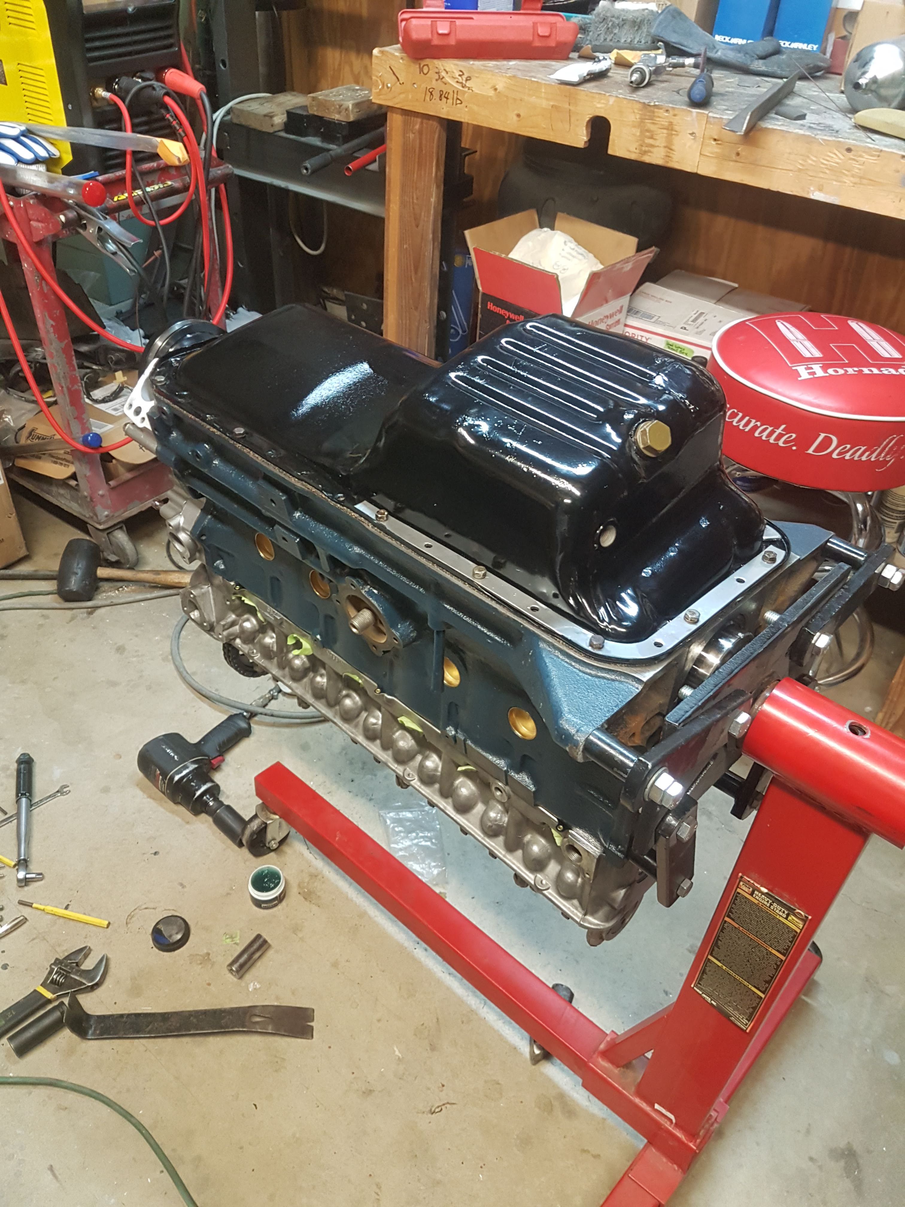
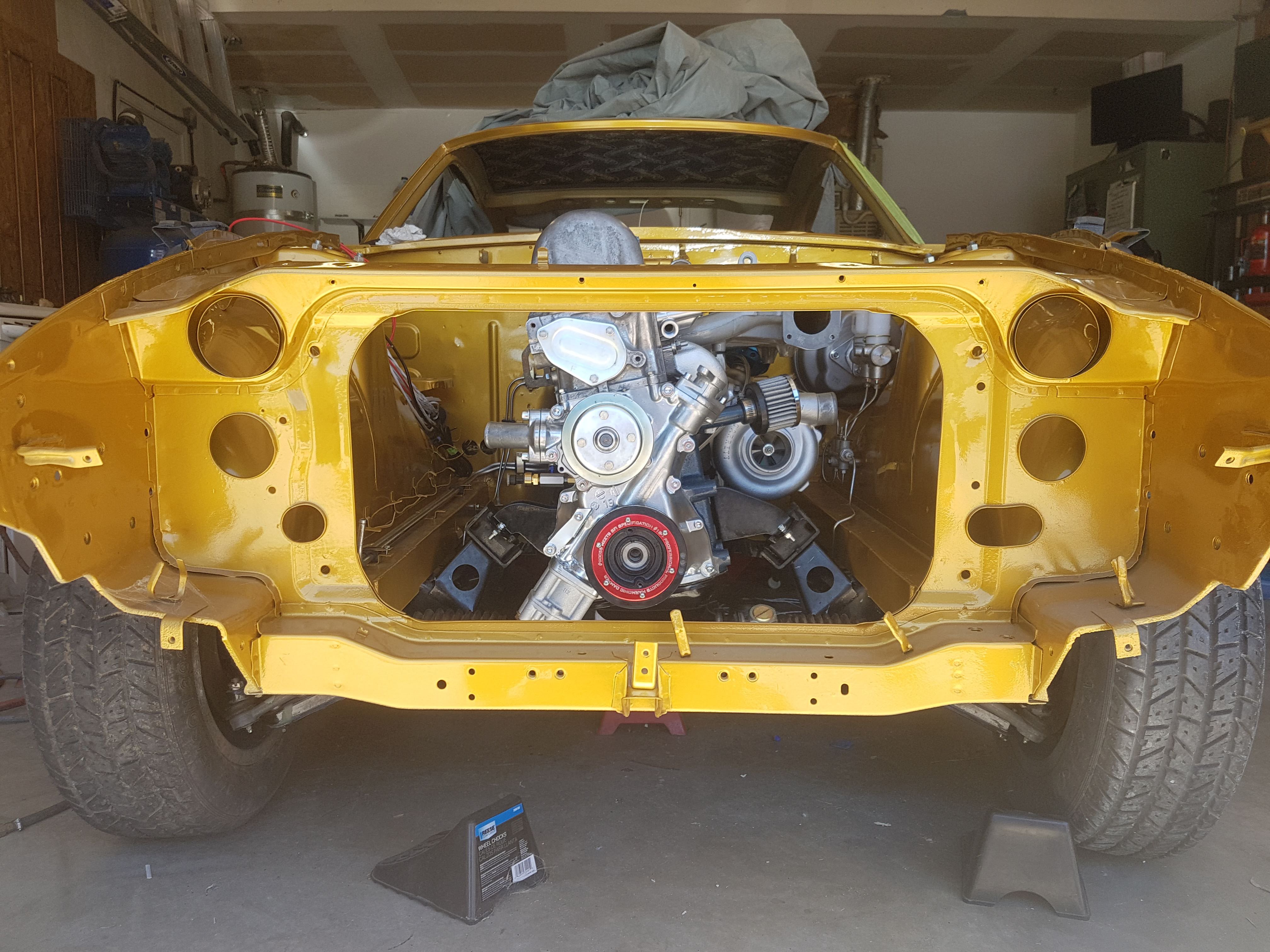
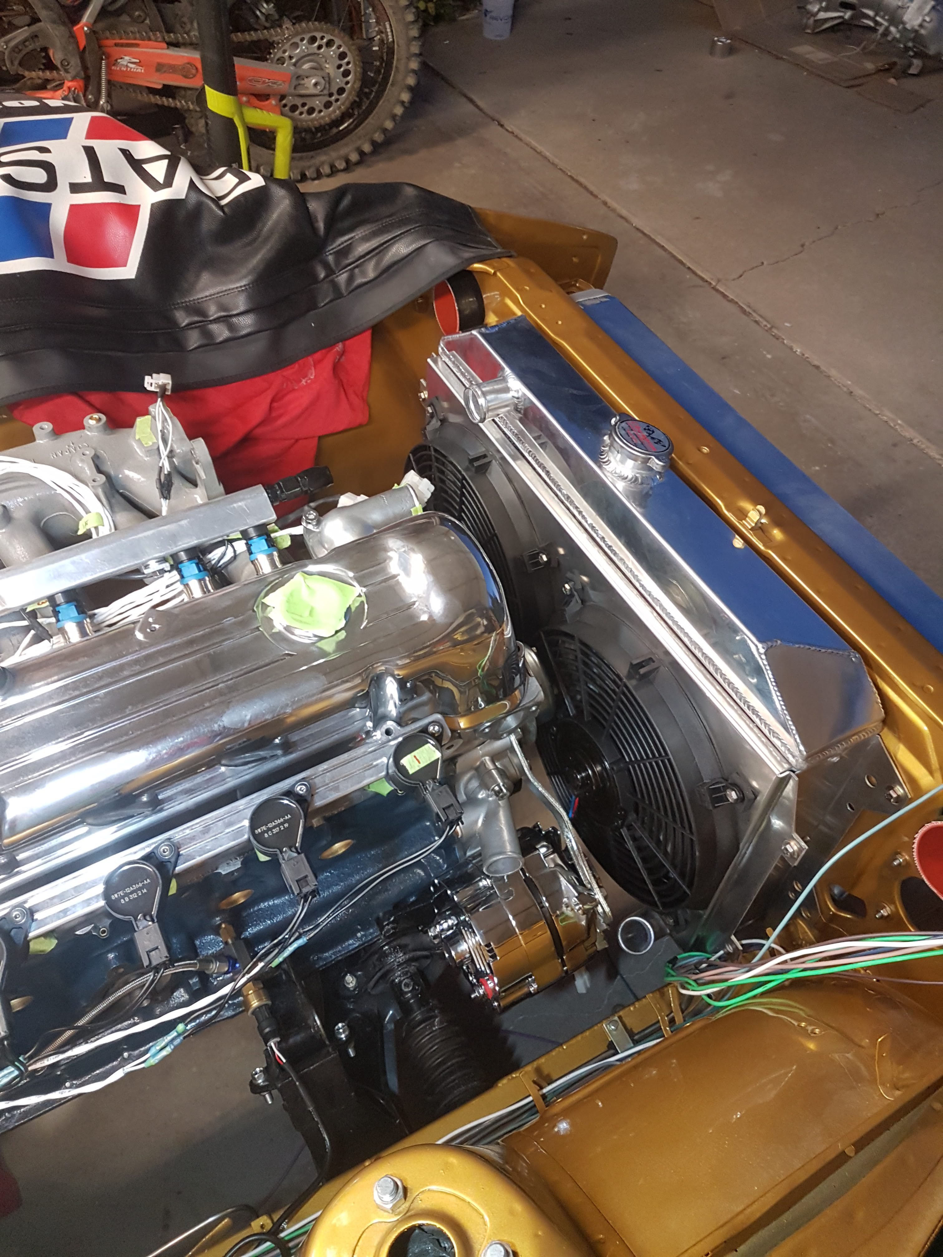
Wow it's been a long time since I've posted. I've been working hard on the Megasquirt 3 with COP and full sequential. I've also been working on the interior, dash, etc. Here's a quick break down of what I've done since the last update:
New VintageDash Dash is assembled with SpeedHut gauges
Bored the engine to 87mm
Moly coated JE Forged pistons with contact reduction and accumulator grooves
ARP rod, main, and head bolts/studs installed
New timing components installed
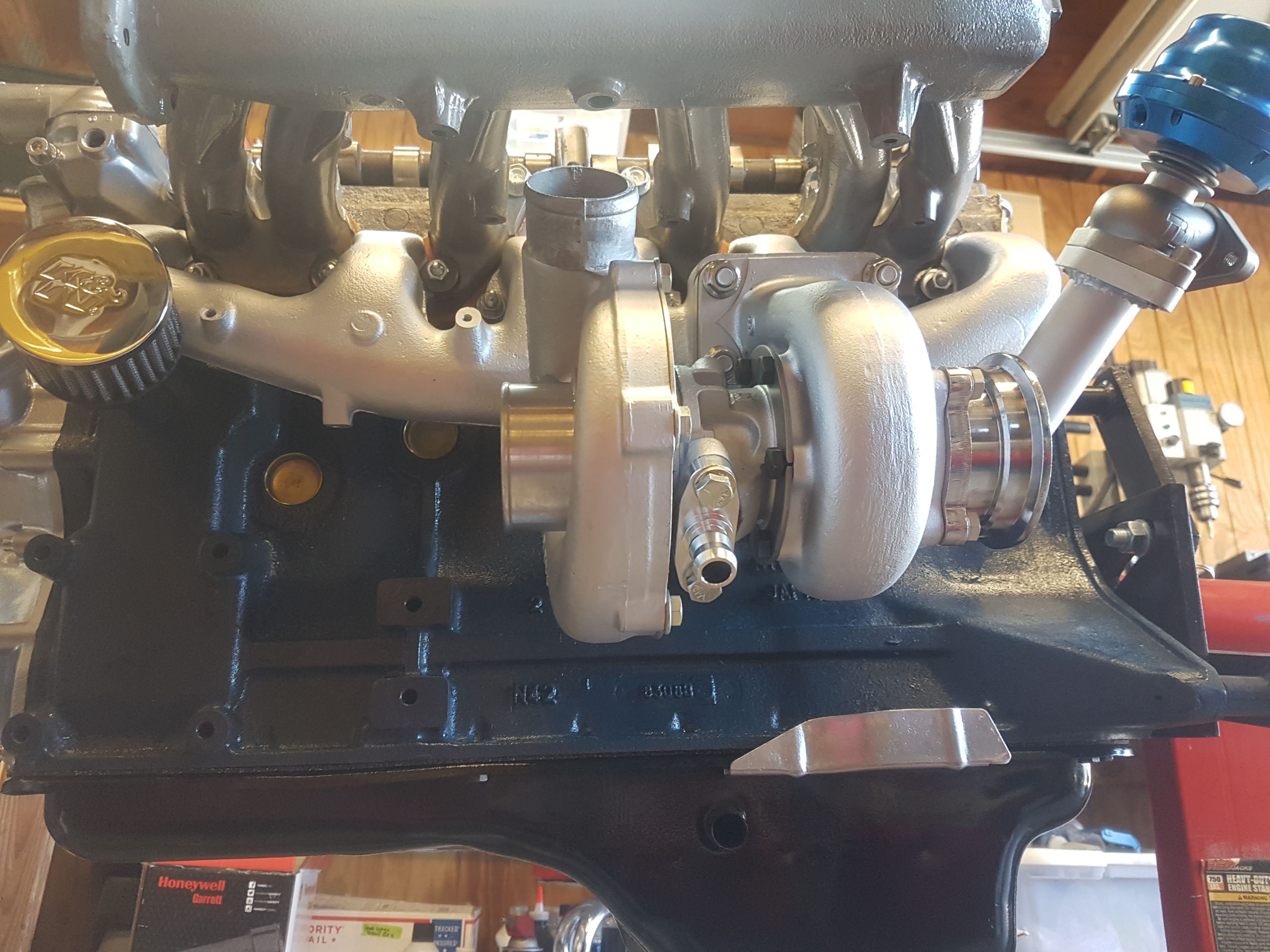
Turbo oil pump installed
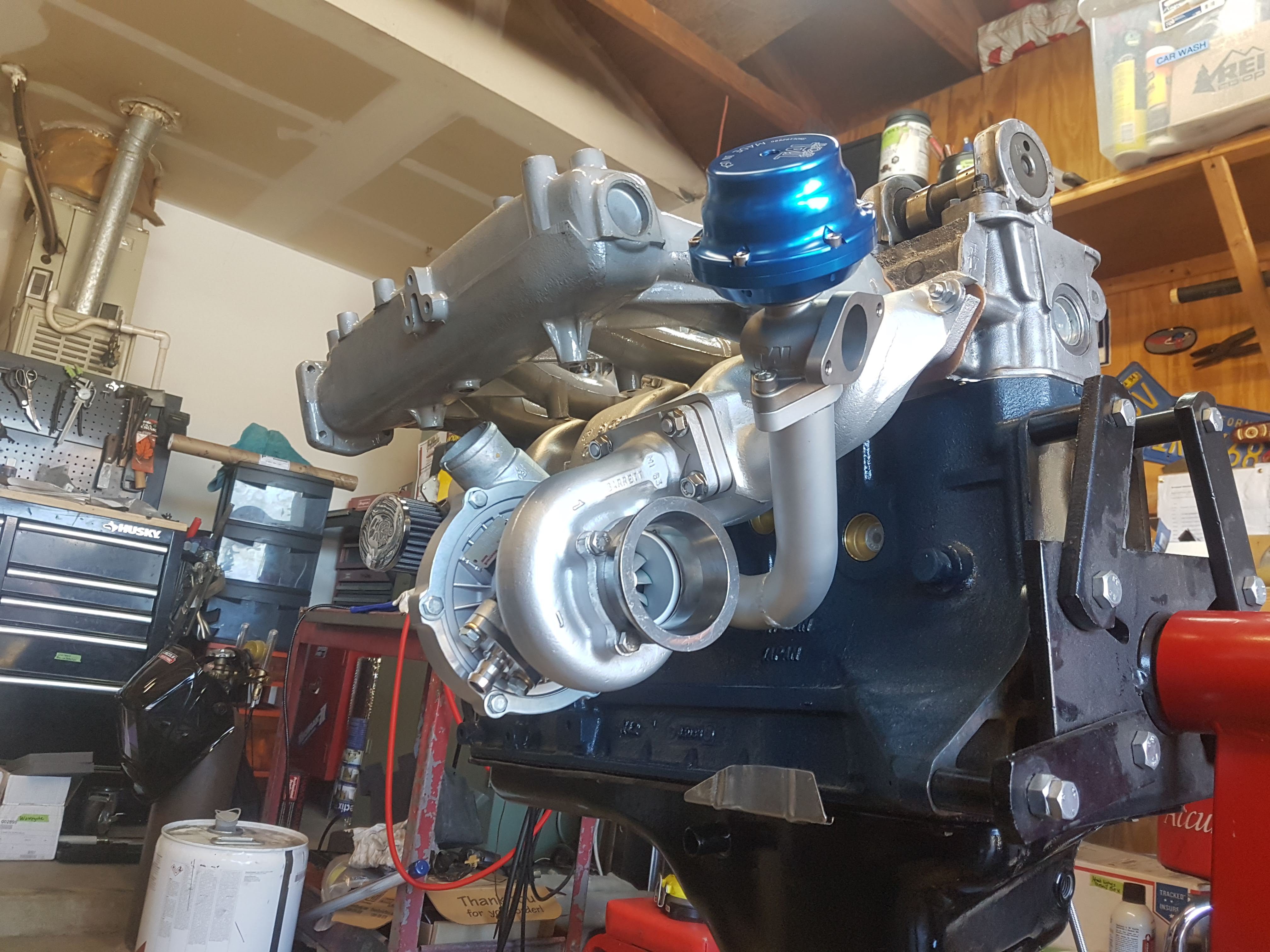
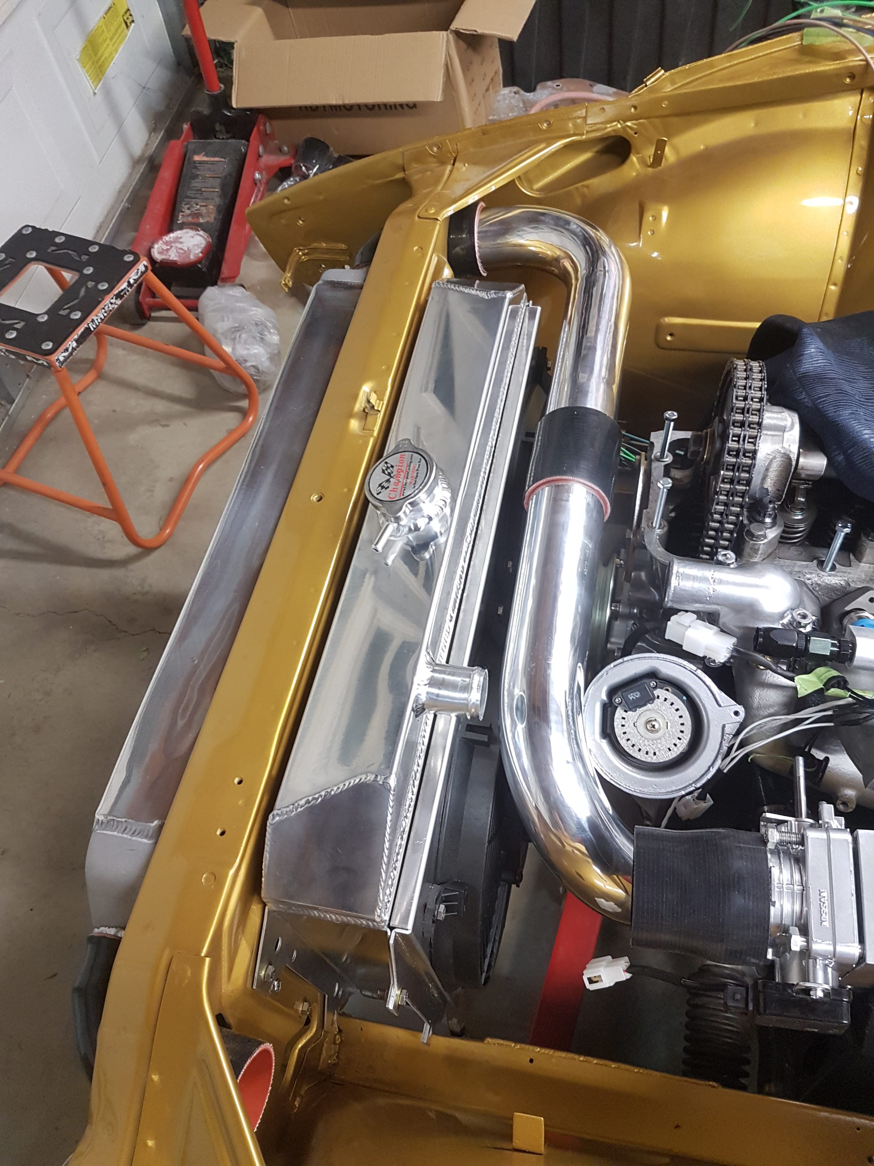
T3/T04E Garret Turbo 50Trim 0.63A/R. Ceramic coated.
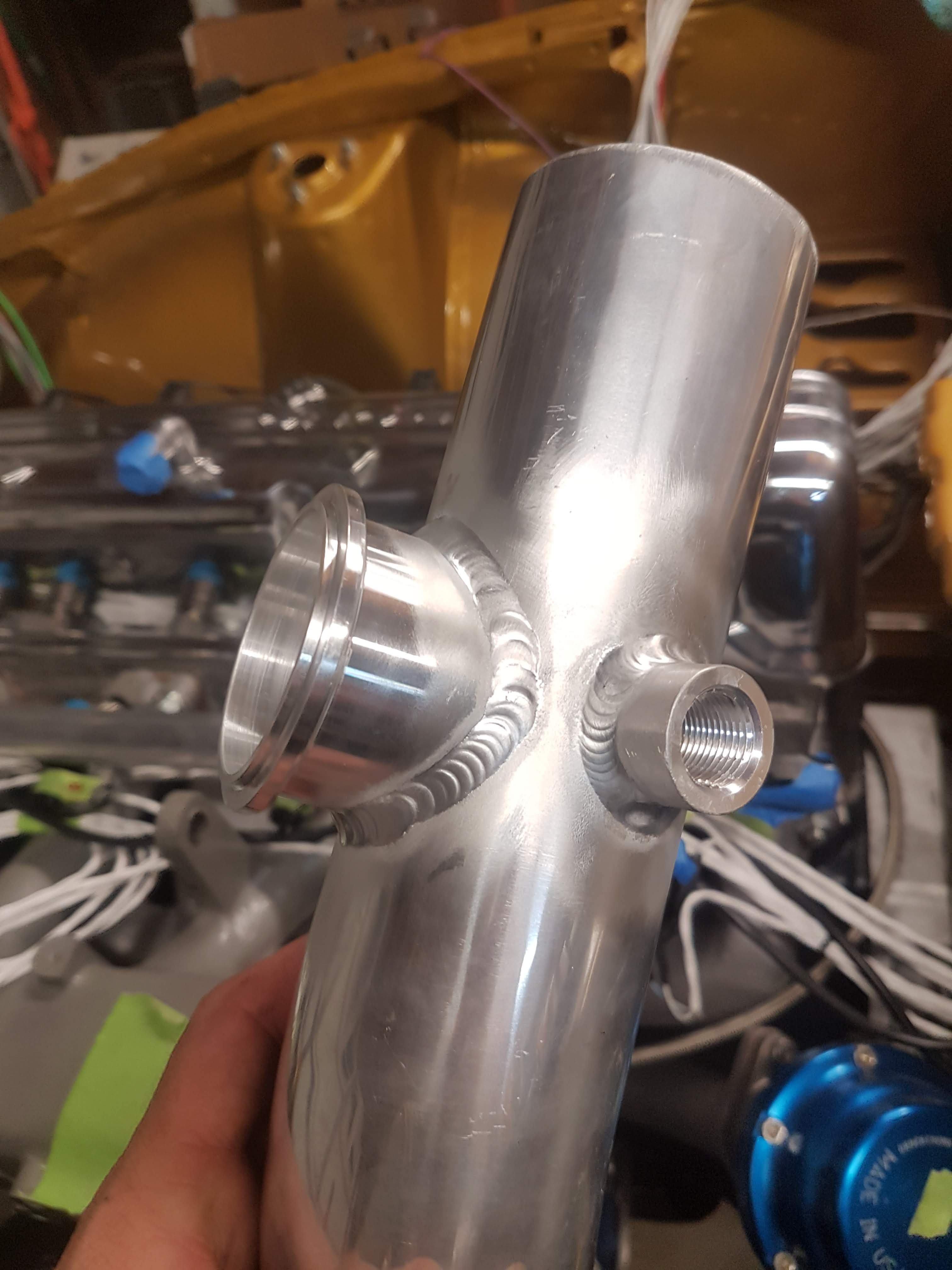
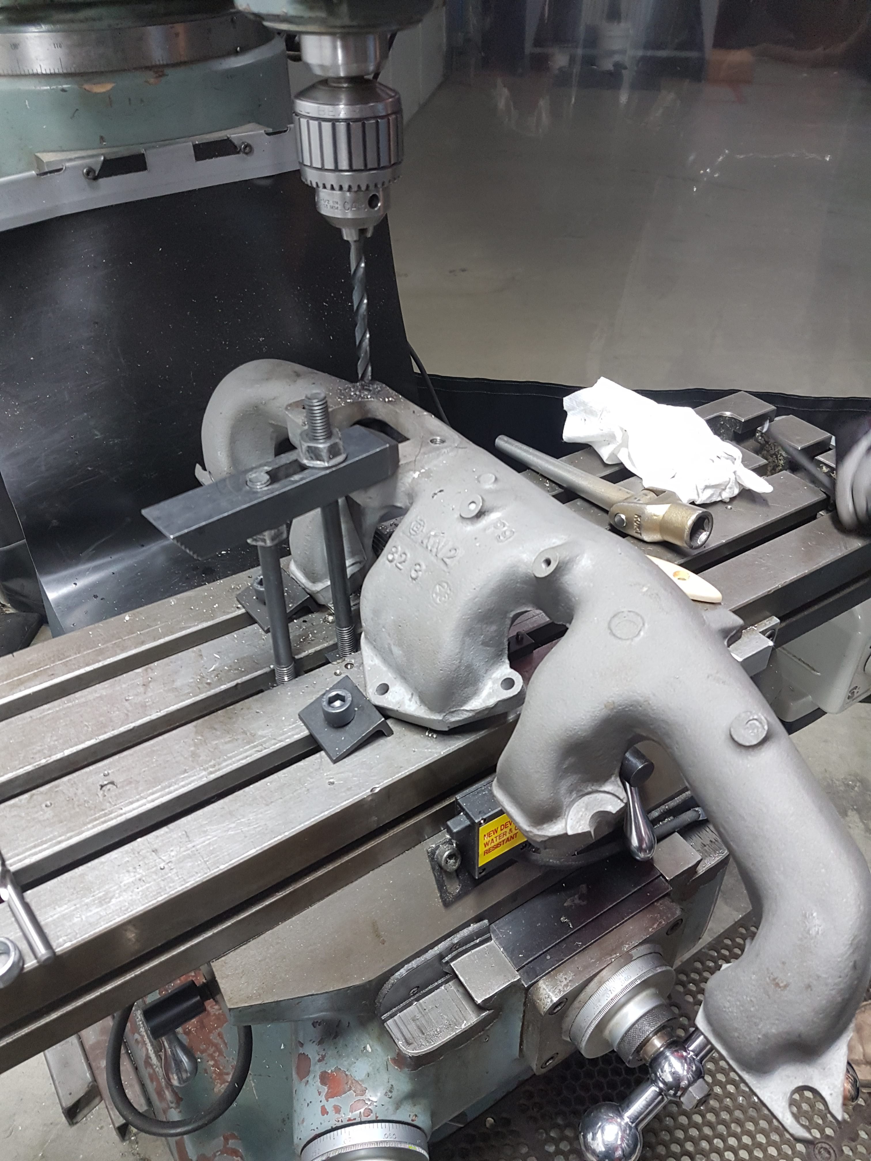
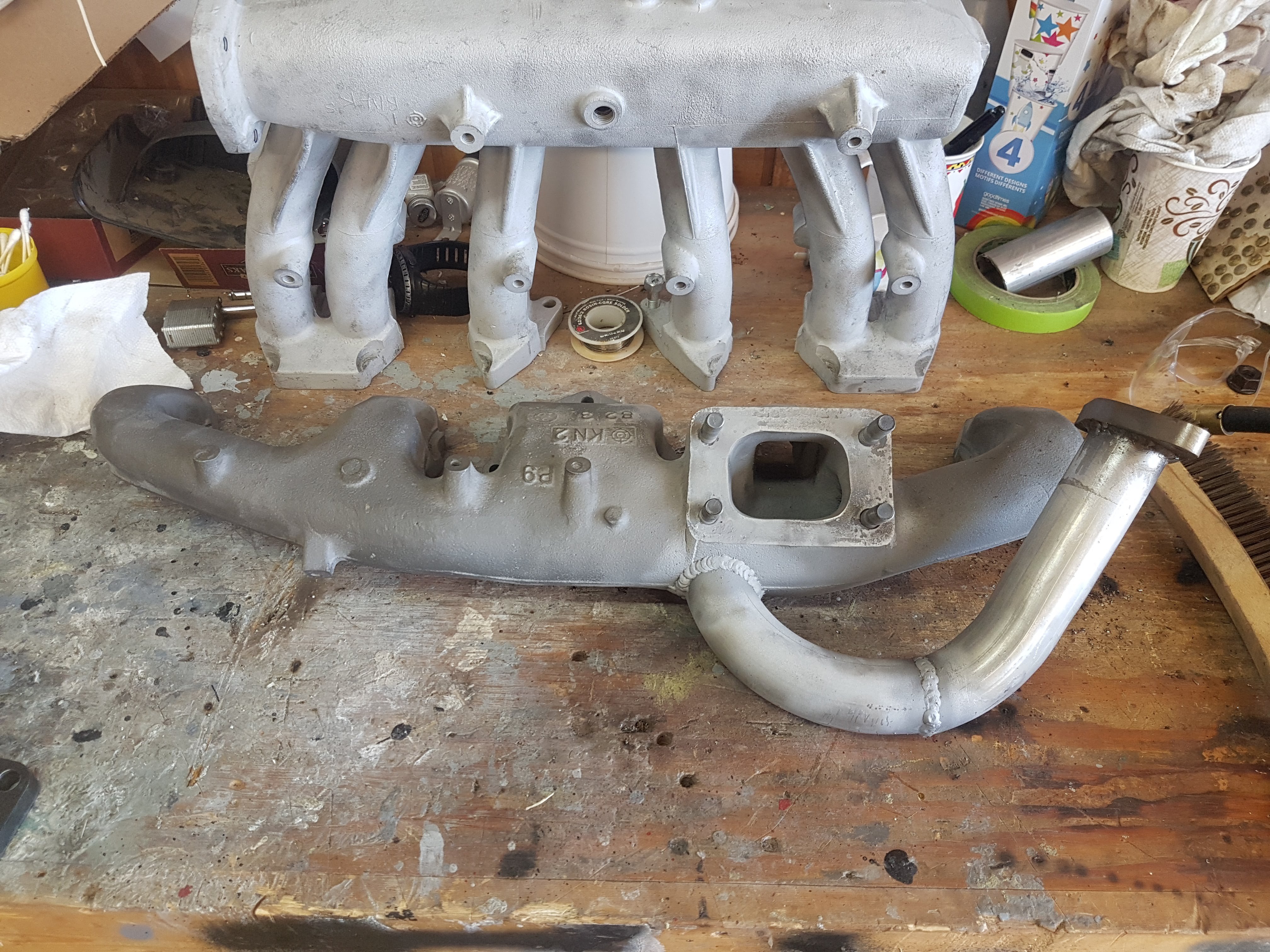
Ceramic coated exhaust header with external wastegate piping
TiAL BOV and Wastegate install
Treadstone Intercooler install
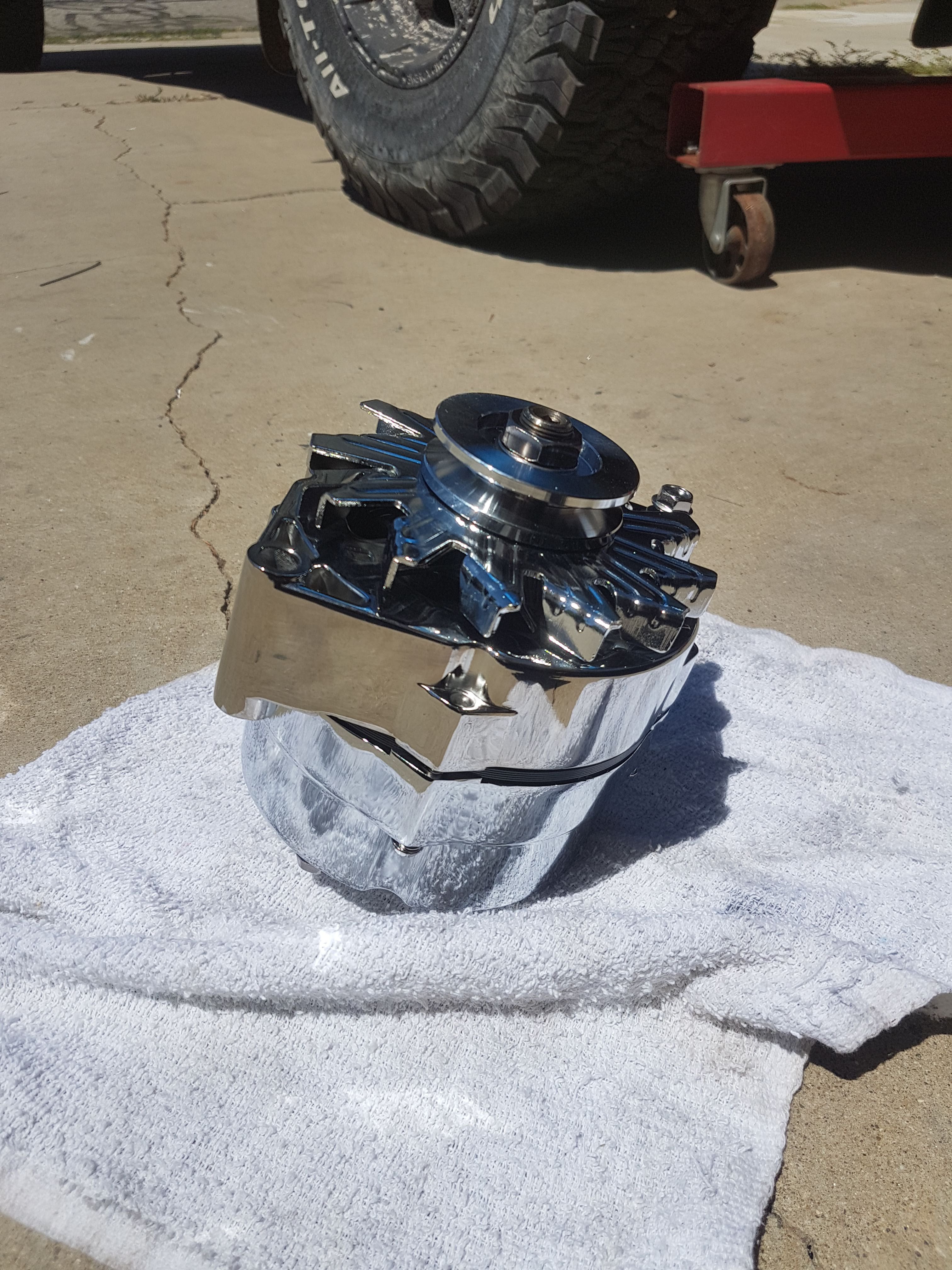
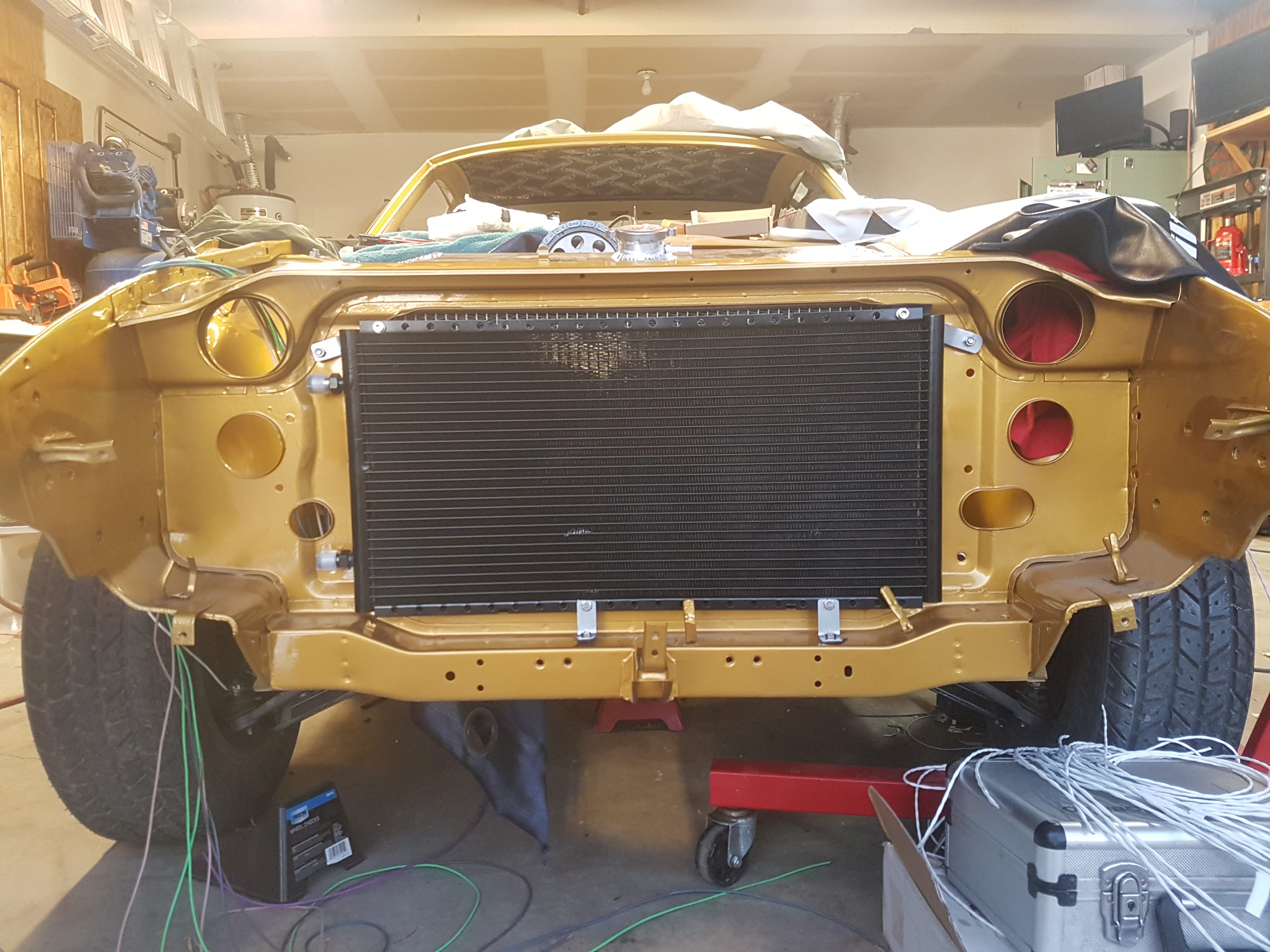
Champion 4-row radiator installed
Twin 12" electric fan install
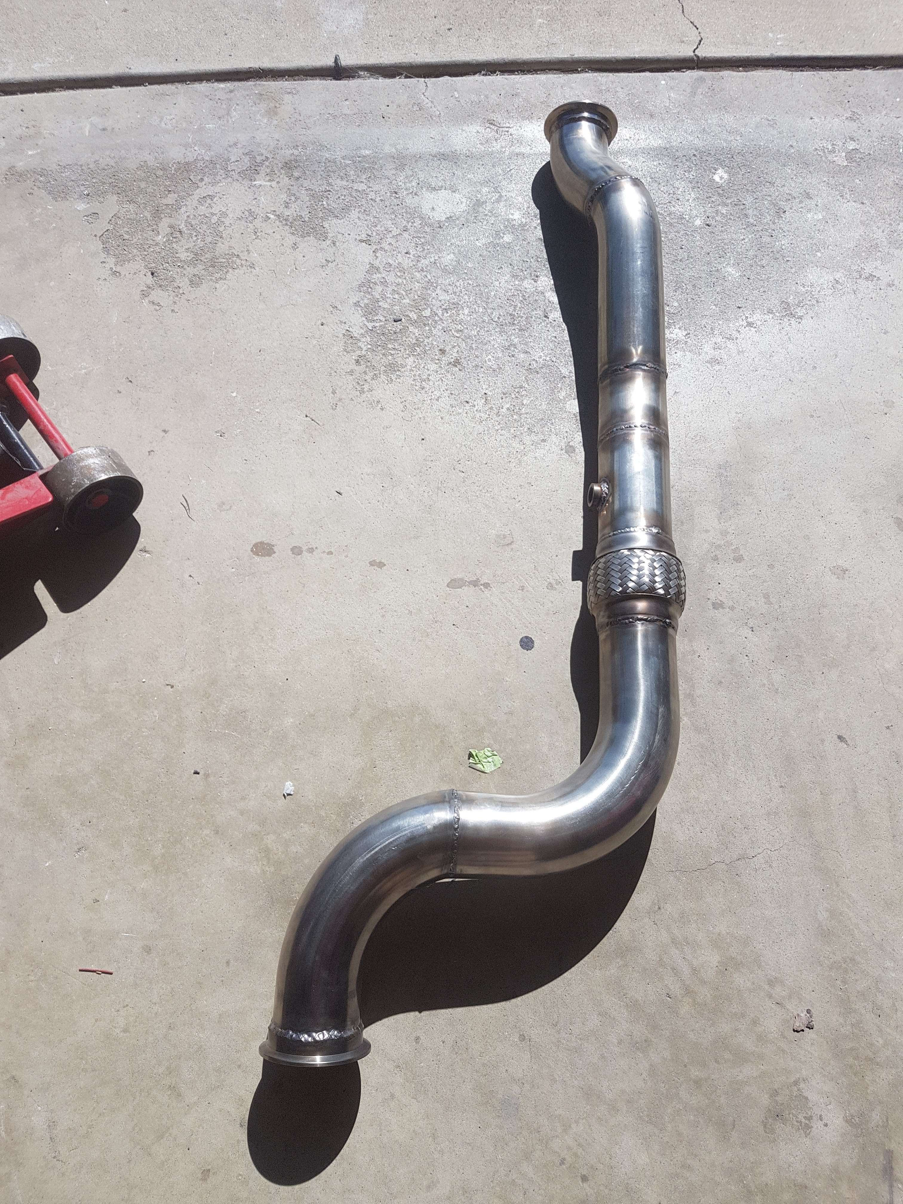
3" stainless steel exhaust from turbo back. Custom welded.
Wideband O2 installed in exhaust
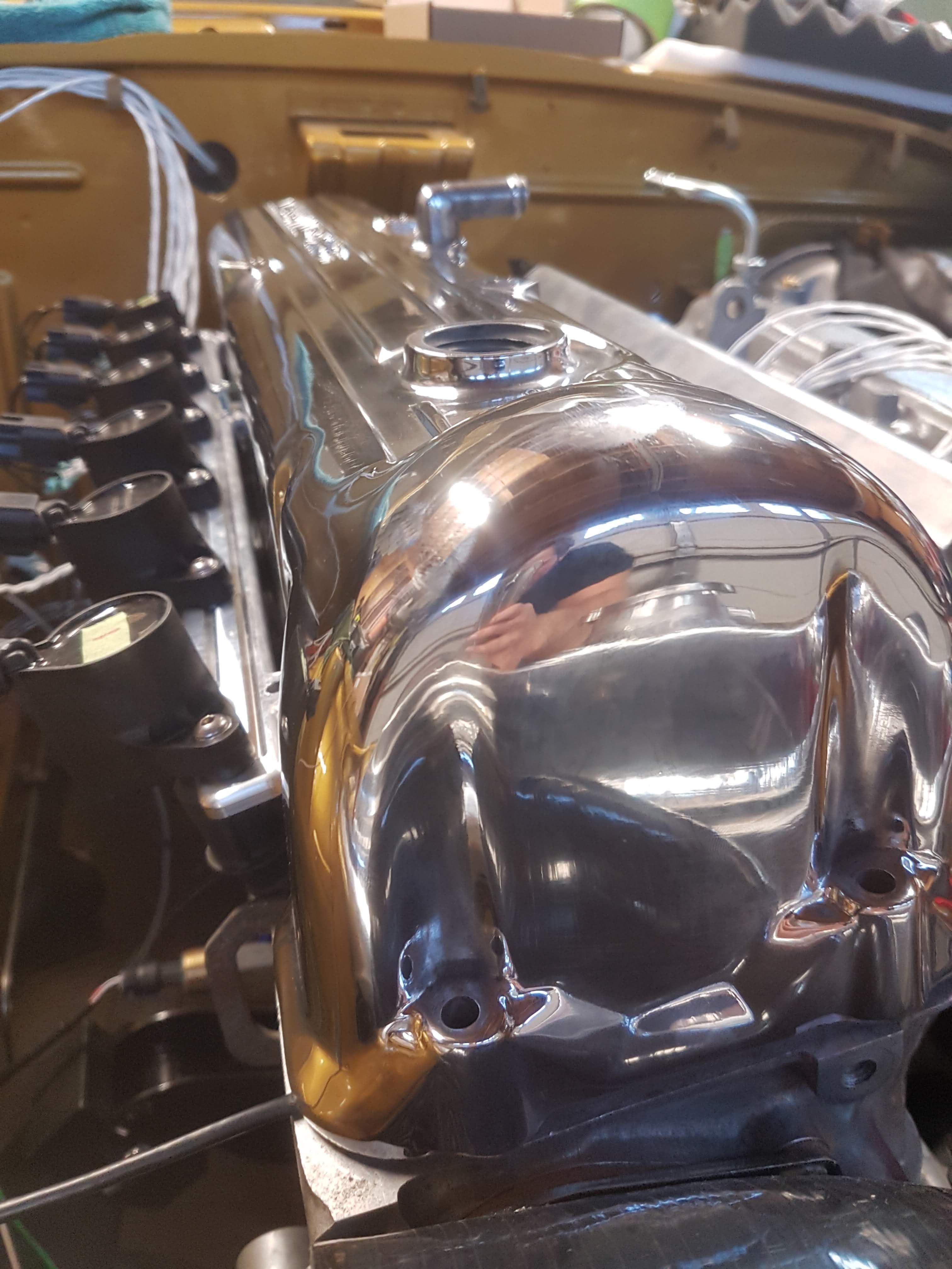
DG508 coils installed
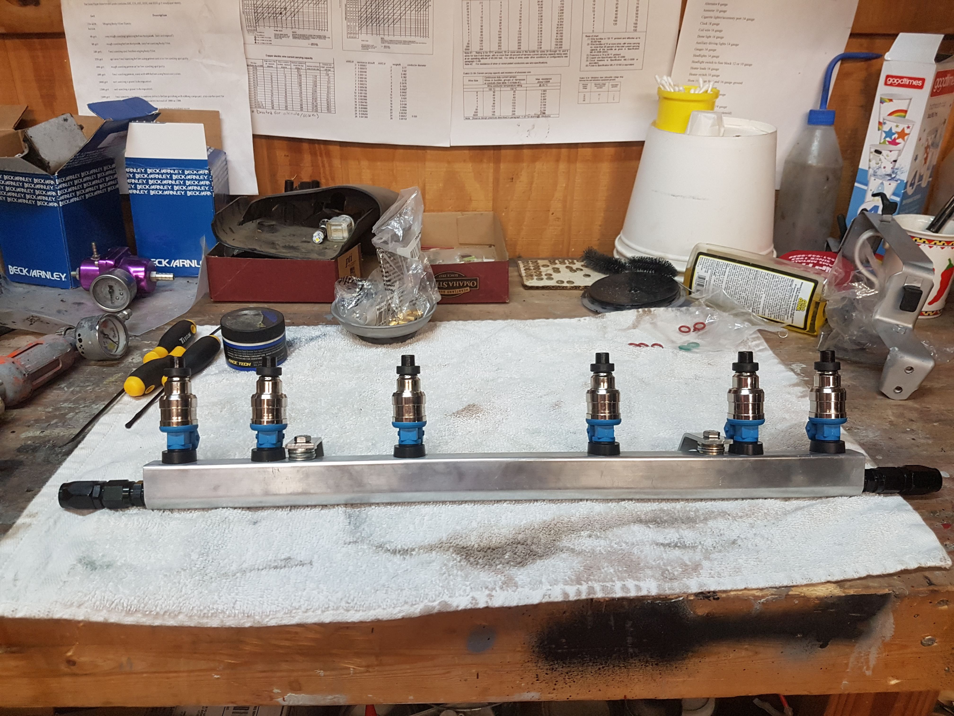
Palnet fuel rail installed
RRFPR installed
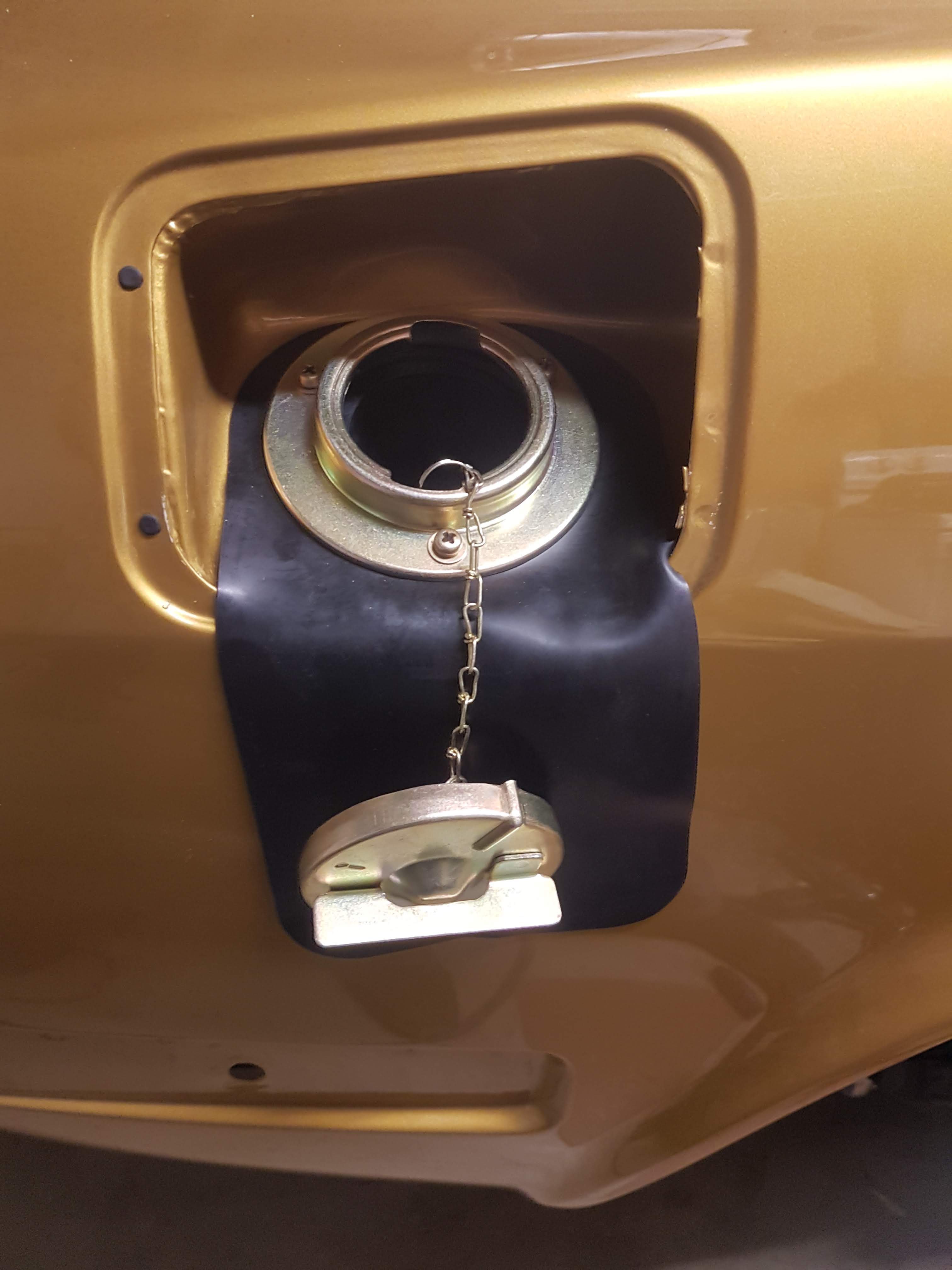
Gas tank installed
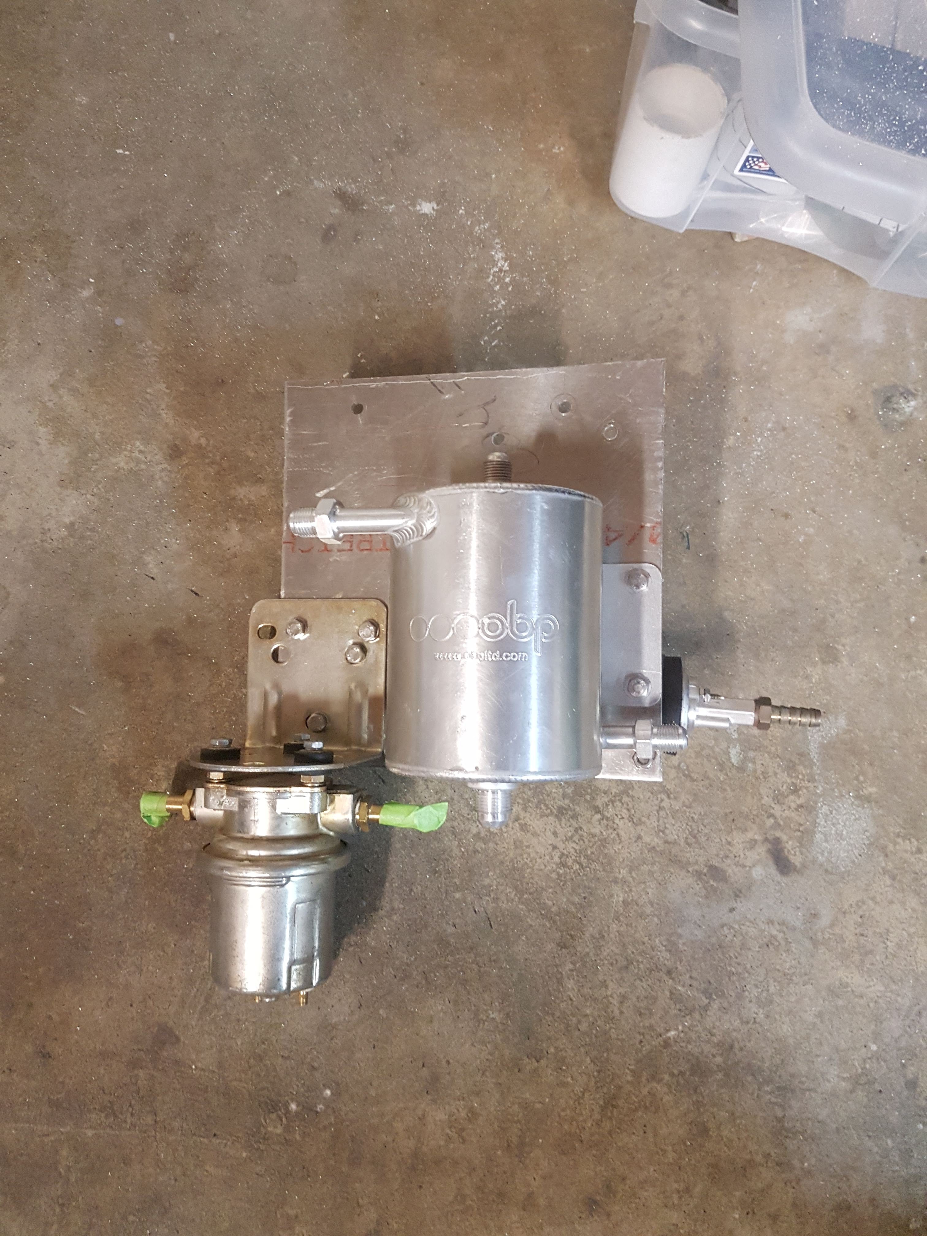
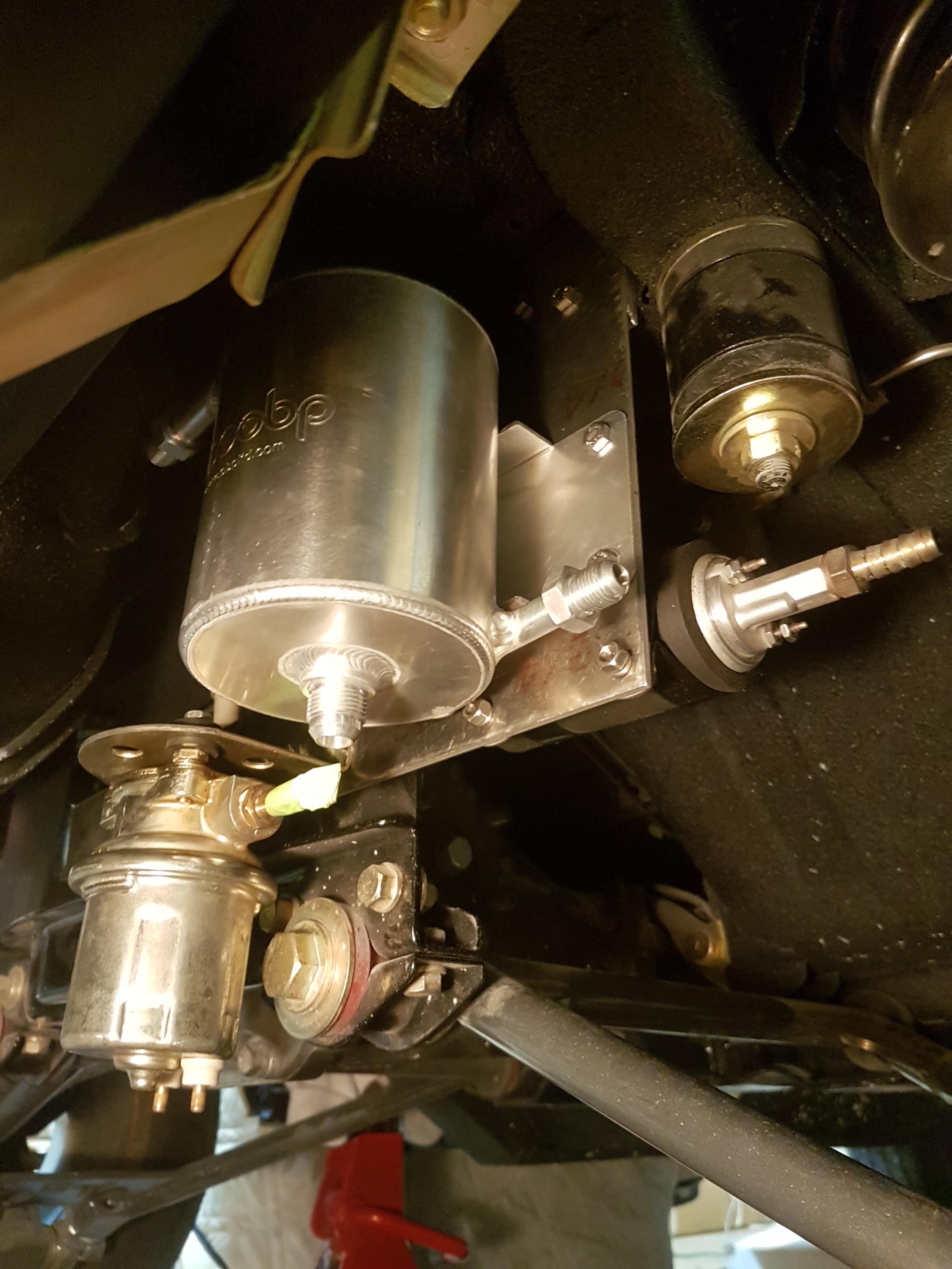
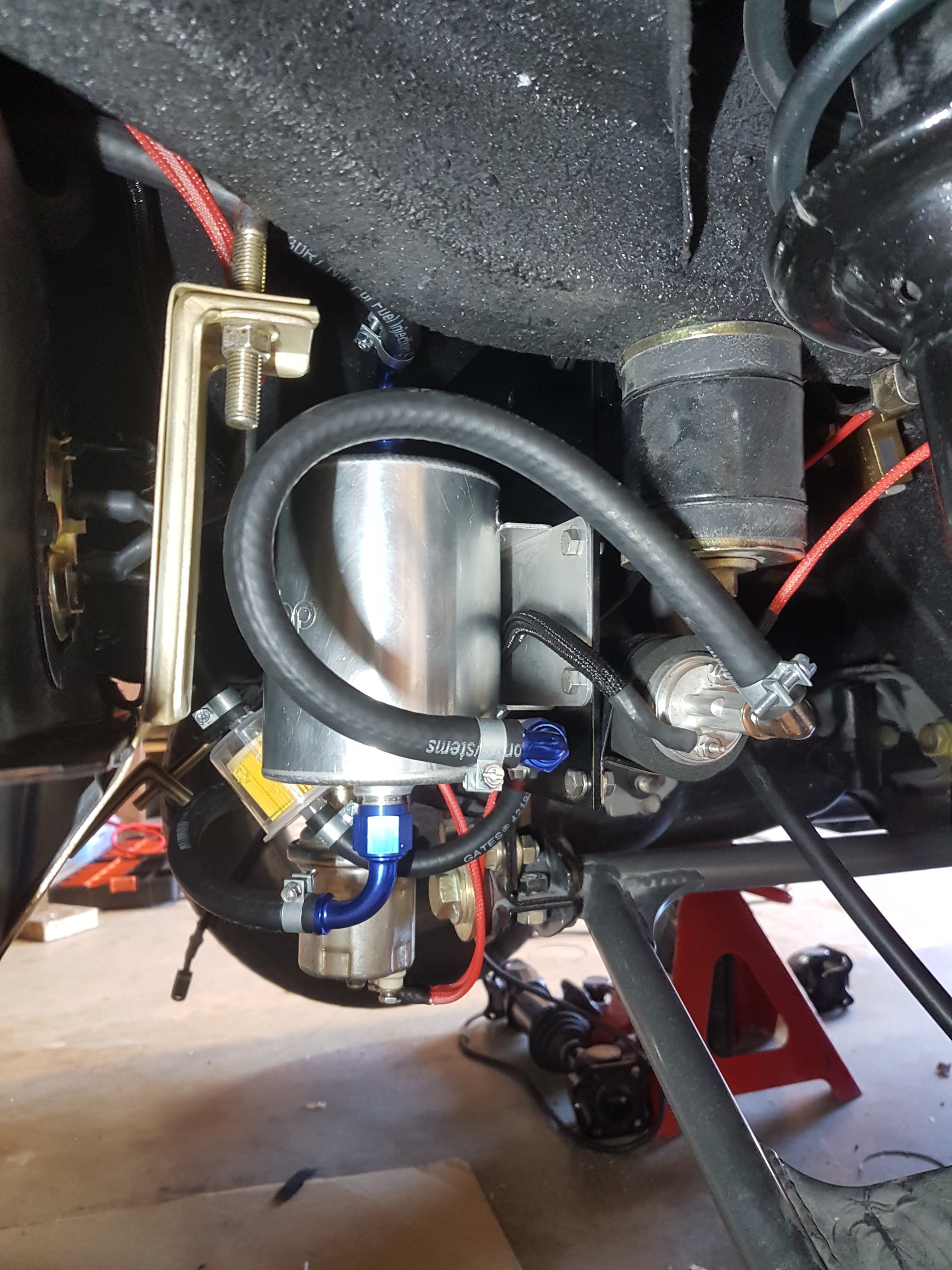
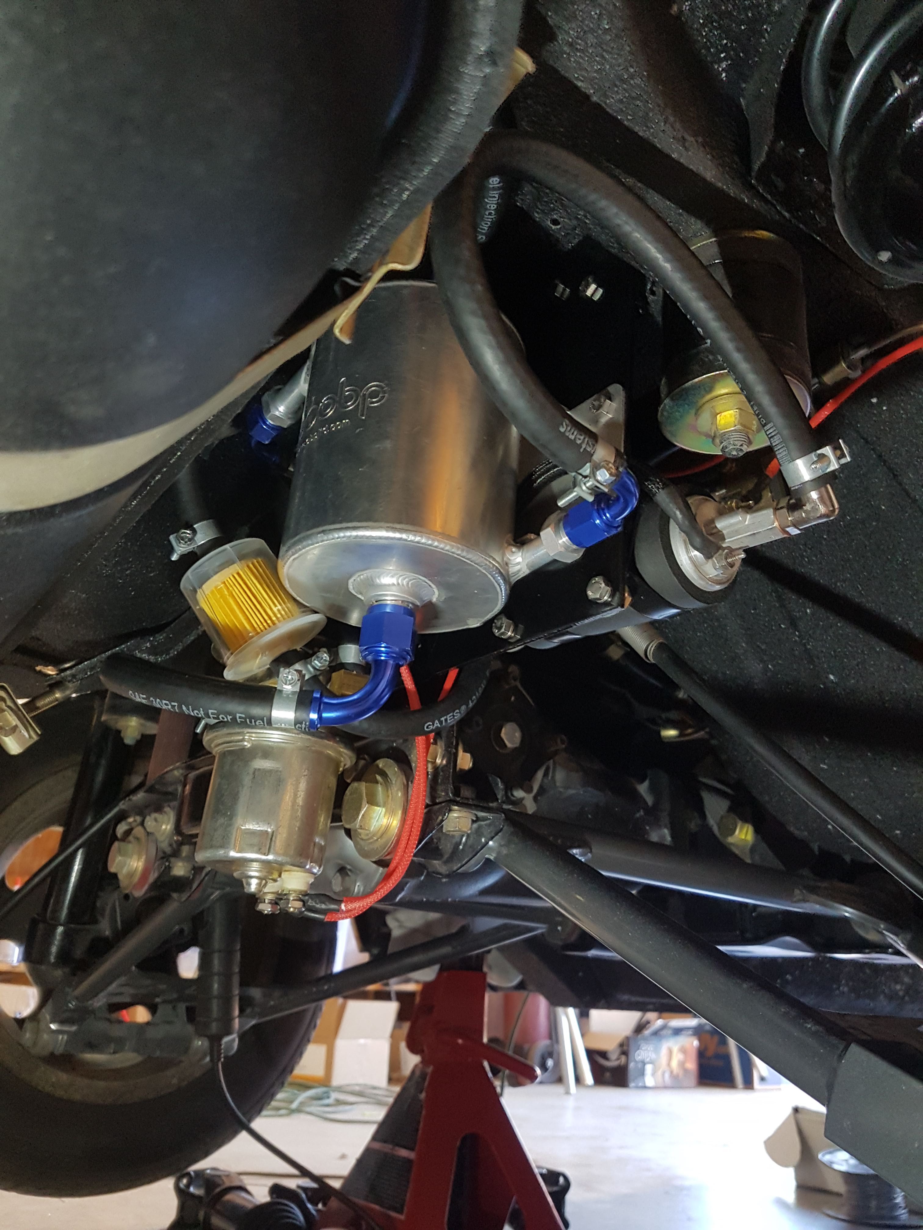
Fuel surge tank installed
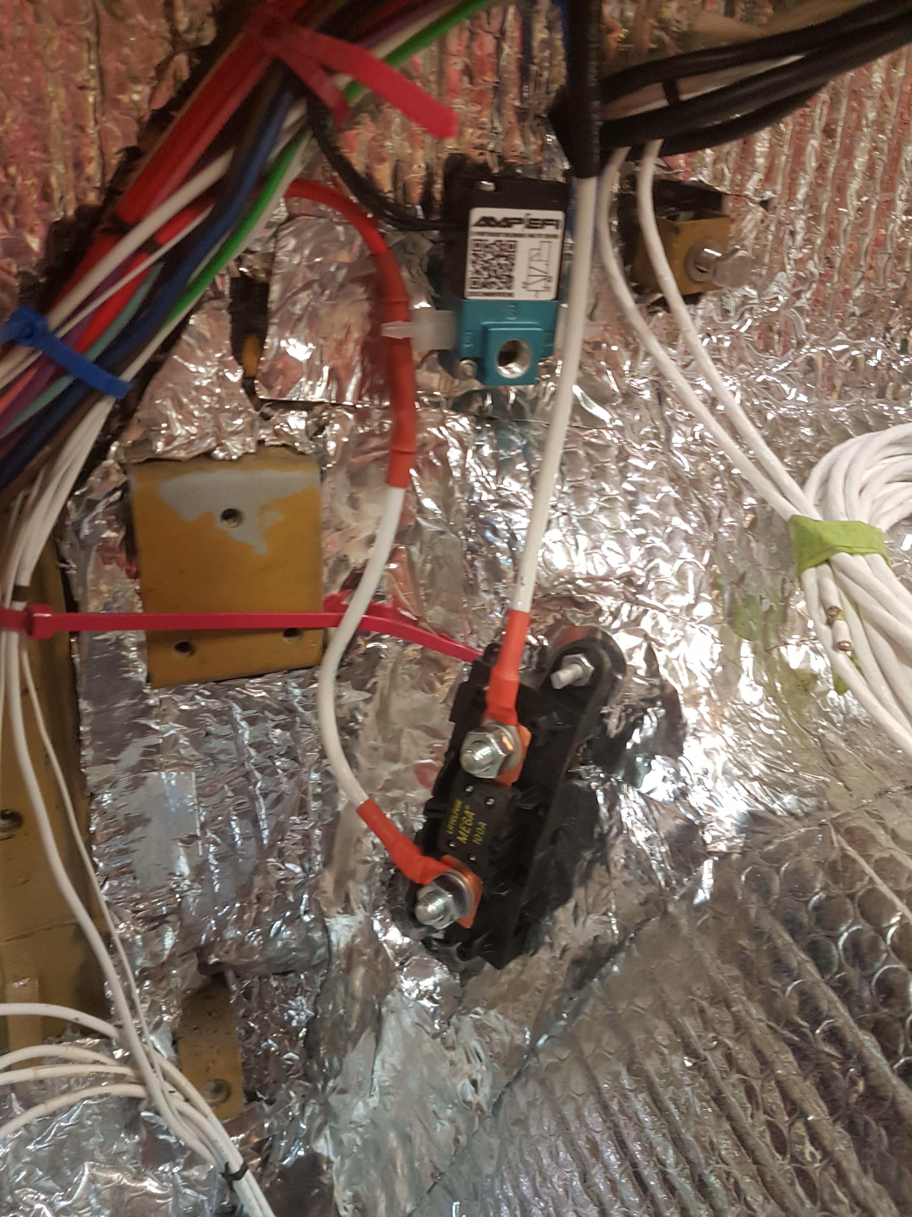
Carter P4070 lift pump and Walbro GSL39 primary fuel pump installed
Classic Tube stainless steel fuel hardlines installed from
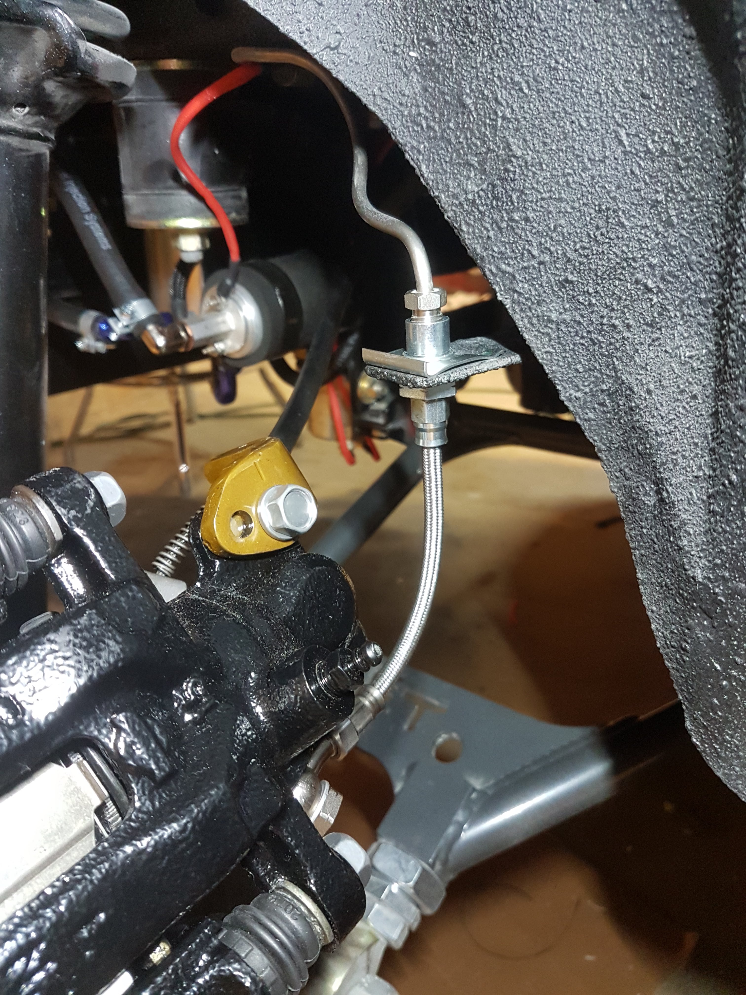
Classic Tube stainless steel brake lines installed
Custom fabricated braided SS brake lines
Installed brake booster
Installed brake master cylinder
Installed clutch master cylinder
Installed E-brake cable
Engine run at idle on full sequential and COP
Reflectix heat shield installed on interior
Leather diamond stiched vinyl installed
-
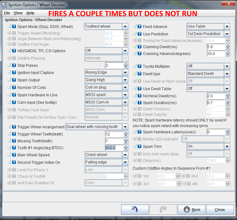
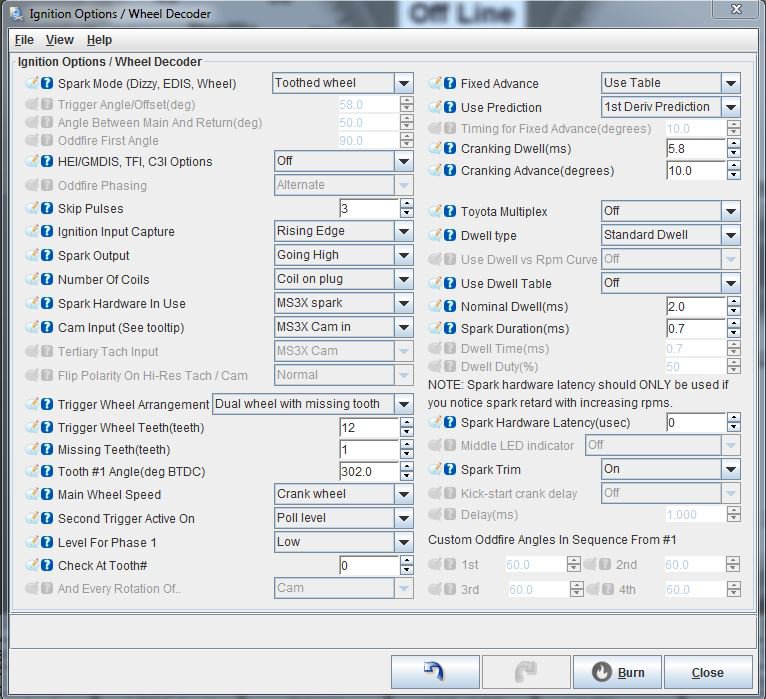
I tried adding 360 degrees to the tooth 1 angle to put the cam in the other phase per Matt Cramer's suggestion. This seemed to get rid of the cam fault during cranking, but now the engine will not start. The engine only starts with Second Trigger set to Poll Level in Full Sequential/COP but always has the cam fault. I've tried the other 4 combinations of Ignition Input Capture and Second Trigger Active On and the engine will not start. It fires a few times but then dies.
I've tried adjusting the required fuel up and down as well as the VE table and I still can't get it to start.
-
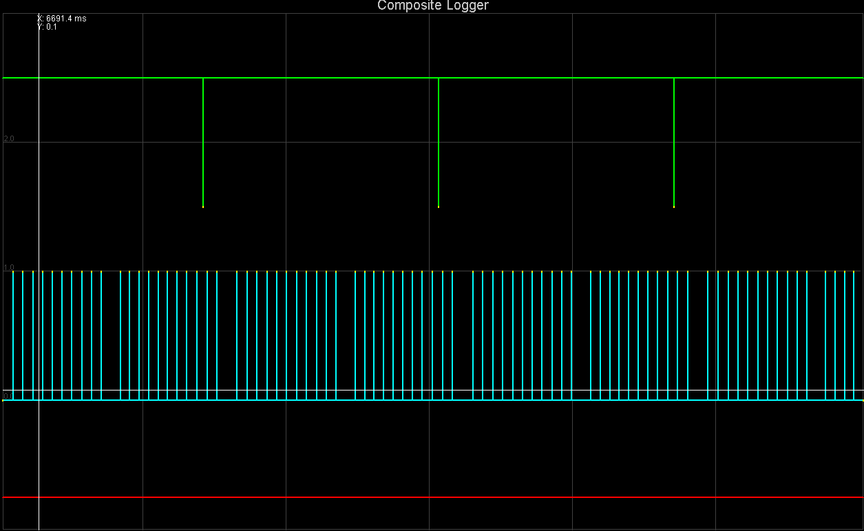
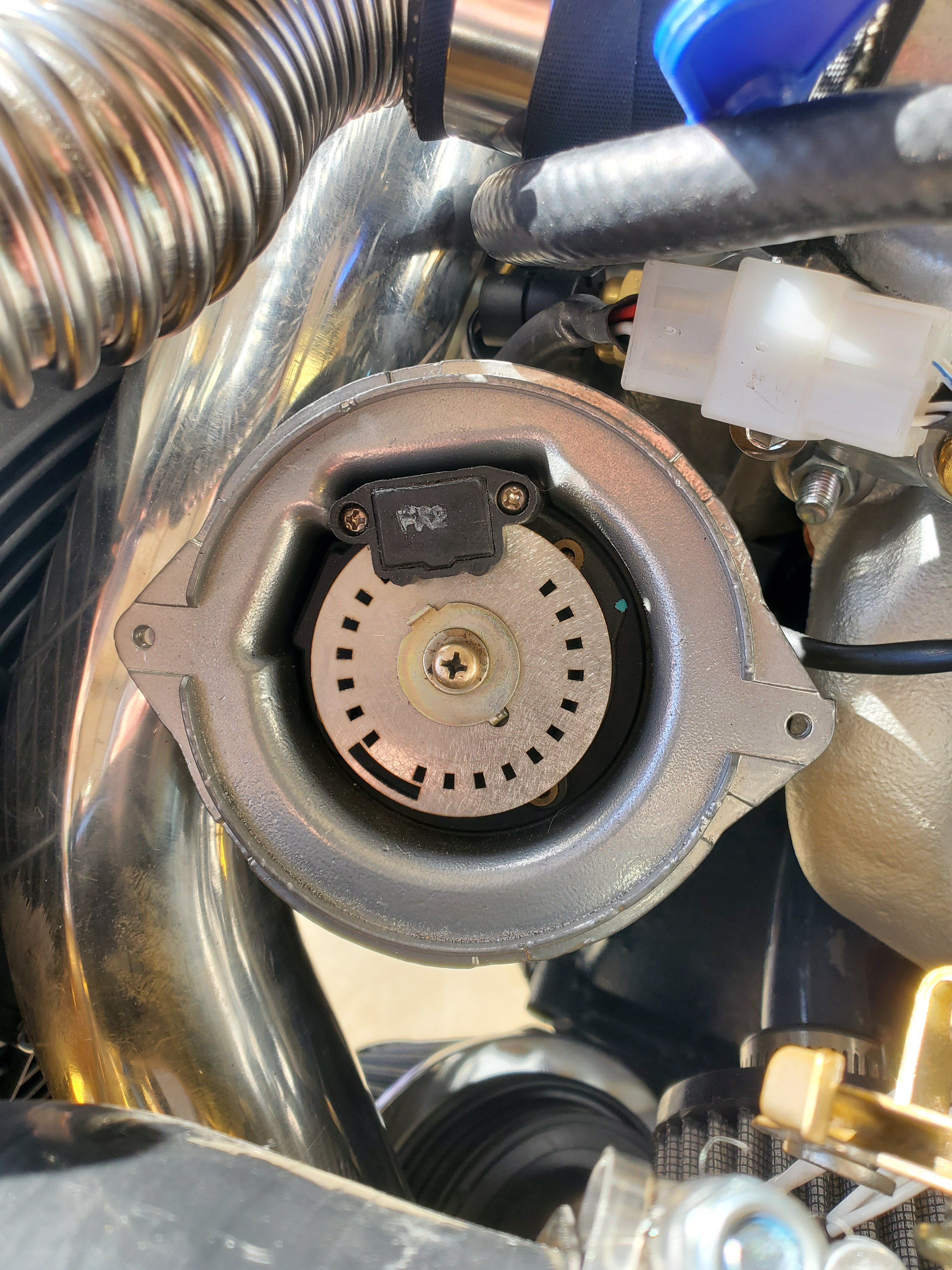
Hey y'all,I'm a little stuck on the cam fault issue I'm having in Tuner Studio. Here's my setup:Turbo Datsun 240zFull Sequential/Coil On Plug440cc Supra InjectorsDIYAutoTune CAS Wheel in an '83 280zx DistributorIATMAPWideband LC-2DG508 CoilsPowerforce DamperI went through all of the checkouts in the manual using the JimStim and JimStimX. Using the JimStimX, though, the correct setting for 'Second Trigger Active On' ended up being Falling Edge. When I installed the MS3 in the car I can only get it running with 'Second Trigger Active On' set as Poll Level. It idles but I get a Cam Fault in Tunerstudio.I attached my msq and a composite log. Looking at the composite log and the physical CAS wheel it seems like the cam trigger should be aligned with the 11th tooth, but it's not.I've read elsewhere that this fault is because the cam signal is on the wrong phase. I tried switching the CAS wheel and distributor (not the shaft but the distributor itself) orientation 180 degrees to no avail.Any insight into what's going on here?
-
Still looking for a 5 speed wide ratio trans. I have 240z and 280z parts to trade if interested.


HybridZ Apparel Order Thread - 100% of Profits Will Be Donated, round 4
in Vendor's Forum
Posted
I'd buy another hoodie too. I got fat. Also, I'd buy a cap.