

gmorrone1214
-
Posts
65 -
Joined
-
Last visited
Content Type
Profiles
Forums
Blogs
Events
Gallery
Downloads
Store
Posts posted by gmorrone1214
-
-
Hello everyone, long story short my starter went bad and I replaced it with a new unit. However, when trying to start the vehicle there is only one single loud click (sounds as if the starter gear is moving out of the starter but it is not spinning the motor). I confirmed this by using a remote start and jumping the terminals, which results in the same issue, single loud click as if the starter gear is moving.
I also took off the starter cleaned the areas with a wire wheel on a dremel, and cleaned up ground wire. Still same outcome. Then I tested the voltage at the battery when activating the starter and the volts stayed at 11.8-12.4 volts.
I took the starter to autozone to check if it was functioning, which on their tester I witnessed the gear move out and spin freely 3 separate occasions.
Threw it back in and still same result. Then checked to see if the engine was frozen for some reason (was driving car prior to this), and it spins over freely.
Lost at what to do next....any help is appreciated, really trying to get this up and running with the new HY35 turbo.
-
Thank you, I appreciate the quick reply's. Not that many S130's up here in Alaska, nor S30. Debating on the manual or the power rack and pinion, I know that a lot of the power racks need rebuilds fairly often.
-
Hello everyone, I am trying to find out if a 240-280z manual rack and pinion with the cross-member will fit the S130. I want to replace the reciprocating power steering because it is leaking and I also need room for a bigger turbo upgrade.
I know that the zx also had a manual R&P, but I just found a good deal on the 240z set and need to know if it will fit the zx. -
9 hours ago, softopz said:
Have you adjusted the VR pots per manual.
Yes sir I have.
-
10 hours ago, softopz said:
Looking at your pics again I see some potential issues.
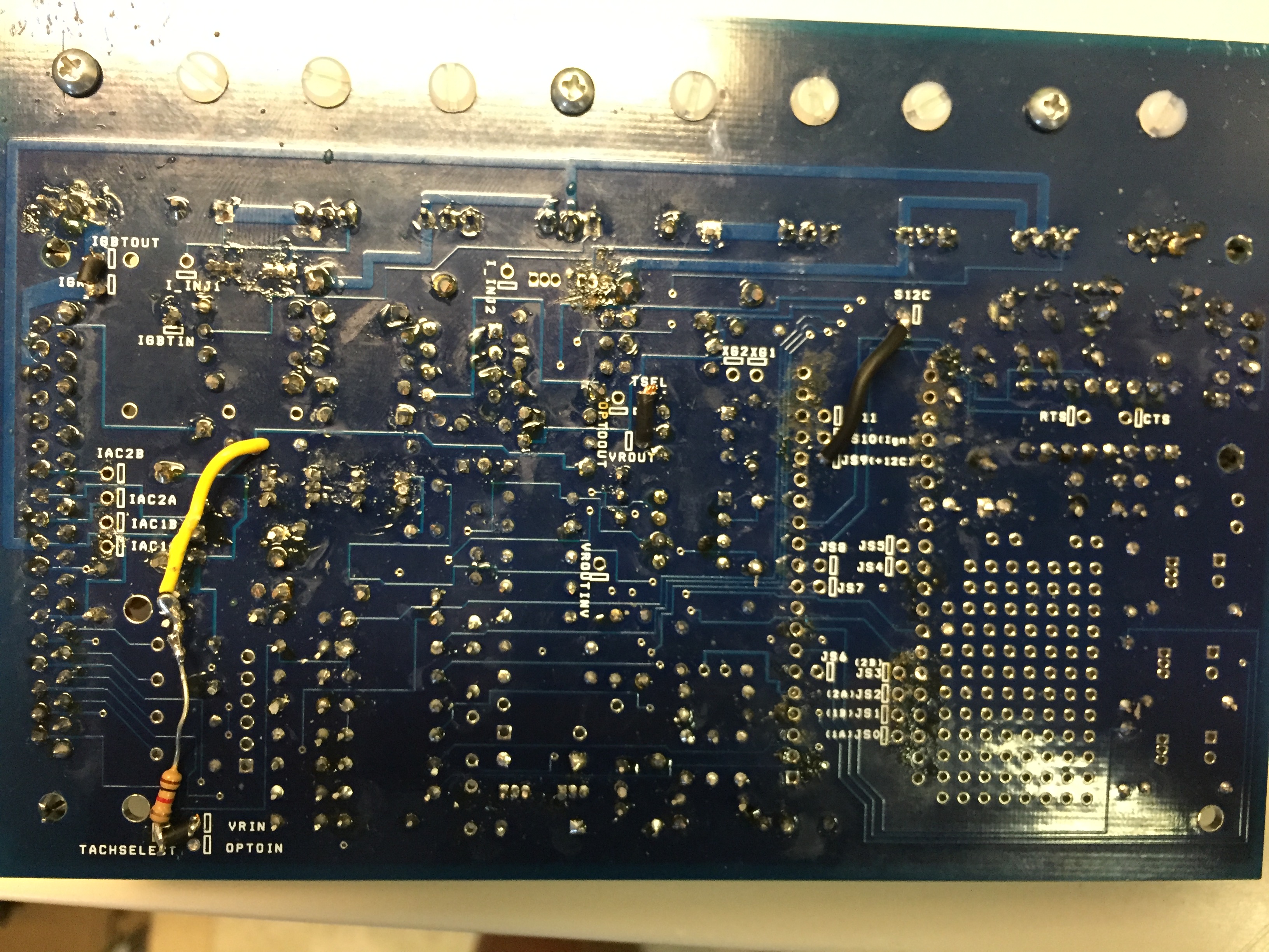
I would not put a "pull up "resistor like thats why theres a proto area. You can make things more tidy and if a connection was to break from bad joint or shock/vibration you have a short waiting to happen there. Use the proto area or atleast put it on a wire and heat shrink it.
Secondly I can see some of your mods but can you can list ALL your jumpers like this VROUT TO ABCXD , s12- js9 etc etc somethings in your pics is just not adding up maybe I have been on vacation too long. But me thinks you will not get RPM or Spark out. with MS theres more than 1 way to do the same thing.
I acutally changed it using the proto area after posting that picture. So now the resistors sit in there with leads to the appropriate holes.
Jumpers are as followed:
VR Sensor:
-VRIN to Tachselect
-TSEL to VROUT
Single High Output Coil
-IGBTOUT to IGN
-330r 1/4w res IGBTin and top of R26
Power
-S12c to JS9(+12c)
-
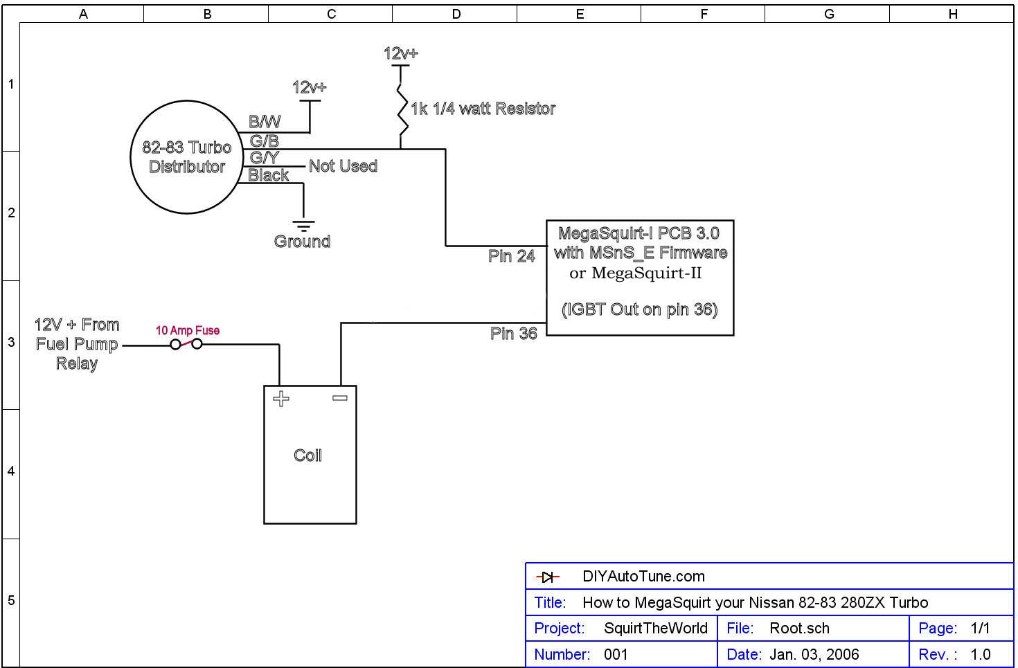
About to start up the car this weekend, just have to finishing wiring the distributor and the fuel pump and then its good to go.
May be a dumb question but wiring the distributor as per this diagram

----The 12v+(B/W): Guessing this is switched? I am using the relay board, so is there any slots I can plug it into or just find a random 12v switch wire?
-
On 3/28/2018 at 9:27 AM, ZHoob2004 said:
Measure the top and bottom pin. the resistance between these two should not change when the throttle blade is moved.
Essentially what you have with a tps is a resistor between the two outside pins and a movable center tap on that resistor (the center pin). The total resistance should not change, but how it is divided by that center tap will change as the wiper is moved along.
If you want to get (somewhat) technical, the TPS is acting as a voltage divider, and is dividing the 5v reference voltage to a smaller percentage of that, which the ECM reads and uses to calculate its position.
Extra side note not really related to the function: I wouldn't use that particular tps because the clip is broken, so the harness won't necessarily stay connected and could lead to some troubleshooting headaches for a pretty dumb reason.
How would I wire this to Megasquirt? The middle pin should be the signal wire, but how do I know which pin is the ground and the other power?
-
Just ran into a clearance problem that I do not see addressed in other forums. The way the steering is set up (outlined in red) there is no way that I can fit this hy35 holset in there.
Is the swap that I need manual rack and pinion to make this fit? Did not think this was going to be a problem with the swap ugh 😤
-
Test it with a screwdriver (poke around at it) and see if it is completely rusted out structurally. If you can mig weld , or weld in general it isn't a hard fix.
And if you dont want to patch fix it they also have complete floor boards and rails you can weld on.
-
6 hours ago, softopz said:
Depends on what megastim you have and the switch it's set at. Sometimes they don't read better to set up harness and plug in distributor.
Roger that. About to wire it up in the ZX and have chickenman help with the tune.
-
Delete please, got the part.
-
Just as an update I got the board firmware downloaded and hooked up to Tuner Studio. When using the megastim and moving the adjusters the corresponding gauges in the studio move, all besides the RPM (Well starts to then stops , says it needs to be calibrated).
However none of my LED's on the Board or the megastim light up, is this normal?
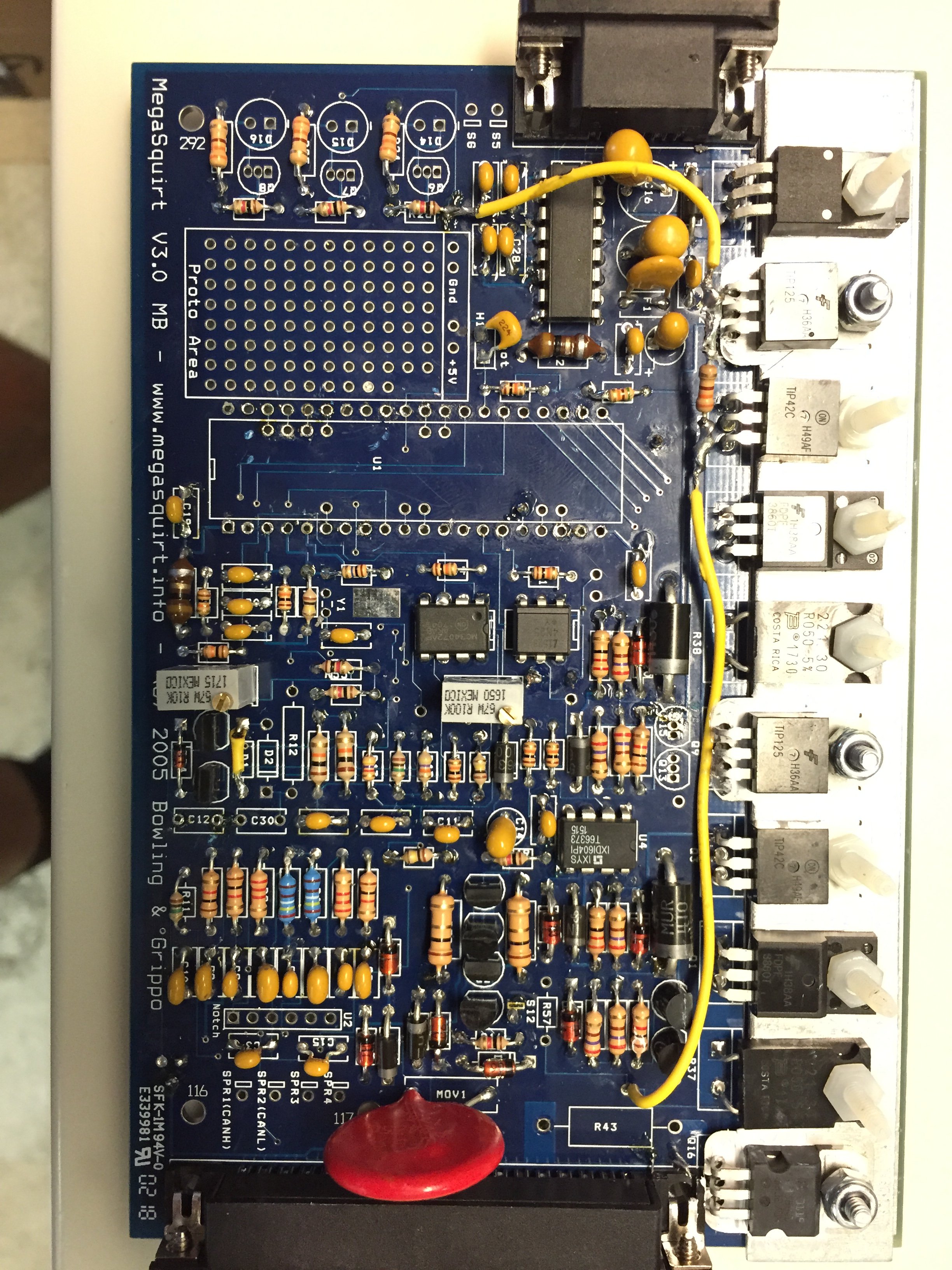
Also the board now has the motherboard along with R43 for High output coil.
-
Set up for single high output coil
82 turbo dizzy
no PWM idle
-
Did you ever get the HY35 exhaust flange welded up and downpipe made?
Currently looking to install the same setup in my vehicle.
-
23 hours ago, softopz said:
You should have stopped there and figured out the issue. Maybe you have a diode backwards. Make sure all banded ends are on the side noted on board. Also certain capacitors have to be installed correctly. I would look at your board and follow the steps one by one.
Powered it with the battery and all is well.
Checked the voltage according to the hardware manual and everything checks out.
All that is left is installing the transistor for the single coil setup.
Once I have the modifications done to the jumper wires I will upload a picture just to make sure that it is correct.
-
I was trying to do that step however I am not getting any power to PCB at all.
With the 9v in the stim, I am not even getting a reading at the + terminal of the stim when it is connected to MS2 board.
Ill just bench test it with a 12v battery and the 1amp fuse to the 28pin to see if the stim is the problem.
-
2 hours ago, cgsheen said:
Yes. Refer to page 76 of the MS2/V3.0 Hardware Manual. "Connect a 330R 1/4W Resistor between IGBTin and the top of R26." Be sure to follow all the steps in the section 5.3.1.1 on page 76.
For the "pull up" resistor (1K) needed when using the Nissan CAS, use the proto area on the version 3.0 board. It's very easy to fit IC's and discrete components in the holes. Fit your resistor in there and then use wires from S12 to one side of the resistor (that's your 12 volt source) and from the other side to TachSelect like the "Using DIYAutoTune.com's Nissan Optical Trigger Discs" .PDF says. Be sure to follow the other instructions in that document - there are other hardware mods to be made on an MS2/V3.0 board. Note that there are GROUND and +5V "holes" (connections) in the proto area - stay away from those for this connection.
I find it easy to insert the resistor and bend the leads over towards an adjoining hole. Cut the lead so it just barely goes to the adjoining hole. insert the stripped wire end in the adjoining hole (insulated wire is on the same side as the resistor, bare wire goes through the hole to meet up with the resistor lead on the opposite side of the board...). Lap the bare wire over the resistor lead and solder them together.
Okay ill make sure to do that once I get the resistor.
So I went to test the board and I plug the stim in with a 9v and noting happens. I am not even getting any power readings at the stim.
Isn't the stim not powered until connected to the board? If so even when connected I still do not have any power being drawn.I saw the stim manual on how to use it and it says I have to plug the other port into the computer and upload the firmware and studio, shouldn't I be able to just check for voltage without doing all of that? Only reason I ask is because my PC does not have a CD port on it, waiting for my laptop to arrive.
-
22 hours ago, softopz said:
Yes do NOT USE THE HALL INPUT anymore we really need a sticky on this and have DIYautotune update the installation article.
VR should be used for practically every MS input. ONLY hall/opto should be used for fuel ONLY setups running coil NEG for trigger input.
\ adjust your pots and measure top of R54 2.2-2.5v is good its all in the msextra manual here http://www.msextra.com/doc/pdf/MS2V30_Hardware-3.4.pdf
Also if your building your 3.0 board also use the MS extra pdf has the build up info with newer methods for building a board even though Megamanual works. IE c30
13) As long as you’re NOT using the coil –ve as the trigger input (Fuel only) find C30 and instead install it in H1/Boot (This adds smoothing to the battery voltage measurement and reduces the chance of noise getting injected into the CPU from the 12V line.)
Chickenman said it get the DIY wheel , Get a BIP and toss the HEI out. When setting up the 3.0 board do the pull up resistor inside the board instead of your wiring.
This is the good thing about MS and the bad theres so many ways of doing something and what works for one person may not work (depending on the hardware they have or ECU so many variables) PLUS with new methods of doing installs the old "stickys" are still the "go to" .
So my kit came with the BIP373 (Q16), it also came with BIP373 330o 1/4w, so i wont have to purchase the kit.
Do I use the BIP373 330 1/4w at all?
Instead of on the + wire from the VR sensor which leads to (DB37 pin24), where on the board would I solder the resistor?
For what its worth thanks for your help, along with chickenman and everyone else.
-
4 hours ago, Chickenman said:
Make your life simple. Buy the BIP373 coil driver from DIYAutoTuning. It's a whole $8.50. Forget about the HEI Module.
https://www.diyautotune.com/product/bosch-bip373-coil-driver-mod-kit/
Also, use ONLY the MSextra Hardware manual. That schematic is old news..... as is mostly everything in the Mega Manual. MSExtra Team has been doing the firmware development for the MS ECU's since about 2006. Anything marked " Mega Manual ", is from original B&G firmware developed before 2006... so its' only about 12 years old. A lot of improvements have been made since then.
You should also use the VR conditioner circuit instead of the Opt-In/Opt-Out circuitry. The VR conditioner gives a cleaner signal.
Softopz recommend this method ( VR conditioner ) . He custom builds MS2 ECU's and also custom harnesses for the L28 ET and just about anything you want. He's in the vendors forum.
Please note: I'm not a builder. I know a fair bit about MS builds, but I mainly do Remote Tuning. Once you get ready to run I can help you out with a Baseline set-up and Remote Tune for fisrt start-up. PM me for details.
Yeah Ill definitely contact you once I get it installed!
So I should get the BIP373 coil driver.
Should I also get the updated trigger wheel?
And to build the board I should set it up as below correct?
- You said to use VR Conditioner
- So I would need to set the board as a VR Sensor instead of the Opt-in/Opt-out
- a) Solder a link between VRIN and TACHSELECT
- b) Solder a wire between VrOUT and TSEL
-
With a small screwdriver, turn the pots, R52 and R56, about 12 turns anticlockwise (sometimes you may feel
a "click" when the end position is reached, they can't be damaged by turning too far.) This sets them up for most
VR sensors.
-
You only need one 7 pin (or 8 pin) HEI module to use a VR dizzy with the V2.2 megasquirt. I did this setup in a few chevy TPI engines. The basics are the same, the dizzy used a VR sensor. The 7 pin HEI picks up that signal and sends a trigger signal to the megasquirt for rpm/tach. The megasquirt controls the 7 pin module to fire the coil.
Look at this picture from the link that Matt gave for the 7 pin:
----Is this the setup I should be looking for with the distributor?
- However on the MS website they have this wiring diagram but there is no HEI is the wiring diagram even though it is for HEI.
- https://www.diyautotune.com/support/tech/install/nissan-datsun/megasquirt-your-280zx-turbo/
Wiring
The input side of things will be the same as mobythevan’s setup– it’s the output side of things that will change. Here’s a diagram of how to wire it all up if you’re laying out your own wiring harness. This diagram assumes you are splicing the connector from the OEM Nissan wiring – color designations are for the Nissan wiring harness, notthe MegaSquirt wiring.
- ----Sorry, I am just a little confused on the ignition aspect of the MS.
-
12 minutes ago, cgsheen said:
You should probably describe your setup - engine and spark configuration. Although to me at least, it sounds like you're using a single coil and already have an igniter (transistor ignition module, electronic ignition, blah, blah...). If that is the case, then the second bullet would be for you. Although for my MS2 v3.0 board builds I've been using the MS2/V3.0 Hardware Manual that Chickenman linked above and it doesn't have the same "step 22" that you're showing above.
Thanks chickenman for posting that link , I have been using http://www.megamanual.com/ms2/V3assemble.htm to assemble the board.
Currently I am using the stock coil and ignition module from a 81 l28e with a 83 turbo distributor.
-
Hello everyone, I am a little confused on step 22 of assembly guide of the Megasquirt board. Talking about the ignition control module with MS2
Isnt the ignition control the sensor on the Distributor?
I do not see any wiring diagrams for MS2 that show distributor, coil and igniter.
So I am not sure on which connection to make on the board since :- The ignition signal going to MegaSquirt-II to the DB37 pin 24, as usual. This is connected to pin 14 of the 40 pin socket (IRQ), and pin #1 of the MC9S12C32 processor.
-
The signal from MegaSquirt-II™ to the module comes out on:
-
Pin #17 of the 40 pin socket (labeled IGN), and is connected to the 5th hole of the JP1 header (pin 8 of the MC9S12C32). It MAY be connected to DB37 pin #30 with V2.2 main boards, if jumpered as recommended.
-
Pin #36 on the DB37 (JS10 jumpered to IGN) for V3.0 main boards if not using the high current ignition driver circuit (HEI/EDIS/etc.),
-
Pin #36 of the DB37 for V3.0 main boards (IGBTOUT jumpered to IGN) for V3.0 main boards if using the IGBT high current ignition driver circuit.
Note: If you are not using the high-current circuit to directly control a coil, you likely need to to add a pull-up resistor (which allows the signal to go both high and low, rather than floating and low).
-
Pin #17 of the 40 pin socket (labeled IGN), and is connected to the 5th hole of the JP1 header (pin 8 of the MC9S12C32). It MAY be connected to DB37 pin #30 with V2.2 main boards, if jumpered as recommended.
Am i suppose to do the second bullet since it is a V3 board not using high current?
-
7 hours ago, ZHoob2004 said:
Measure the top and bottom pin. the resistance between these two should not change when the throttle blade is moved.
Yup, the resistance does not change.
-
From the Megamanual
- To hook up your throttle position sensor (TPS), disconnect the TPS, and use a digital multi-meter. Switch it to measure resistance. The resistance between two of the connections will stay the same when the throttle is moved
- If you read a high resistance which gets lower as you open the throttle, then disconnected wire is the one which goes to ground, the other one which had the continuous resistance goes to the +5 Vref from the MegaSquirt® EFI Controller, and the remaining wire is the TPS sense wire
So I have a high resistance which gets lower as I open the throttle, however the other one does not have the continuous resistance. Instead it steadily increases when the throttle in opened.


Starter Issues
in Ignition and Electrical
Posted
So I checked my grounds again, and the bottom circled one was not connected 😐. However, after connecting it as in the picture, to the top of the starter, still no start. I am however just getting a single click sound coming from the starter. It does not even sound as if the gear is sticking out.
Also again verified not a battery problem since I jumped it directly from my truck battery.
Maybe not having the ground connected and trying to run the starter damaged it and I need a new one?