
240zdan
-
Posts
333 -
Joined
-
Last visited
-
Days Won
4
Content Type
Profiles
Forums
Blogs
Events
Gallery
Downloads
Store
Posts posted by 240zdan
-
-
The Hyme joints look cheap. On a part as critical as tc rods and front a arms, no thanks. I have TTT and it is QUALITY. Worth the extra $250.
Pretty sure CXracing makes their stuff in china.
-
wow. scary stuff. Perhaps you shoudl consider the TTT rear spindles and going to a more modern hub and wheel bearing. Expensive I know.
-
Im running #1 as my return from my surge tank. Works well. #3 is my vent and all other fittings are capped off except of course for the feed. Evap canister thing has to go.
Tee your vent into the fuel neck and run the other house outside the car.
Put a smoother 90 deg bend on the regulator, may help a bit.
-
The bore definetley needs to be turned on the lathe, but the drilling can be done on a drill press. Since the bore locates the hub to the rotor the drilled holes dont need to be extremeley precise, .005 is pretty easy to hold on a drill press though.
This is simple stuff, you should not be having as much issues as youre having with getting the job done. Like I said, I did mine in about 30 mins tops.
-
Anyone with a lathe and drill press can do it. I did mine in 10 mins.
The machinist screwed up, Im sorry to say it but you're rotors are junk. Turning the OD may create balance issues or may cause your rotor to snag on the caliper. Dont run them!
I have a set of caliper brackets I had lasercut but they are for GTR rotors. If you can source those then the brackets I have will work.
-
I ran 500whp, I turned down my power to a more reasonable 350-400 depending on my mood. Much happier with how the car behaves. 800hp is awd territory, good for scaring passengers and yourself but a bit pointless if you ask me. Its nice to know you have the power but honestley 300-400 is so much more enjoyable, the car will feel balanced and this allows you to run a smaller turbo for nice engine response.
-
Seam welding the car on a rotissire would be iffy n my book. You may warp some of the unibody, especially when the car is on its side. Most people stitch weld the chassis while its resting on the suspension points, staggering the welds to avoid warping. I stitch welded mine and would say its a waste of time. Most of your reinforcments should be tubular as the 240z is made of such thin metal. It may help, but probably not worth your time.
Main thing I would focus on are full length frame rails and a well built cage that ties into the suspension points. Let the tubes do the work. Reinforcing the TC rod area will give you piece of mind when slamming on the brakes. The front diff mount is always problematic, I tied mine into the rear subframe by building a cradle after tearing the welds off the original mounts.
Integrating your strut bar races into the cage would help alot. Running tubes from the cage to the engine bay would be killer.
If youre main question is can it be done without damaging the paint, I would say no. When I did my car I stripped it down to the shell. With all that cutting grinding and welding itll be hard not to scratch the paint. I would probably go as far as soda blasting the entire shell to have nice clean surfaces to weld to, then after all the mods are complete get everything painted nicely.
-
I'm not sure what you mean by the rear bars beside the shock towers. After we welded the cage in we removed the jacks and you could see that the chassis was much stiffer than before. By jacking up the rear passenger the entire side came up off the ground similar to my Z32. That never happened before. It also tells me it's a lot stiffer than before. Your opinion sounds more like speculation than fact but I'll take my experience instead.
The hoop is tilted back. We could have tilted it more but it was based on my seating position. Since I'm 5'5" not much room was needed.
The nail polish worked perfectly for me YMMV.
If you look underneath your car you will see that the rear floor doesnt really tie into the suspension of your car or any frame rails. In fact, you could theoretically cut out your entire rear floor and probably not notice much stiffness change at all. In addition, the rear support bars need to go to a place that can bear load. The rear shock towers are pretty much the only part of the car that can do that. The only load your rear floor bears is holding up your spare tire and groceries.
Speculation... Constructive criticism on forums is what this place is all about, I'm trying to help you.
Here are a few examples of what your rear support bars should look like.

This one takes things a step further and ties into the rear towers as well as the rear diff mount. Pretty slick
Here is Sung Kangs Greddy 240z, which has one of the worst cages I have seen. It looks like they welded the rear support bars to the floor, then realized it wouldnt do much to stiffen the suspension points. They then later added bars running to the shock towers which looks like an afterthought.
The only thing you are stiffening by tying into the rear floors is your bumper mounts. Your rear shock towers are still free to do whatever they please. Additionally its a safety concern. Like I said, you roll, the cage will punch through that thin sheetmetal floor. Also that main hoop needs to be tight!!! If you can fit 2 fingers between your main hoop and body you have some issues.
You can leave it, I'm not telling you to redo it. Its your car do whatever. But if I were to buy a car with a cage like that the first thing I'd be doing is cutting it out.
Nice work otherwise!
-
 1
1
-
-
Yes, this has been mentioned several times on the forums. Just bend the lines by hand to fit, its easy. Takes about 30 seconds to do.
-
Thats what I figured. Engine vibration is 99% of the time engine to body contact. Glad you got it fixed.
-
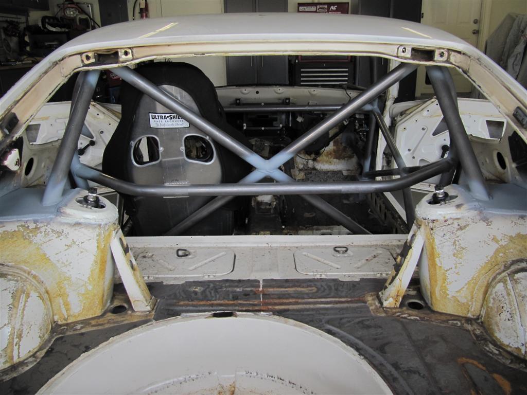
Nice work, but here are suggestions for your cage. The rear bars should go beside the shock tower, not the rear floor. The cage will just punch through the rear floor in the event of a rollover and you dont get the benefit of stiffening the chassis by tyng into a suspension point. If youre worried about your seatbelts, you will need to relocate them to the pillar. harnesses are another option.
The rear harness bar should be swept back, or main hoop tilted back. I don't know how tall you are but with the way it is now your knees will be touching the dash.
Also that main hoop should run much tighter to the body than that. The main hoop should be well above your head.
Also you need door bars. weld them to the floor by the rocker as far forward as possible. This will strengthen your front frame rails and tie the rear shock towers into the front rails. You can make it low if you dont want it intrusive. This will serve as a "secondary" frame rail which will help stiffen the front of the car significantly.
The nail polish suggestion is strange. It will probably look like shit. If it were me I'd paint the entire cage once its welded in with the same color as your powdercoat. That way it would be one uniform color, and the high wear areas woudlnt scratch as easily. The tricky part will be feathering the areas where you stripped the powder coat for welding, itll all show through.
Again, these are just suggestions, some people enjoy them others dont.
-
I've got .003 run-out in the lateral direction, measuring the face of the rotor. Radial run-out I believe refers to what you'd measure on the edge of the rotor. Basically, my rotor isn't centered on the hub properly. I had new rotors drilled, and the machinist didn't get it centered perfectly. I don't know if this is enough to cause some weight distribution, or balancing issues.
Measured like this:
It shouldn't matter if he didn't drill the holes accurately. The ID of the rotor should be machined to have a nice snug fit onto the hub, this is what centers it. He may have made that oversize or perhaps didnt dial the rotor in on the lathe before machining. If he didnt machine the id of the rotor then it has to be defective.
-
some updates.
ev14s going in next.
-
yeah i figured. Ive actually been emailing you (crxdan)
Did you have a tough time cutting off your megan lowers? any tips?
-
I got a few questions.
I currently have megans installed in my car, I am not happy with them as they are constantly blowing, and now the pillowballs are shot. I'd like to buy these coil overs. Do you know if the thread pitch is the same, since I already have strut tube adaptors welded in? I could machine the slot for the adjustment knob.
Can you sell the set without the adaptor tubes if the megans ones I made will work? Its honestley less work to slot mine for the adjustment knob vs using yours.
I would still need the camber plates.
Dan
-
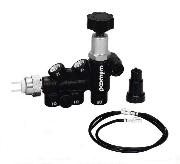
Another pic, I will be removing 10 and using the willwood in place of 8 to control bias. I will upgrade the rear brakes should I see fit.
I am certain that removing 10 and installing an adjustable valve, should it even need to be fully open, will improve the rear bias. It may still be forward biased, but it will be better.
I should have just asked what does the brake differential switch do and can I get rid of it, would have been much simpler.
-
As long as your brake set up is front biased, installing a pressure limiting device on the rear brake circuit would not do anything to improve the problem. Remember a PV can not raise the brake pressure - it limits it.
The so called brake upgrades for our Z cars (Toyota - Maxima, Toyota - 240SX etc.) typically result in a front to rear ratio of 60f/40r to 70f/30r.
The only way you can have a balanced brake system is to design it by the numbers taking into consideration factors such as master cylinder size, brake rotor diameter, number of pistons in the caliper, pad friction coefficient etc. If you do the brake torque calculations you will see what I mean.
Yes, you can replace the brake pressure differential valve (aka brake switch) with a three-way connector as shown in the attached picture. Do not consider "gutting" the switch as you would be connecting the front and rear brake circuits together.
Anything you change will have a domino effect because brake systems are engineered to work as a system.
There are many many threads here dealing with brake bias issues. You may want to study them before making any changes to your brake system.
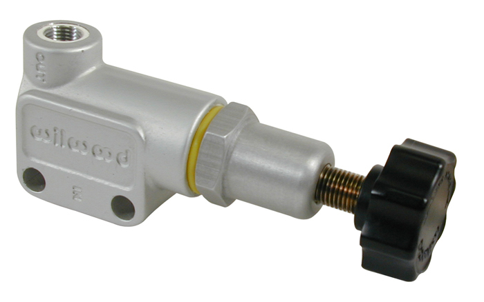
I am talking about removing the rear pressure restrictor under the car located in the rear. I have posted a pic, please take a look. As far as I know this is the stock proportioning valve, or restrictor.
Youve mentioned twice already that installing a proportioning valve cannot increase the pressure going to the rear brakes. I fully understand that, this is quite an obvious fact.
However, by removing the "restrictor" which I have posted a picture of, I effectively have full flow going to the rear brakes. An adjustable prop valve will let me dial it down should I need to or if I decide to upgrade the rear brakes in the future.
Again, I am fully aware that a prop valve can only decrease pressure. Please take a look at the photo I have posted.
Since removing the "brake"switch" has no negative effects, I will be buying the willwood 260-11179 to replace it entireley, which has a prop valve built in. I will then discard of the original prop valve under the car.
This was my question all along, the issue due to having too small rear brakes are a separate issue, and I will deal with that when the time comes.
I have gotten the information I needed from this topic.
-
Most likely your setup without a prop valve will still be front biased.
Im ok with that, I'll upgrade the rears down the road. But removing the stock prop valve and installing an adjustable one will help the situation, correct?
Is this the valve right here, below the three way tee?
My Main question here was whether or not I can remove the stock brake switch/splitter. From the looks of it I can.
-
Don't do anything. A PV would only be required if the rear brakes were more effective than the front brakes. That is "rear biased".
Almost all of the so called front - rear disk "upgrades" result in too much front brake bias. So installing a PV is counter intuitive.
The differential pressure safety switch turns on a red light on the dash if there is a leak in the front or rear brake circuits. All that happens is the piston inside moves to the low pressure side if there is a leak on that side and turns on the red light. That is it. Removing the differential pressure safety switch does not improve anything. Leave it alone.
If one front caliper is working better than the other caliper, then the caliper on the other side is defective. A number of things can cause this, usually a stuck piston or a leaking seal.
Appreciate your response. I am removing the rear pressure regulating valve (located in the rear of the car on early cars and in the engine bay on later). Are you saying that with this valve removed, and full flow going to the rears, my setup will be still front biased and the rears will not lock? Would be pretty crazy if that were true.
So since that brake switch just triggers a warning light, I will remove it and get the 260-11179 .
-
Did a bit of searching, couldn't find a definitive answer.
My setup is as follows:
GTR 4 piston fronts with GTR vented rotors
s13 rears with z31 non vented rotors.
Right now I am running the original prop valve in the rear, as well as the original "differential valve" in the engine bay.
I am looking for more rear bias.
Shoudl I retain the original "differntial valve in the engine bay and install an inline wilwood prop for the rear?
Or should I remove the OEM rear prop valve as well as the differential valve and install a willwood 260-11179 in its place?
What is the purpose of the original differntial valve in the engine bay? Right now I am noticing my front left caliper is much stronger than my front right, no leaks or seized pistons.
-
Experiencing a similar issue when i Run below 1/4 tank on hot days. Also running a walbro 255. I am going to try a Holley Billet EFI pump next. Alot of people have reported issues with the walbro 255 not coping with heat well. Thing gets noisey as hell when it happens too. I laugh when people say its normal Walbro whine when it happens. Not when your afrs lean out 1 full point, your fuel psi drops 15 psi, and you knock like mad....
-
Id be willing to place a bet that your bad vibration above 100mph is a drive shaft problem. Balance/run out will cause a DS to vibrate like mad at high speeds, minor runout in the adaptor plates or axles/wheels will not so much. I had a bad vibration and too found run out on one of my adaptor/stub axles. Fixed the problem vibration remained. It ended up being a DS that was out of balance, even though I it had made and balanced at a shop it still vibrated on the car for whatever reason. I hose clamped a large washer to the DS and moved it around until the vibration disappeared. You can also try rotating the DS on the pinion flange. Throw a indicator on the DS as well and see how much it runs out. I had .001" of DS runout on the car, and rotating it on the flange did not fix my vibration. The only thing that did was hose clamping a large washer to it, exact opposite end of where the shop installed a balance weight. A Lot of these shops cannot spin their shafts past 3000rpm, and this is when my vibration begins. With 4.11 gearing the problem only gets worse.
Now I am not saying this IS your problem, but Its something to look over with a fine tooth comb.
-
What would you be willing to pay for something like that?
-
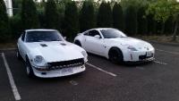
Those look good.
Heres some to avoid
Pretty much any style with the rears like that= BAD.


CX Racing suspension parts....
in Brakes, Wheels, Suspension and Chassis
Posted
Im sorry, but no.