wingwalker
-
Posts
64 -
Joined
-
Last visited
-
Days Won
3
Content Type
Profiles
Forums
Blogs
Events
Gallery
Downloads
Store
Everything posted by wingwalker
-
Grog and Twisted46, The alternator is 65 amps and I won't be running a huge stereo amp, so I believe 8 gauge will be okay. It think total it will be about a five-foot run. At the most, six. And I have been using the JTR book, but because this car had been hacked--not just wiriing, but on many other levels, the book is for me just a starting point. I think I have the correct wires for the HEI. At least I hope so. In a separate post today, I show some photos of us stuffing the engine onto its mounts. Feels good to have most of the wiring behind me, and the engine now bolted to the front mounts. (The transmission right now sits on a box. Fitting the rear mount will be next.)
-
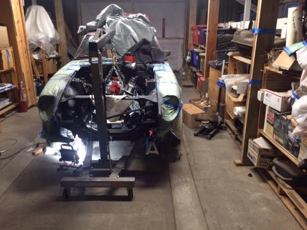
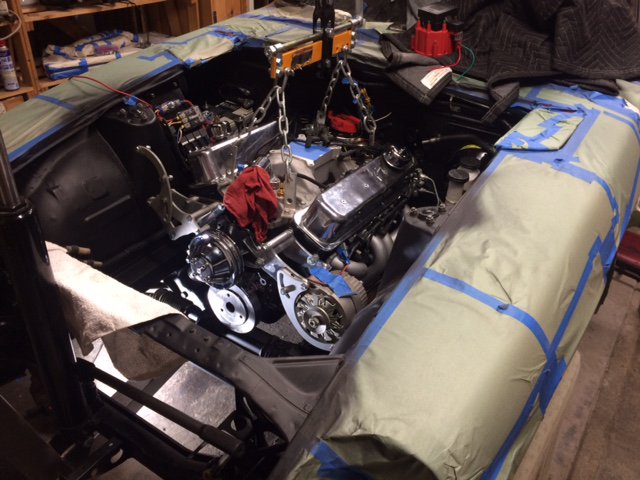
A young man comes to our little hobby farm about once a month to help with chores that my wife and I have fallen behind on or stuff that takes a lot of muscle-power (such as digging up burst sprinkler lines). He was here yesterday, I had finally finished wiring for the V8 (wiring hell, it was), and I realized with his help I might get the engine and transmission into the car. Finally. Our first attempt was a bust. My hoist could not get the engine close enough to the mounts. So, while he went about other chores, I lengthened the arm and removed the hood hinges and the torsion bars that were interfering with the hoist. And I pulled off the lower panel of the front valance, which was also holding back the hoist. Then we tried again. There was still a little shortfall, but with some mighty pushing, we got the engine in and bolts into the front mounts. Whew! I feel great, even though there is still a mountain of little chores before this old Z will once more be on the road. Here are a few photos.

-
Richard and JHM--thanks. I appreciate the input. As I mentioned, I ordered (from Jegs) a more robust 8-gauge wire kit, and when it arrives, I'll finish that bit. Right now I confused as hell about the wire to drive the tach. I have a blue wire separated and labeled for that, but I'm pretty sure it's wrong. I want to get this right, because I really don't want to cook the tach. -------------------- Okay, I just tested the blue wire to the tach resistor, and sure enough, they have continuity. So, I'll attach the blue wire to the negative on the HEI when the engine goes in and see what happens. The JTR book says to turn the brass adjustment on the back of the tach 45 degrees, but the text doesn't mention which way. I'll leave that step until after I have the car running, since this may have already been done (it previously had a SBC in it). Getting closer.
-
Richard and JHM--thanks. I appreciate the input. As I mentioned, I ordered (from Jegs) a more robust 8-gauge wire kit, and when it arrives, I'll finish that bit. Right now I confused as hell about the wire to drive the tach. I have a blue wire separated and labeled for that, but I'm pretty sure it's wrong. I want to get this right, because I really don't want to cook the tach.
-
Okay, without any feedback encouraging me to take the unconventional path, I will carry this feed-wire the long way around. But to avoid voltage drop, I have ordered 8-gauge to replace this 10-gauge wire. When It arrives, I'll route it around the front and be done with wiring hell. Finally.
-
Will this alternator bracket clear?
wingwalker replied to wingwalker's topic in Gen I & II Chevy V8 Tech Board
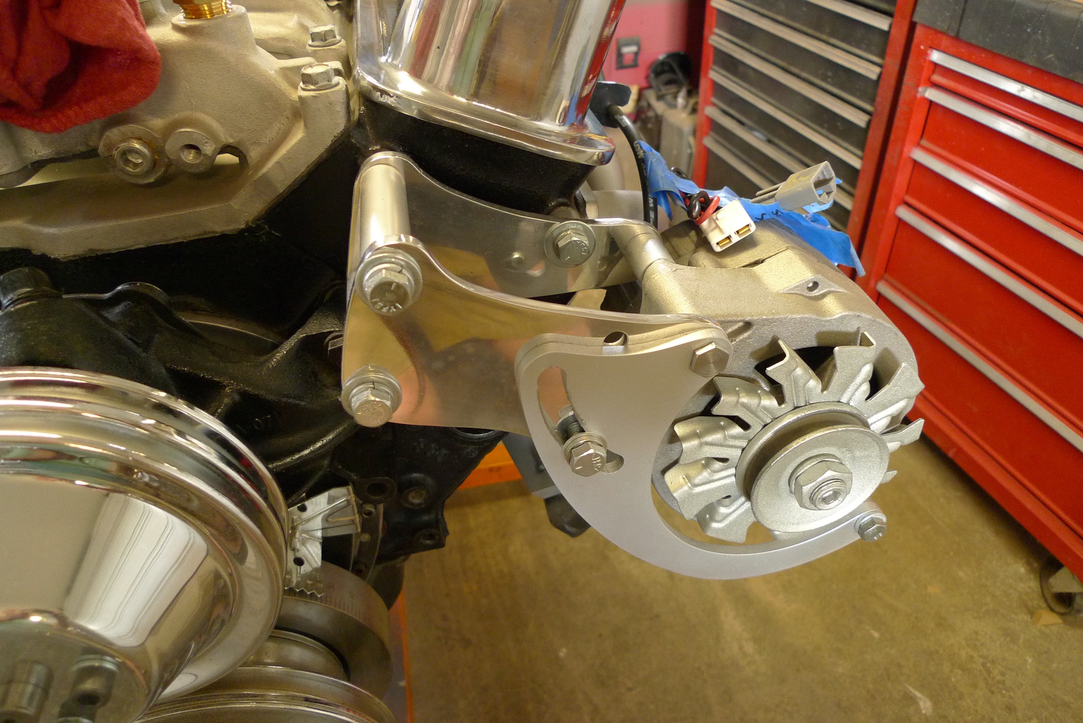
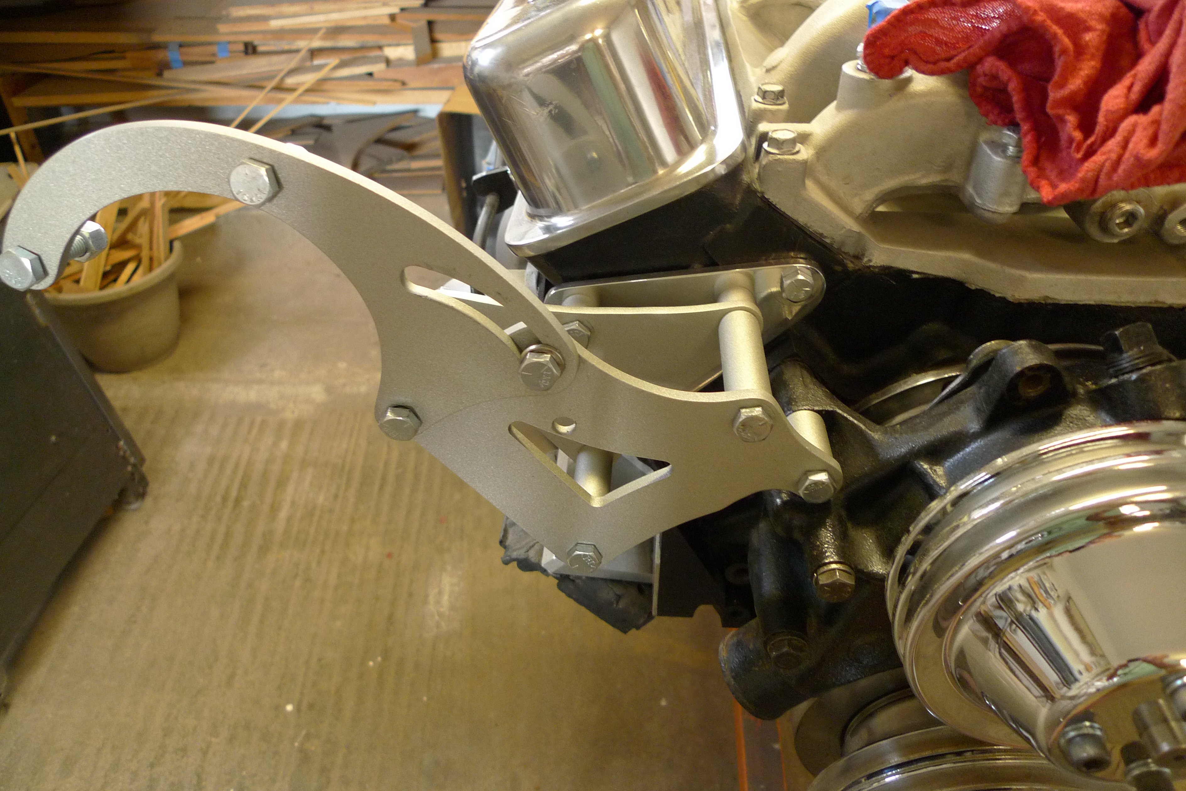
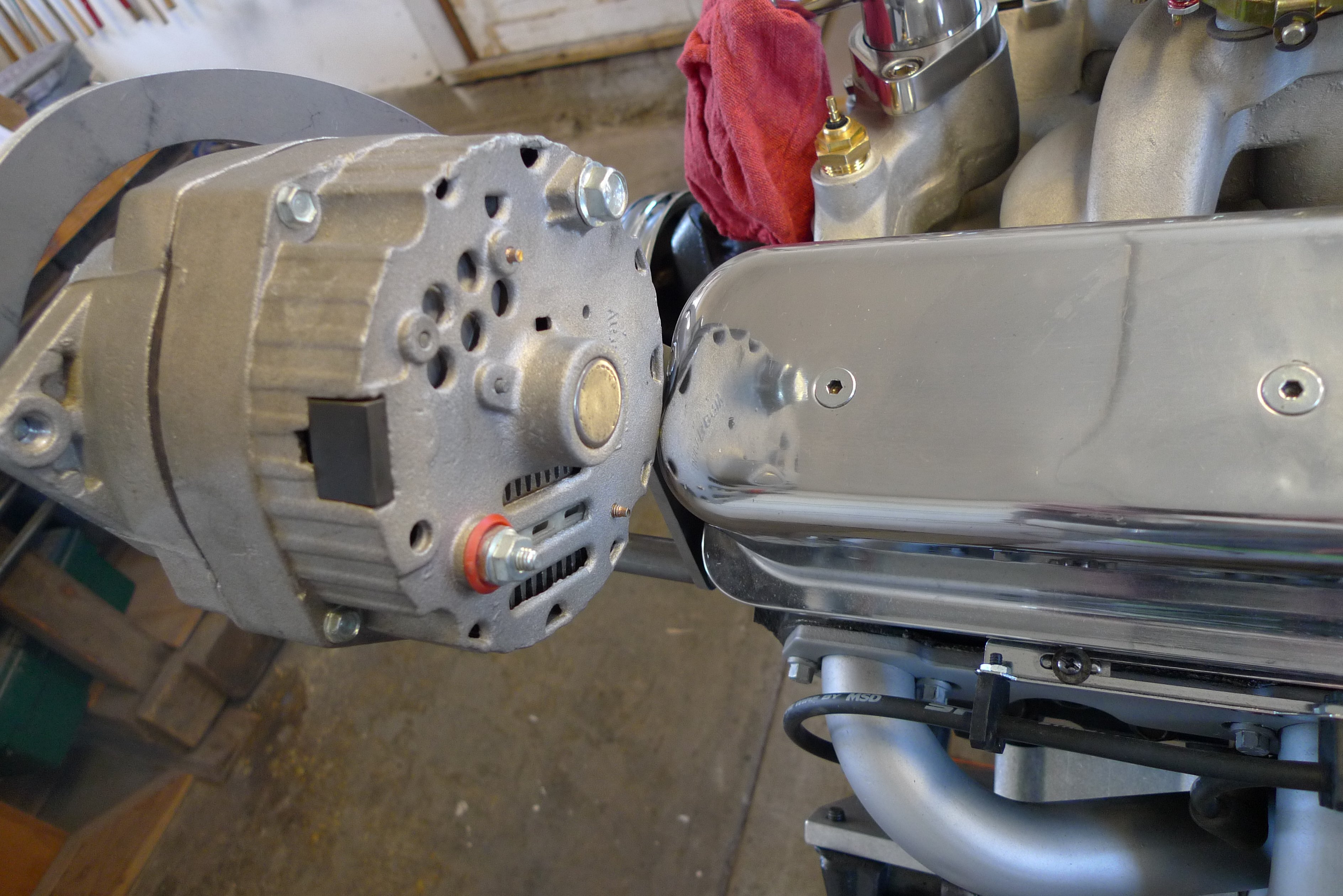
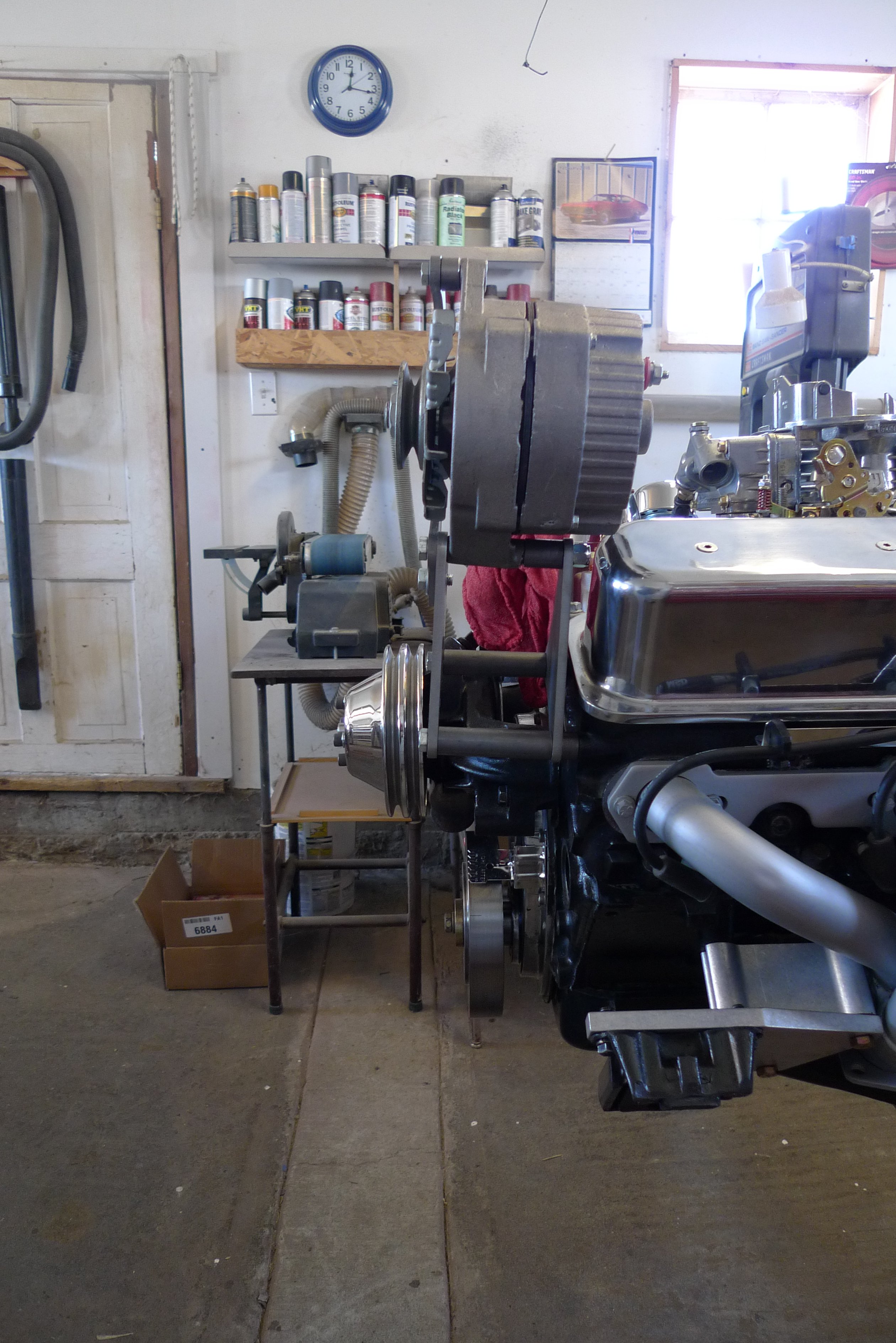
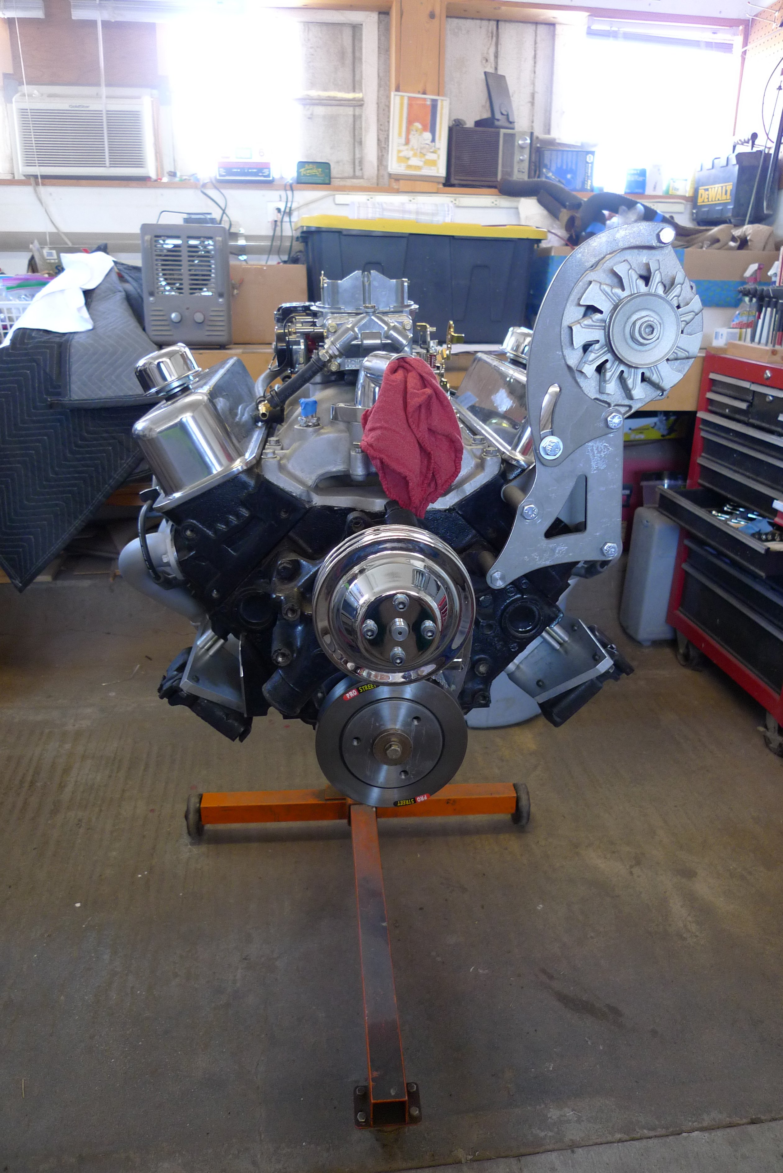
Here's the latest on the bracket saga. I tried three sets sourced by Summit Racing, and when the third set (made by Grove) was going to hit stuff, I bit the bullet and fabricated (actually, I modified the last set I got). The folks at Summit were super about the returns, but when the third set didn't work, I felt embarrassed. After all, three times! I used 1/4-inch aluminum plate to make the modified parts, and used as many parts as I could of Grove's stuff. The compressor is off now, but with both in place, I measured and measured, and I am now certain--well, almost certain--that these will work. Here are some photos.
-
I've been working on my 280 Z and will test-fit the engine (carbureted Vortec 350) once I am able to bundle up this bird's nest of wires. Because the guys at Vintage Air suggested I mount the compressor on the passenger side, I have my alternator on the driver side. And that means the wire feeding the alternator needs to run a long way. As you see in the photo, I was about to send it back to the firewall, across and then forward to feed the alt. But a few minutes ago I noticed that if I run it along the inner side of the cross-member, it is a pretty straight (and much shorter) shot. I have drawn in an arrow to the wire in question. Once that's decided, I can begin re-wrapping the harness. (By the way that relay closest to the firewall will be either for the fuel pump or for the electric fan--I haven't decided (and I'll take feedback on that issue, too).
-
Will this alternator bracket clear?
wingwalker replied to wingwalker's topic in Gen I & II Chevy V8 Tech Board
Capernix, jhm and Llave, Thank you all three for the responses. Jhm, I have rotated both brackets and, yes, it appears they can be modified so that both the compressor and alternator will be located lower. I'm thinking of dropping the engine into the bay and onto the mounts to determine just where I have room. Then I'll mark up the brackets for mods. After that, I'll take everything back where it is easier to work with the engine on a stand. Likely I'll find a few other issues to deal with while it is temporarily in there. Llave, a smaller alternator may also be part of the solution. But the size of the compressor, I think, is fixed. I plan on using a Vintage Air setup, and the system that will fit under the dash uses a Sanden 508. The 508 is a bit larger even than the 507 I have on hand, and that thing is larger than the alternator. Probably I should start worrying about it interfering with the headers. But I'll wait until the whole mess is in the engine bay. There is an answer, I know there is. I'll have to wait until the weather warms a bit before I hoist the engine. The part of my shop where the Z lives was at 14 degrees this morning and it hasn't warmed much since. I've been driven back into the house (where I should be working on my income tax filing--but, yuk, I'd rather brave the cold). -
Will this alternator bracket clear?
wingwalker replied to wingwalker's topic in Gen I & II Chevy V8 Tech Board
So, I sent the ICT brackets back, and Summit Racing's tech support guy suggested I talk with the Vintage Air guys (because I will be installing their system). The Vintage Air tech gave me parts numbers and I ordered them from Summit. They arrived in two shipments, with the alternator kit arriving Wednesday. I've bolted it in place, and once more, I think I am in trouble as far as fitting into the engine bay goes. It does indeed pull the brackets in close to the centerline of the engine, but wow, they put it up in the air. My measurements seem to show very severe conflict with the hood. And the compressor kit arrived yesterday, and clearly it will do the same. Once again the issues are: 1. Engine has Vortec heads with tall valve covers 2. I need the compressor on the passenger side, and alternator on driver side 3. It all needs to fit into the engine bay of a 280Z with a small-block (long water pump) engine sitting on JTR mounts. Please help me on this. This problem has to have been solved dozens of times. Photos of the latest bracket below: The issue of clearance with the valve cover can be cured with a mini alternator, but I suspect that the compressor will have a less-easily solved issue.
-
Will this alternator bracket clear?
wingwalker replied to wingwalker's topic in Gen I & II Chevy V8 Tech Board
Okay, as promised, here's the update. The ICT brackets put the alternator and compressor out too far. There is just over 31 inches between strut towers in the engine bay, and these brackets put the alternator to compressor distance out 32.5 inches. And with the JTR mounts, the engine is offset, which means on the passenger side, there is no hope of clearing. So, back to square one. I looked at the March options, and the alternator bracket will work. Nullbound's installation looks very nice. But I'd like to have the alternator on the driver side so that the compressor will be on the pass side, allowing a cleaner path for hoses. And I cannot find a March option that will do those things. Yikes, this has been done many times. There is an answer, but so far I'm lost. -
Will this alternator bracket clear?
wingwalker replied to wingwalker's topic in Gen I & II Chevy V8 Tech Board
Thanks, JHM. I'll post results after the brackets arrive and I then do a test fit of the engine in the car. Fingers crossed. -
Will this alternator bracket clear?
wingwalker replied to wingwalker's topic in Gen I & II Chevy V8 Tech Board
Thanks, JHM. These are ICT Billet brackets, and I went ahead and ordered them. I was assured by the vendor they would attach to the Vortec engine okay, so the fit in the engine bay will be the next unknown. For the pair, I'll save almost $50 if they work. I did find drawings with dimensions of both these and the Alan Grove brackets, and in comparison with the Grove equivalents, these appear to be within a half inch different in both side and height. So, we'll see. I'll post the results. I agree that an engine without all the stuff hanging from it will be easier to get in, but I want to test fit all the stuff while it is still accessible. That includes ensuring the pulley alignment is spot on and the belt sizes are determined. Just a lot easier with the engine at a nice working height. -
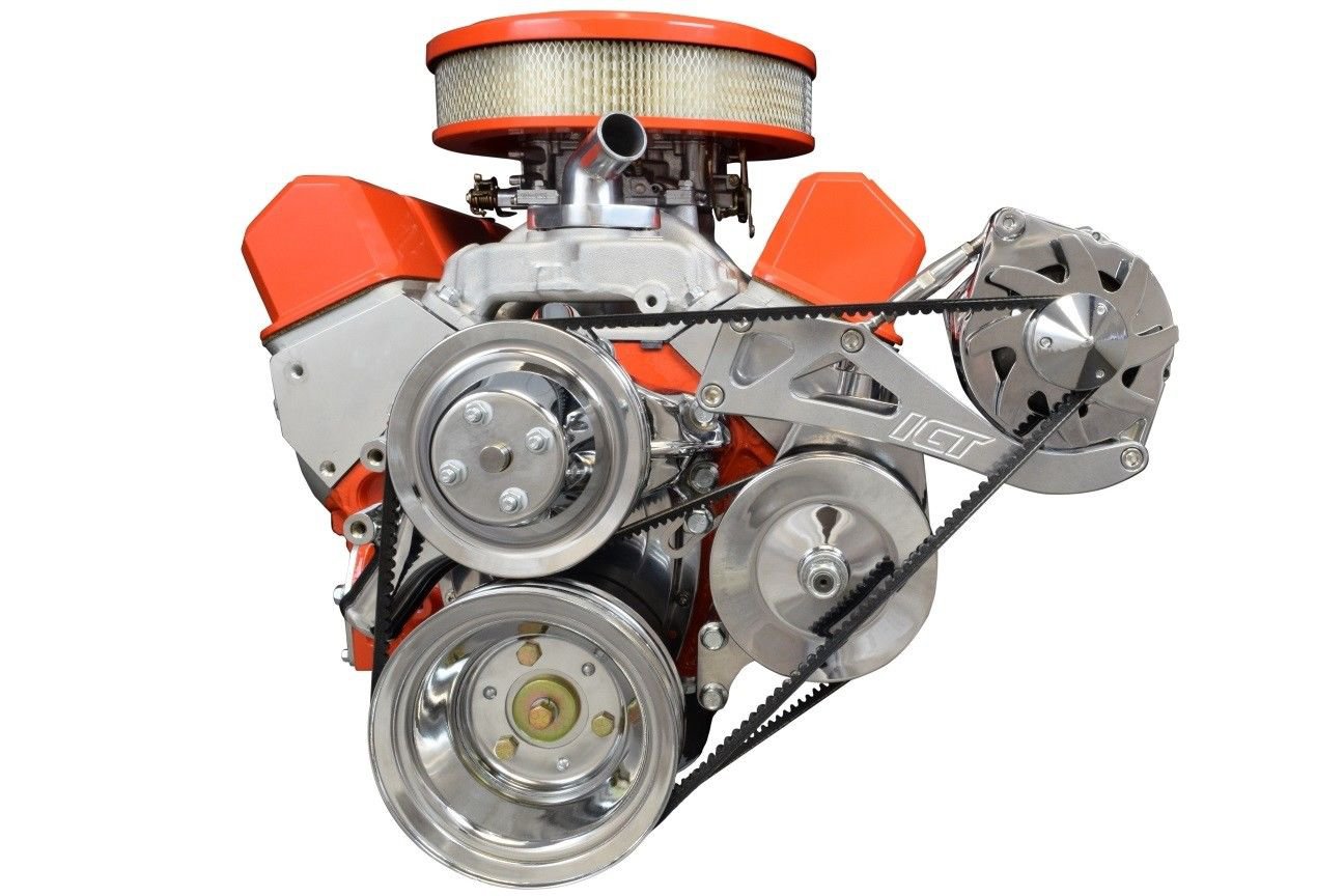
I am about to order this bracket and a similar one on the passenger side for an a/c compressor. But I worry they may not clear the sides of the engine bay. The engine is a Vortec 350. The car is a '77 280Z. If not these brackets, which? I have finally cut away and patched up the rust that grew under the batter tray, welded up excess holes in the engine compartment and have a JTR kit. Following the JTR book, I am now "dressing the engine," as the author puts it. So I want to attach stuff like these brackets and adjust belts before setting the engine in place.
-
Thanks for the info, Theczechone. So, what are my options? And does it even come out, or is it glued in place?
-
I have removed the non-working clock mechanism and replaced it with a digital outside air temperature gauge. Looks as if this will work fine, but I need to replace the current lens (which has a hole for the clock adjustment knob) with a blank lens. I assume the lenses on the other two small gauges are the same size and interchangeable. And I also assume they are not glued in and are easily pulled. I case you are wondering if I am abandoning an ability to keep track of time, I won't. As part of this build, I plan to put in a more modern radio, and most come with clocks.
-
My new 280Z project -- advice, please
wingwalker replied to wingwalker's topic in Gen I & II Chevy V8 Tech Board
Miles, this is so helpful. Right down to the part numbers. Since my tank is already out, I'll perform those mods to it. And replacing the sender while it's out is solid advice. Just a single fuel line to the engine will make it all less complex. And cleaner. Good tip on drilling the filler cap--I'd have gone nuts trouble-shooting that as the engine stalled a little while after starting it. Your engine bay looks awesome in the partial photo you posted, by the way. I searched to see if you had written up either of your builds and didn't find it. Did you do a write-up on that second build? Or the first? I'd love to see it. Or at least a full shot of the engine compartment. Thanks again for your help. -
My new 280Z project -- advice, please
wingwalker replied to wingwalker's topic in Gen I & II Chevy V8 Tech Board
After I said goodbye to an earlier project, an Alfa Romeo Spider (photo below) that is on its way to a new owner in Everett, WA, I decided the brave the heat and go into the un-airconditioned portion of my shop to tackle the engine compartment. I lasted a couple hours before I felt I was endangering my well-being. So I came in for, as my wife puts it, hydration. A beer would be wonderful, but I'm drilling out spot welds and that takes all my concentration (to keep the cutter from wandering all over the place). So the hydration comes from a mix of ice-tea and lemonade. I think it's called an Arnold Palmer. On our back deck--which is covered and enjoys a nice breeze--the thermometer reads 101. I'm guessing the air in my shop, which is still and warmed further by radiating heat from the metal roof (no ceiling or insulation), is maybe 15 or 20 degrees above that. Hot, hot, hot. Before I came inside I had cut out a number of extraneous brackets. I started in on the battery tray, which in several spots is tough to get the cutting tool to , so I when go back, that's the challenge I face. I am likely to be disappointed by serious rust under it, more than than what I see now. While working there, I was pleased to find that the previous owner brought the brake line for the right front up to the top of the frame rail. His bends were a bit tidier than the illustration in the JTR manual. Nice. I do have a question. I have searched this site and not found the full answer. There are three fuel lines coming from the rear of the car. I believe the smaller one is a vent line from the tank, and the other two feed fuel and then return what is not needed (as FI systems like to do). To clean up the engine compartment a little more, I am thinking of eliminating one of those lines. My engine will mount a carb--a new, still-in-the-box Holley 650 that came with the car, so I won't need the return. If that's a bad idea, please tell me. And could I vent the tank back in the rear and bring only a single line to the engine compartment? That would really tidy things up. Is that done? Here's the engine compartment and a shot of my Alfa (also purchased non-running). And while we are on this topic, why not bring the lines up on the firewall instead of leaving them along the frame rail near the heat of the header? Is that done?
-
My new 280Z project -- advice, please
wingwalker replied to wingwalker's topic in Gen I & II Chevy V8 Tech Board
Miles, again, thank you. This list is perfect. I'll test it against the 280Z wires and the schematic I have for it. This'll keep me out of trouble. -
My new 280Z project -- advice, please
wingwalker replied to wingwalker's topic in Gen I & II Chevy V8 Tech Board
Miles, great information. I'll order those from MSA along with the engine/transmission mounting hardware. My wife leaves town in a few hours, and I have a credit card, so I'll do it while she's gone. (Actually, she's supportive of my auto addiction. Less trouble that some of the other varieties.) I'm not ready to tackle the wiring mess yet, but when I do, I'll be asking about which wires can go away. I am okay reading schematics and wiring diagrams, but the one I have for this car is all on a single page--daunting. I go back and forth on this, and it may be a Painless kit, but if I don't go that route, I'll want to clean up the current mess, solder questionable spots and so forth, and then re-wrap it all neatly. Thanks again for the help. -
My new 280Z project -- advice, please
wingwalker replied to wingwalker's topic in Gen I & II Chevy V8 Tech Board
Miles, thank you once again. That sender in the manifold was there, but not hooked to anything in the wiring harness--or what passed as wiring in this Z. The question is, will this sender work with the stock Z gauge, or should I, as the JTR manual suggests, buy their adapter and also buy a Z sender? Cheaper, of course, to just use what is there, but will readings be accurate enough? The oil pressure sending unit teamed with a cut-off for the fuel pump is also detailed in the JTR book, and I'll order the parts necessary to accomplish that. This is all stuff I can get done in a cool room while awaiting temperatures that will allow me to tackle the many issues the chassis presents. However, next week my wife will be gone, so I may set the alarm lots earlier than she prefers and work in the main shop while it is still cool, then retreat when the temperatures soar mid-morning. -
My new 280Z project -- advice, please
wingwalker replied to wingwalker's topic in Gen I & II Chevy V8 Tech Board
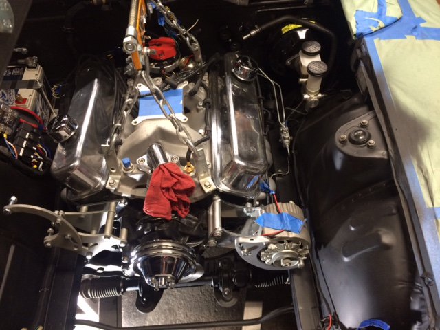
Still too hot to work in the part of my shop without air conditioning (which is where the Z resides), so I'm trying to get everything done on the engine and transmission to ensure they will be ready to drop in (after I have prepped the engine compartment). So, using the JTR book I see that need to adapt the Z temp sender and oil-pressure sender to the Chevy engine. And this raises a question that I have not been able to find on this site or the net. There appear to be two spots on the engine that can accommodate a temp sender. I shot a photo of the engine and labeled the spots as A and B. I suspect it is B, but since an adapter is involved, I want to make sure. Here's a photo of the engine.
-
My new 280Z project -- advice, please
wingwalker replied to wingwalker's topic in Gen I & II Chevy V8 Tech Board
Thanks for all the help, Miles. Very much appreciated. I just got a call that my torque converter has come in, and in a little while I will go downtown and pick it up. It's for the 2004R transmission I rebuilt this winter. So, once it is on the front of the tranny, I can mate the transmission to the engine and all will be ready for the car. Still lots to do before I put it in, but it feels like progress. Now I'll do that L31 search. -
My new 280Z project -- advice, please
wingwalker replied to wingwalker's topic in Gen I & II Chevy V8 Tech Board
Miles, Thank you for the random thoughts--which are actually not random at all, but very well aimed. They came in after I had sent the last reply. I'm leaning toward the MSA kit, especially now that you bring up the drive-shaft angle issue. Flexibility is a huge positive. Probably makes sense to buy the kit, drop the engine in and then deal with the typical fabrication problems as they come up. There isn't a huge rush, as I have to clean up and paint the engine compartment first. Which, as I think about it, reminds me what a mess the wiring was in. I can devote some time to cleaning up the stock harness, pulling any unused wires, and then warpping the remaining wires neatly. Or I might just buy a Painless Wiring 18- or 20-fuse kit and follow instructions. But first, there are a few rust issues . . . . -
My new 280Z project -- advice, please
wingwalker replied to wingwalker's topic in Gen I & II Chevy V8 Tech Board
Still no definitive answer on this question. I spoke with JTR, and the gent I spoke with is the brother of the man who wrote the book and did the engineering--who died a year ago. So, the brother had no firsthand knowledge of the damper issue. But he did note that they sell a spacer that will separate the front cross-member and the body by 3/8", which may solve the issue. I also spoke with a salesperson at MSA, and he had no information. He did say they had sold lots of kits over 20 years and never had the question. So, perhaps the cross-member spacer from JTR would solve the issue for either kit. I have to think about this some. Miles has been very helpful. Anyone else have information on dropping a L31 350 into a 280Z? Am I worrying about something that is not an issue. Or am I for sure going to have to buy a new damper, rent a puller, and then go through the mounting issues that may come with an after-market damper? -
My new 280Z project -- advice, please
wingwalker replied to wingwalker's topic in Gen I & II Chevy V8 Tech Board
Miles, the dampers in the link you sent are close, but won't work on my engine--which is the Vortec (L31) engine. Close, but no cigar--my engine is also 5.7L, but it was engineered for Vortec heads and roller tappets and I don't know what else. It was for sure a deviation from the small blocks to that point and was used mostly in trucks and Suburbans. Thank you so much for looking. I've scoured the Summit, Jegs and Speedway sites. GM doesn't offer one in less than 8-inch diameter (that I could find). Using Google I did find one last night from a supplier I had not heard of, but then it was going to take the better part of $500 to buy it and have it shipped. I am trying to do this on funds I received when I sold my Alfa Romeo last month--and they are limited. So I next call the folks at MSA and JTR to see if shimming might work.