
TheWeekendWagon
-
Posts
18 -
Joined
-
Last visited
Content Type
Profiles
Forums
Blogs
Events
Gallery
Downloads
Store
Posts posted by TheWeekendWagon
-
-
So this is a long story and I will answer any questions as I go but I am stuck. My car is running super rich and wont pass SMOG. I figured it would be time to go through and do the factory tune-up procedure (well most of it) in the FSM. Started with adjusting the valve lash. All but one needed some adjustment. Ran a lot smoother afterward, but didn't check AFRs as I was still waiting on my air/fuel gauge. Next I adjusted the cam timing. It was on setting 1 and was out of spec, moved it to setting 3 and it is better but still out of spec so I need a new timing chain. I then adjusted the ignition timing, it was off and I changed it to 10deg BTDC. Last thing I did was check the contacts on the TPS and that should be functioning properly.
My air/fuel gauge showed up today so I put it in to get some readings and see if anything I did helped. Hooked it up and it is rich at idle (about 12.9-13.0) and super rich at WOT (below 10). Stumbles at the top end of the RPM range, etc but otherwise idles and cruises part-throttle fine.
I have replaced the AFM with a rebuilt unit so I thought if everything else was in spec (except valve timing), I will start with the idle air mixture at the bypass screw in the AFM. No matter what I did with that screw, all the way in, all the way out, anything in between, the air/fuel ratio didn't change at idle. Still running really rich.
Went and checked the electrical at the ECU per the EFI section of the FSM. Everything checks out except the electrical connection for the air regulator but I don't see how this would be my problem.
Cold start valve is deleted, water temp sensor is new and has conductivity from ECU and good ground, injectors are all new and it runs great except at WOT so I don't think it's a single cylinder problem anyway.
The really confusing part is the lack of change in AFRs at idle no matter what I do with the bypass screw. What else can I check before cracking open the AFM and adjusting the spring tension?
-
The new relay worked!!! Well for most of the problems. Swapped out the relay and wired it up as I outlined in a previous post. Alternator wire gets power, alternator charges the battery, CHG light works, and the brake warning light is now only on if the e-brake is on and goes off once the e-brake is off. The only thing that still doesn't work is the tachometer which I will save for a different day. Thanks for your help NewZed!
-
7 minutes ago, NewZed said:
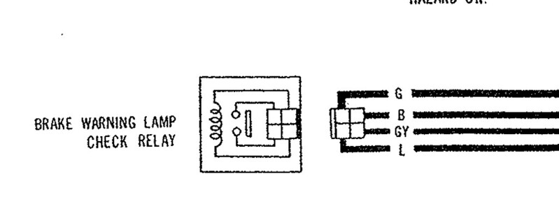
Seems right. 30 and 87 are the power for the device that is being controlled, B and GY. 85 and 86 are the circuit that does the controlling, G and L.
Yes, L would ground through the alternator. So that could be your missing L wire power, although there's supposed to be a second circuit, through the charge lamp. I'm not sure that diagram is right though, as you thought. Seems off. What bulb is being checked? The bulb check relay could be your whole problem.
Good luck.

The bulb being checked is the brake light on the speedo that is currently constantly lit. I am really hoping this relay is the whole problem, but I at least think it will fix the light in the dash. When it's not energized the light is not grounded out and it stays on. Its also tied to the e-brake handle which when depressed completes the connection to the relay to ground it out. When you pull the e-brake up, the connection is broken and the light comes on. Gonna try wiring in the new relay in the morning and if all goes well drive around without the passenger seat for a bit to make sure it doesn't catch on fire which looks like what happened to the old one.
-
Man some things I just have the hardest time grasping. Math and electrical systems are my top 2. I tried to do my own research on relays so I can figure out how to wire in a new one but I have no confidence in my understanding. Sorry for the simple questions.
The way I understand a relay works is the coil is energized by a triggered power source on one end and ground on the other. Why then does the wiring diagram look like this?
It looks to me as though the coil is not directly grounded. The green wire (G) comes from the fuse panel so that's triggered power in by the ignition as the switch. The blue wire (L) is the one that goes to the alternator...the wire that isn't getting power. Does it ground through the alternator? The green/yellow wire (GY) runs through the e-brake switch, the light on the dash, and the fluid level switch. The black (B) goes to ground.
Am I understanding this correctly? So when the ignition turns on power is sent through the coil to the alternator where it eventually grounds out activating the coil in the relay. The coil in the relay is used to trigger grounding out the GY wire. So, if the coil is fried in the relay power isn't going through to the alternator and it isn't being grounded so there's no triggering the relay. That doesn't ground out the GY circuit and the light on the dash stays on. Bob's your uncle that's my problem!? Or am I way off? haha.
If I am correct then I could wire in a standard relay as follows...
86 - G
85 - L
30 - GY
87 - B
I just want to run it by you all before I catch something on fire.
-
Broke open the Brake Warning Check Lamp Relay under the passenger seat. I don't think it's supposed to look like this! Fingers crossed a new relay solves at least the charging issue. It's gotta fix something!
-
58 minutes ago, NewZed said:
You're not really grasping the basics of electrical circuit troubleshooting.
I'll be the first to admit that!
58 minutes ago, NewZed said:There is a path that the electricity follows. Use your meter and follow that path until you find that point that has no electricity. You don't have to hope or guess. It will be yes-yes-yes--no as you check the critical spots on the path. You probably left a connector unplugged, or mixed two up. The shape of the connector matches what the diagram shows. The tachometer diagram shows the position of the connector in the relay panel. Poke-read-poke-read-poke-read....
Understood. I just get a little confused on the path after it starts splitting up and going through the gauges and relays. I am likely just overthinking it and second guessing myself.
58 minutes ago, NewZed said:Edit - the case of the alternator needs a good ground. It should ground through the mounting points but there is also a dedicated ground terminal, the "E" post. Check the ground. With your meter.
Alternator ground is good. Thanks for all your help by the way! I appreciate your patience.
-
I did check voltage into and out of that fuse and they are both good. Ignition relay is also good. Everything worked fine before I stripped out the entire interior, wiring harness and all, to clean and rebuild it and the problems started immediately after it was put back together so it has to be something I messed up. Something missing a ground or hooked up wrong, or maybe I dropped a relay and broke it or something I am not sure but I feel it would be too much of a coincidence for something to just go bad naturally while the work was being done. That's why I removed the dash because one of the changes I made from factory was swapping all the bulbs to LED, including the CHG light. So I was hoping that was the issue. Plus pulling the dash isn't that hard and I wanted to put an eyeball on everything back there for peace of mind. Changed the CHG bulb back to stock, verified it had good contact. Wiring all looked great, everything appeared to be hooked up properly, no loose connections, etc. I don't think it was anything in the engine bay as none of that was touched and I am more confused by the wiring diagrams than anything else so I am attacking components first. I am REALLY hoping its the Brake Warning Lamp Relay that's under the passenger seat. That was removed and re-installed during the interior job. I don't know if it makes much sense as I am not proficient in reading wiring diagrams but I know that I can at least trace the wires from this relay to each thing that isn't working properly.
-
So I finally got back around to trying to tackle this issue again and unfortunately, no luck.
I took the entire dash out, took out the LED bulb I had swapped into the CHG light. Replaced it with a standard bulb. Ensure the wiring had good contact to/from the bulb and un-loomed and inspected the entire dash wiring harness. Everything on the dash end looks fine visually. Car still isn't charging, the CHG light still doesn't come on, the tach still doesn't work, and the e-brake light is still permanently lit.
So if we can eliminate any issues before the fuse panel and eliminate any issues behind the dash...what's next?
Next on my hit list I think is the Brake Warning Check Relay. Anyone know where on the car that is located? Is that the relay under the passenger seat?
-
2 hours ago, NewZed said:
I was going to mention what Sam280Z said about the Charge light. But the diagram shows a parallel circuit with the check relay so that wouldn't be a problem IF the diagram is correct. Current through the check relay solenoid would supply the L circuit and the bulb circuit would not be necessary.
Now that you've mentioned all of the other problems, it seems more likely that it could be the cause and the diagram is not correct.
Good luck. At least you know that it's power to the L wire that is the problem.
Yeah it's a starting point at least!
Side note. Replaced both of the fuses and as expected no change. They were good to begin with. The rest will have to wait a week until I get home and have some time to take the dash out and get to that volt gauge.
-
16 hours ago, NewZed said:
According to one diagram that I have that is the L wire, for Lamp. It supplies power to the alternator windings. That would explain your problem. Now you just have to find out why it doesn't have power.
Nissan made things complicated in 1978 with lots of extra relays and gizmos. I think that the best you can do is to follow that wire back. Looks like it gets power through a"check relay" (maybe your e-brake warning light) and also the Charge lamp. The Charge lamp in the meter should light up when the key is on.
The colors aren't right in my copy of the 78 FSM but it shows the various connectors. Maybe you just lost a connection.
Edit - looks like they only mislabeled the color, WB, right at the plug. It's back to "L" (blue) farther down the circuit. It does indicate a splice to a yellow wire along the way. Nissan used a crimp on to exposed wire to create branches. Likely a stressed point, susceptible to bending and fatigue.
Hmm, I have been using a diagram for the whole car which shows things slightly different than that one. Question about the Bulb Check Relay...if that wasn't getting power from the fuse block, would that trigger the brake warning light on the speedometer? If so then the fuse makes the most sense as the cause of the problem, however visually the fuse looks fine. Going to try and change it anyway just to rule it out.
34 minutes ago, Sam280Z said:Is the charge warning light coming on in the voltmeter gauge? the alternator will not charge if that bulb is burnt-out.
That's a likely culprit too as I had that gauge removed to change the main light to LED. I don't remember if I switched the charge light to LED or if it was a different size bulb. Unfortunately I don't think I will have time to remove the dash to get to it before I leave town for a week so that will have to wait if the fuse thing doesn't work which I kind of don't think it will based on the info below.
SIDE NOTE:
The whole car wiring diagram I have been staring at for hours shows the charging system wired a little differently than the diagram posted in this thread. The broken down diagram shows the whole circuit running off of one fuse while the whole car diagram shows it running off of two fuses (3rd + 4th from top on the Left). It shows the "G" wire coming off of the 3rd fuse down whereas the broken down diagram shows it coming off of the 4th. The whole car also shows the many other things that are powered by those two fuses, most of which work which kind of debunks the fuse theory. BUT the interesting thing is that all of my current problem areas with the car, all problems that started at the same time, can be traced back to those two fuses: Alternator not charging, e-brake warning light on speedo constantly lit, tach not reading RPMs, charge light on volt gauge doesn't work.
-
43 minutes ago, NewZed said:
Get a voltmeter and measure voltage at the plug to the back of the alternator. The T plug. They should both show 12 volts with the key on. Also make sure that plug is making good contact with the pins in the alternator. I had a plug that was loose and was not making contact. Had to recrimp it with a pair if pliers.
Make sure that the charge wire to the lug on the starter is intact. It's the white wire that starts at the B terminal on the back of the alternator. And check your fusible links.
Thanks for the quick reply! Fusible links and starter connection are in-tact and good. The White/Red wire to the T-Plug shows 12V BUT the Light Blue wire on the T-Plug shows nothing so maybe that's the problem? The contact is great and I even put a new terminal end on it to make sure there was zero corrosion at the connection point to the alternator.
From the wiring diagram I can see that Light Blue wire is also connected to the following...
Fuel Pump Control Relay - Fuel pump and fuel delivery have no issues.
Voltage Gauge - Seems to be working fine although I am not sure the charge light works as it never came on as the battery drained.
Brake Warning Lamp Check Relay - If this is the light on the speedo that lets you know the e-brake is up, that is permanently on even when the e-brake is down.
The brake warning lamp connection may make some sense and leads me to believe I should probably list other issues with the car as maybe there's a connection there that makes sense to someone more educated than I. So I just did a big interior overhaul (carpet, seats, etc.). One of those items I did was change the bulbs in the gauges to LED. They all work but a few new problems, including this one, have arisen since the interior overhaul. Aside from the charging issue and the e-brake warning lamp constantly staying lit the tachometer also doesn't read RPM. The turn signal lamps and such work on the tach, it's just not getting a signal for RPM. I haven't dove into this issue yet aside from double checking my connections at the tach which are good.
So what is the purpose of the Light Blue wire coming from the alternator? Does it make sense that there is no power at the alternator but there is power getting to the e-brake warning light and the fuel pump control relay?
-
I'm having some charging issues with my '78 280Z and there's so much information on the internet it's kind of overwhelming so I am hoping being able to actually talk with you guys can help! Was letting the car warm up the other day and then it started running rough and I noticed the volt meter needle was down around 8v. Assumed it was the old alternator that has been on there for who knows how long. Bought and installed new alternator, re-charged battery, and just went to test it again and same thing. The voltage slowly drops as the car is running and doesn't recover on its own. So here's some bullet points.
- Car wont hold charge.
- Same problem with old and new alternators
- Battery will take a charge, but it's older too.
- Wire connections at alternator appear to be okay.
- Belt seems newer, good tension, no visible issues.
EDIT: FIXED!!! The culprit, a bad Brake Warning Lamp Relay, located under the passenger seat. Replaced with a standard 4-pin relay and wired it up as follows...
86 - Green
85 - Light Blue
30 - Green w/Yellow Stripe
87 - Black
The alternator now charges the battery, the CHG light works again, and the brake warning light now works properly. The tachometer still does not work but that is a separate and unrelated problem. Hope this can help someone in the future!
-
Oh man, those look identical. Unfortunately I ended up grossly over-paying for a new one from JDM-Car-Parts.com. Awesome that they have new ones but yeah I am sure I could have snagged a much cheaper junkyard pull from one of those. Great info though!
-
52 minutes ago, wal280z said:
@jhm I'll give the OP two weeks to respond - if you want them to re-sell, come and get em!
wal280z - Thanks man! I did end up getting some lenses from another member though so feel free to give them up to whomever needs them.
-
5 hours ago, nzarano said:
random question but does anyone know if this could find its way onto a 240z with a vintage air kit? currently just have my idle higher in the summer then lower it in winter but would love a better solution to this...
It is vacuum operated and triggered when the A/C compressor is turned on. I am not sure how the Vintage Air system works but I would assume it's all electric? I suppose you could get an electric vacuum pump that is triggered by the power wire for the compressor if that's the case.
-
Looking for the rubber grommet that goes around the heater hoses on the firewall. Anything from a '75-'78 Z should fit. I don't need the metal cover just the rubber piece as mine crumbled into pieces when I took it off.
-
Tried to restore my speedo/tach plastic lenses on my '78 280Z with a headlight restoration kit and just made them worse haha. Looking for new ones, preferably nice and clear without a bunch of scratches. I don't need the whole gauge just the clear plastic lenses. They are the same for the speedo and tach so if you have two tachs or two speedos lying around that works too. And although the gauges themselves are slightly different I believe any model year has the same plastic lens. For price/shipping purposes I prefer to buy just the lenses if possible but if the price is right I don't mind buying the whole gauge. They don't have to work.
-
1 hour ago, LanceVance said:
I've got 1 or 2 in the spare parts bins. Shoot me a PM with your address and I'll get you shipped price.
PM sent!
-
Looking for one to complete my factory A/C rebuild on my '78. It's one of the ugly things that bolts to the intake manifold...
-
13 hours ago, cgsheen said:
No (or not necessarily...).
A relay is just an electrically operated switch. It's almost always activated by another switch (switch working a switch - weird huh?). Many of the switches in a Z are "switching" (breaking) the ground wire. Thats the case here. So, the relay coil is powered by the wire from the fuse panel (which is activated by the ACC (accessories) circuit I believe (it's not "hot" continually)) BUT, it's not active (the electromagnet doesn't "work") until it has a ground applied (has a path to ground). The ground comes from the blower switch and passes through all the other control switches in the A/C circuitry (microswitch, thermostat switch, etc.) If any of these switches in line are not "made" (closed), the relay coil is inactive (no path to ground) and it's switch is "open" which simply means no voltage is being passed to the compressor clutch magnet.
The relay is a way to control the switching of the compressor ON/OFF with lower amperage wiring and switches while the relay switch provides a higher amperage wiring path to the compressor.
The relay itself is VERY simple, the multitude of additional switches and safeties and controls in the A/C circuitry make understanding the circuit more difficult. You probably got lost at the blower switch...
(The ground path is: Earth (shown in diagram above as an attachment to the body of the Ignition Relay) B -> Blower Switch -> LW -> LY MicroSwitch -> Y Thermostat Switch -> BG to Connector -> YR Pressure Switch -> Y to Relay. (If you look closely at the Blower Switch, it shows that B -> LW is closed in all fan speed positions and open when in the OFF position.)
OK, all the wire color changes don't help either...
The Pressure Switch in these cars is a "high pressure cutout". That switch should ordinarily be closed unless the high pressure side (liquid line) of the refrigeration tubing is overly high pressure. That doesn't happen normally if the A/C refrigerant charge is correct, but it's a "safety" that "shuts off" the compressor in an over-pressure situation. It does that by removing the ground connection to the A/C Relay. It resets itself when the pressure drops.
Awesome, thanks! It's all making sense now!
-
10 hours ago, cgsheen said:
The two LY's are +12v power from the fuse block - one is power to the relay switch and one is power to the relay coil, the L is power out of the relay switch (the opposite side of the switch to your LY) to the compressor clutch magnet, Y is obviously the ground side of the relay coil (again, opposite side of the coil than your 2nd LY). That's how you wire up your new relay...
Thanks! I must admit I still don't fully understand how that is the conclusion but I will take your word for it! I would like to learn more about this part of things as it is admittedly one of my weakest areas of automotive knowledge so if you don't mind a few more questions I would appreciate the lesson!
My confusion lies with both LY 12V power lines being constantly fed power from the fuse box. if the power to the coil is constant wouldn't that mean the relay is always triggered? In it's normal state shouldn't it not be getting power until the switch sends power to it triggering the relay? Clearly I am not understanding something here as I don't think Datsun would have some sort of weird voodoo relay, but I would like to understand. From what I gather you have the power and ground to the coil in the relay. You hit the switch, power goes to the coil and creates the magnetic field that makes the connection between the constant power source and the thing you're trying to turn on. In this particular case is the F.I.C.D. or the Pressure Switch the key to how this all works? Does the coil not get ground unless the pressure switch connection is made?
-
12 minutes ago, calZ said:
Four pin relays have two grounds and two positive, not 3 positive and 1 ground. I could guess at what the wires are based only on that, but you really should be able to figure it out based on the wiring diagram. Trace LY as far as you can and see if it runs to ground somewhere.
Well you would think I would be able to figure it out, but I am either reading the wiring diagram wrong or not understanding how that particular factory relay works.
From what I can tell LY originates at the fuse block so I would think it was power. Here's the wiring diagram for the A/C circuit...
-
Also in somewhat related news, the only other part I am missing is the fast idle actuator that bolts to the intake manifold if anyone has one they want to sell!
-
CLIFFS NOTES:
Has anyone replaced the factory A/C relay with an aftermarket relay? If so, what specs did you get and how did you wire it up?
LONG VERSION:
Almost done returning my 280Z to functioning factory A/C after a previous owner's questionable retrofit/repair job. One of the last pieces I am missing is the factory A/C relay. It is missing completely and it is super hard to find without spending $80+.
Question #1 - Can it be replaced with a standard off-the-shelf relay? I would assume so, but I am not sure the specs on the factory one.
Question #2 - How would it be wired? It's not super straight forward on the factory wiring diagram side. I have stared at it for hours and I can't confidently figure it out.
There are 4 wires from the factory, 2x LY, L, and Y
Usually on a relay you have constant power, power from the switch, power to the component you're trying to turn on, and ground. I am no wiring expert but I cannot for the life of me figure out how the factory wiring diagram gets all those things to the relay.
The LY wires appear to be the power wires from the switch. It can be traced from the fuse box to the blower motor and a/c resistor (switch), then it runs to the relay where it splits into 3. Two of the LY wires go to the relay, the other goes to the F.I.C.D. Why are there two LY wires going to the relay when the originate from the same main wire?
The L wire, this one is pretty clearly the power to the compressor and it also branches off to the F.I.C.D. The A/C is switched on, the relay triggers and sends power to the compressor and F.I.C.D. Got it. That's the only easy one.
The Y wire goes from the relay to the Pressure Switch.
Which one is ground? Which one is 12V constant? It's driving me crazy!
Thanks in advance for any help!


Need tuning help/diagnosis '78 280Z Factory EFI
in S30 Series - 240z, 260z, 280z
Posted
ZCarSource.com
I just want to make sure that everything else is as it should be before I start messing with it. I am more puzzled with the fact that the bypass screw doesn't seem to do anything for my AFRs at idle.