

Jethoncho
-
Posts
95 -
Joined
-
Last visited
Content Type
Profiles
Forums
Blogs
Events
Gallery
Downloads
Store
Posts posted by Jethoncho
-
-
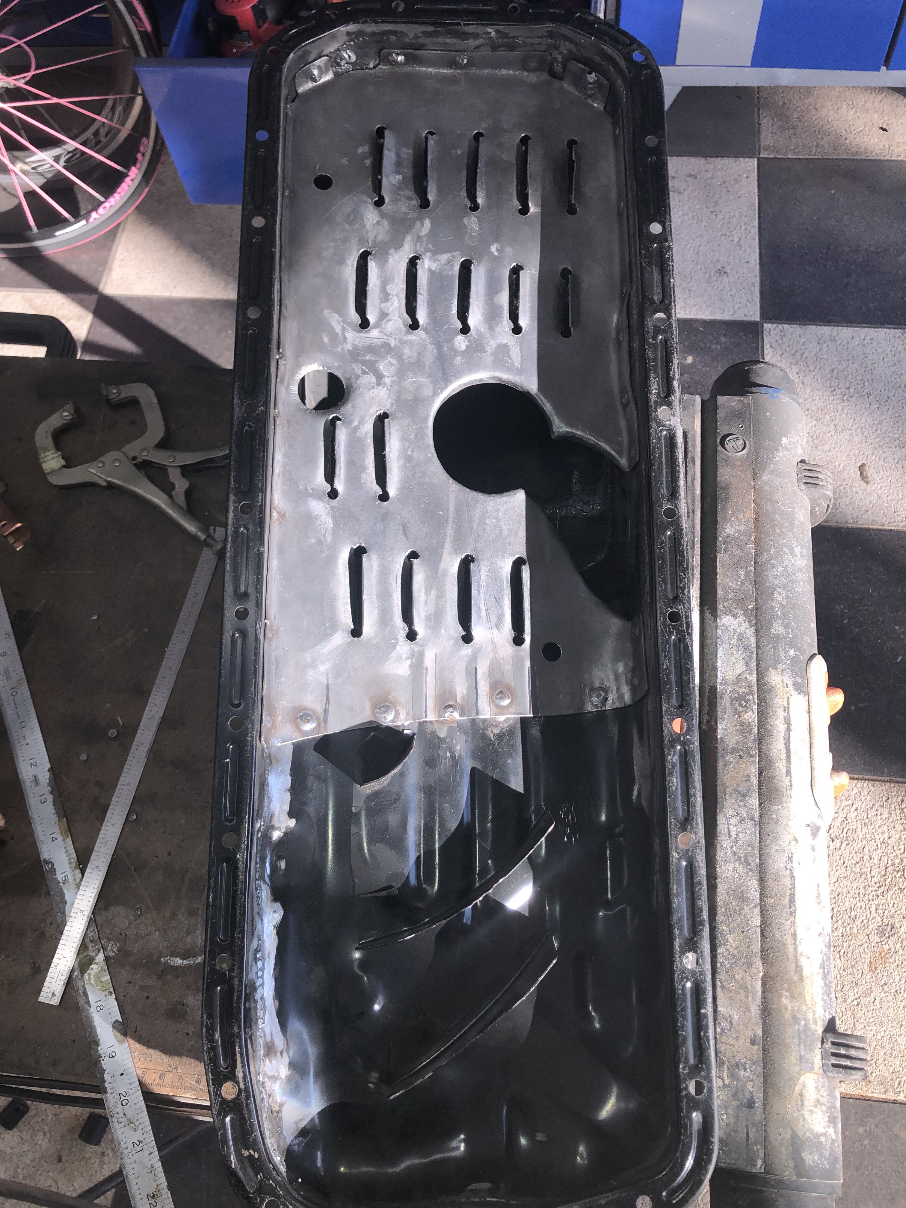
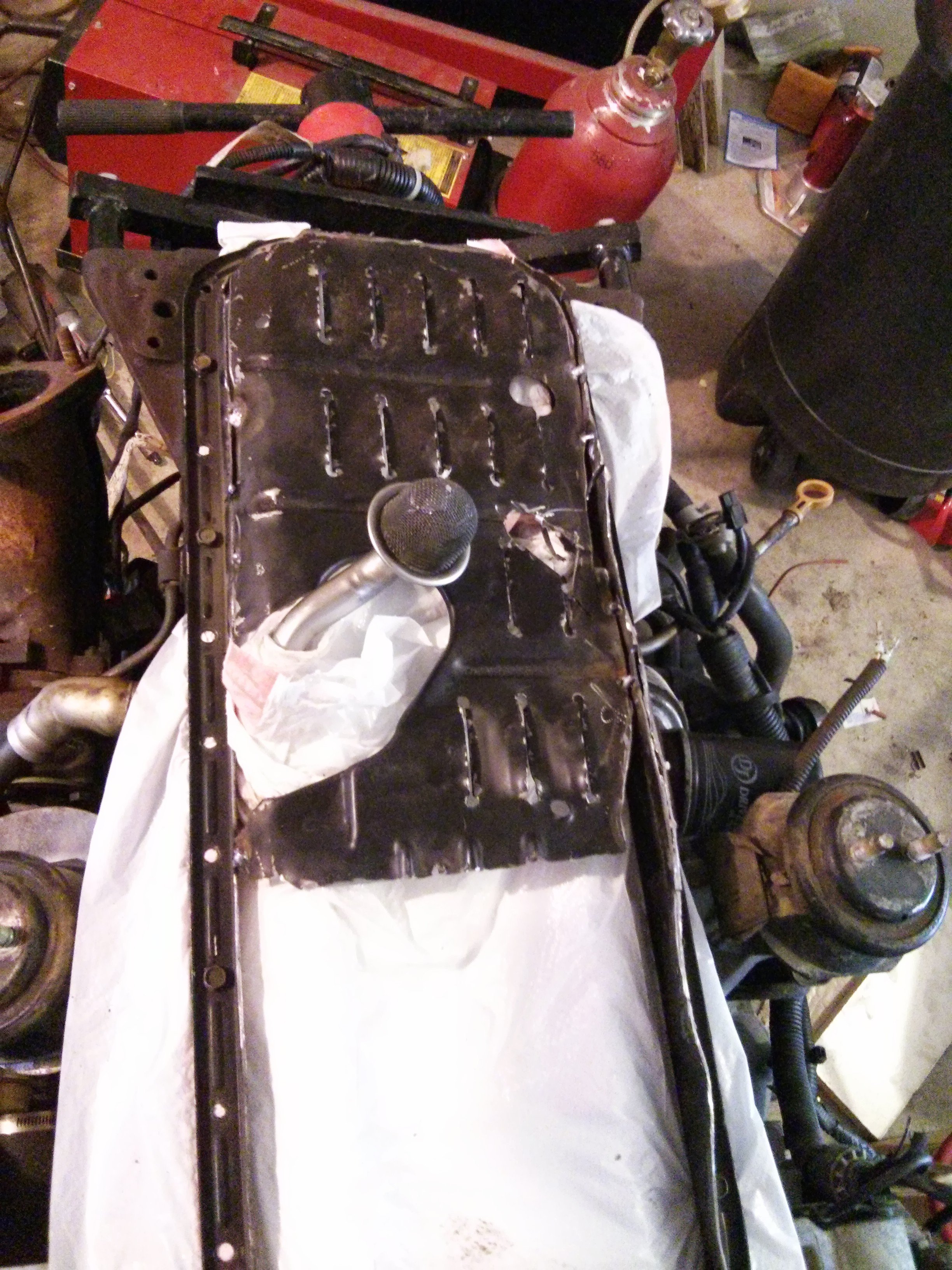
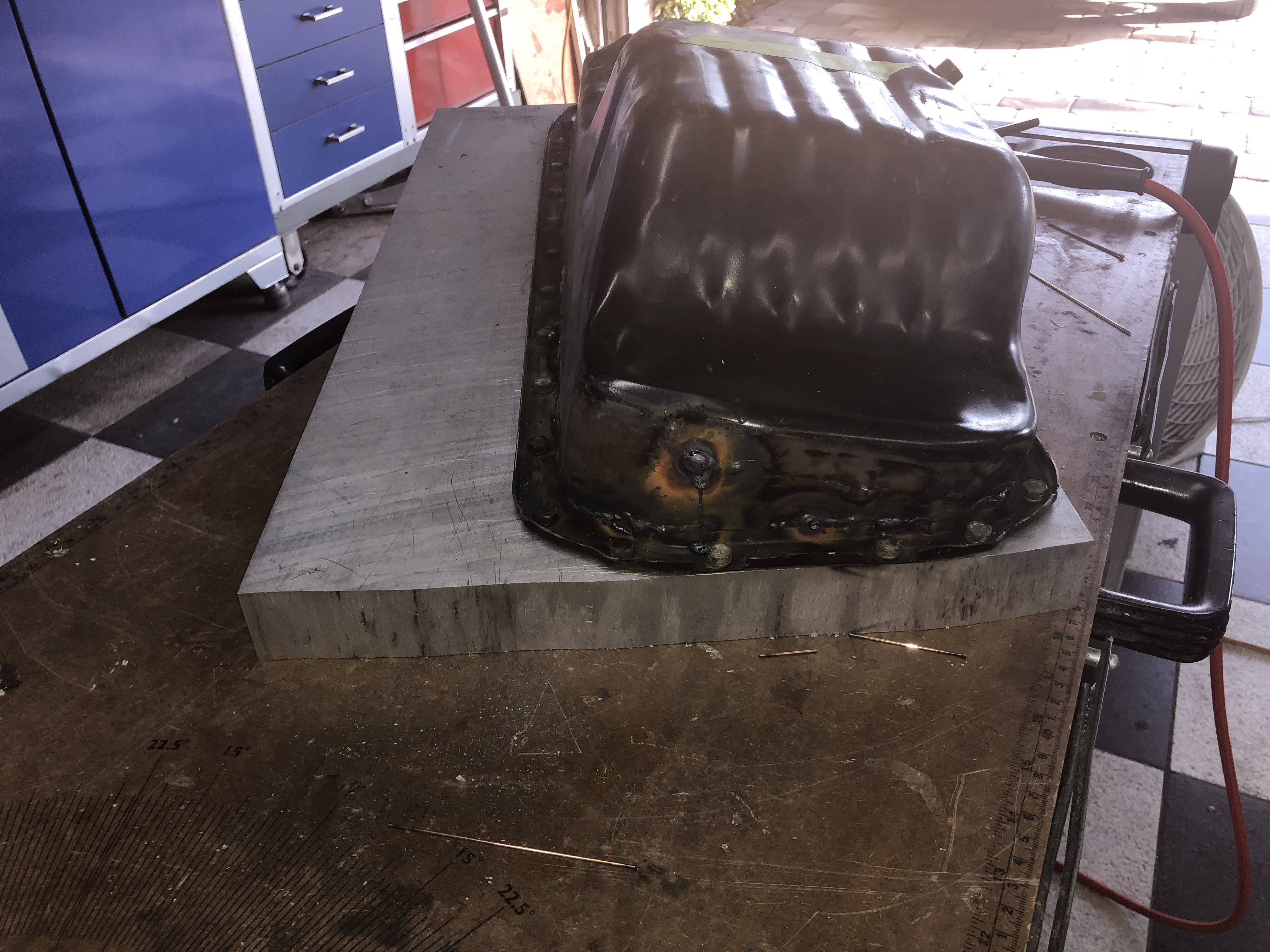
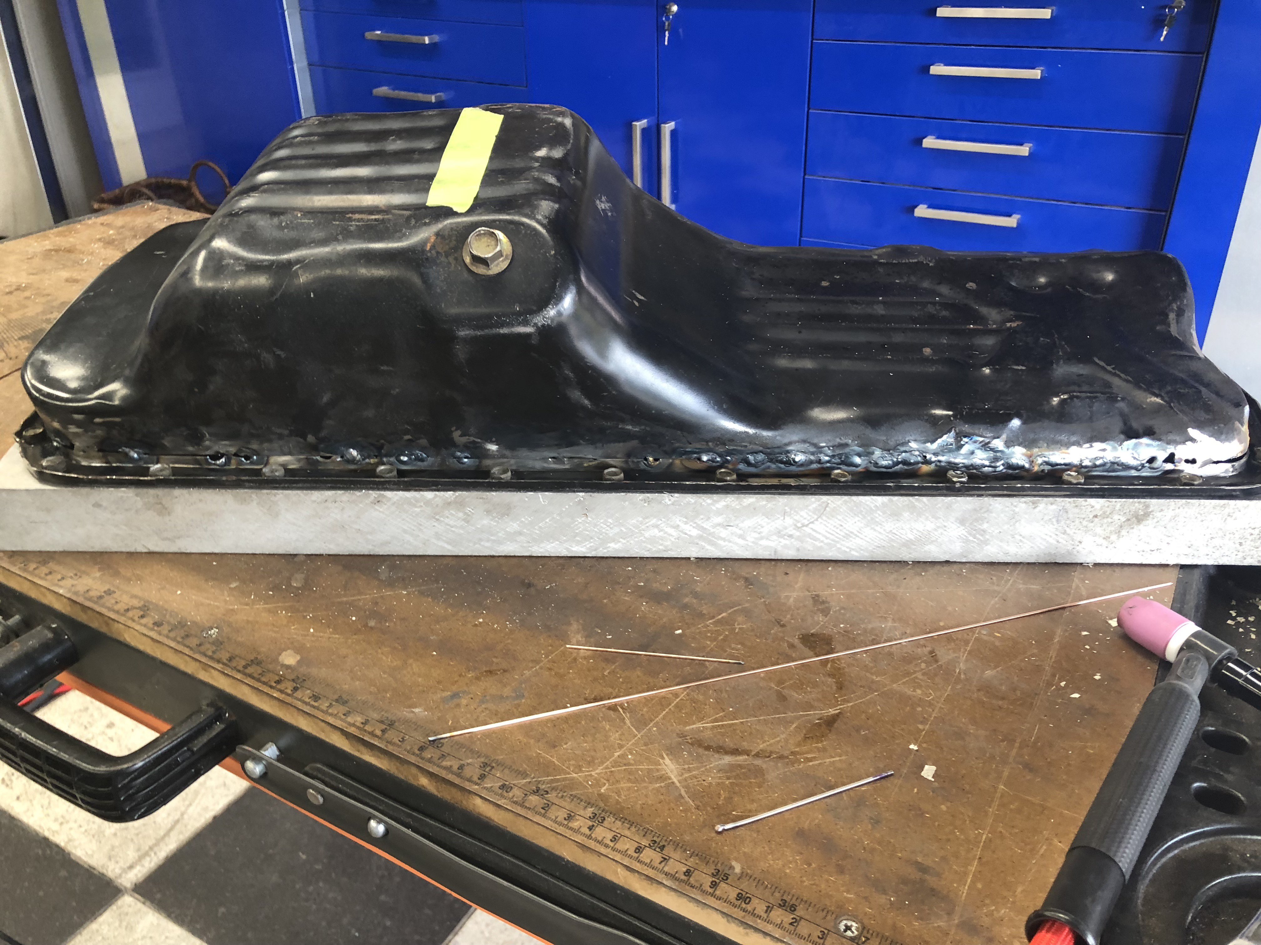
Today’s project was to fabricate a new windage tray for my modified oil pan. The oil pan is now complete except for leak check of all my welds. I ordered an extra pan gasket today, once that arrives I’ll bolt the pan down to the aluminum slab that I have then pressurize it through the drain hole and soap check the welds...once that’s complete I can finally close the lower end on my engine.

-
4 hours ago, mtnickel said:
If you were really OCD, you could silicone your pan down to a flat surface and then pressure test it through the drain plug.
I like this idea, since I already have a slab of billet aluminum I bolted it down to to prevent warpage i’ll Just bolt it down to that with a pan gasket and pressurize it as you suggested. Great idea, thanks!
-
5 hours ago, mtnickel said:
If photobucket didn't destroy my rb25 build thread, you'd see we arrived at the exact same mods (Circa Aug 2013). mine however stayed looking like your original version. Haha.
To account for the cant of the engine, I simply cut off at an angle. Windage tray I put back in as is, but bent all the louvers the opposite direction. Sump, I wish I had some fancier measuring tools. Once the welds were ground and painted, it wasn't so bad. I may remove it and add some trap doors and wings for extra capacity. All this RB oil woes makes me nervous (though I know it is mostly overblown).
Nice work on your 2nd attempt. Looks amazing.
Did you have any issue with leaks? I’m trying to think of a good method of leak checking my welds.
-
2 hours ago, Ironhead said:
I hear ya man. I have dealt extensively with all three of these companies over the past year or so, and I have had at least moderate issues with each one of them. Not just them....but other Z suppliers as well. Misquotes for delivery, quality problems, you name it. I think it's like you say....niche companies with little or no competition.
I am currently waiting on parts from Carbon Signal (Dubai) and Restored.jp. I was QUOTED several months for these parts, so needless to say I am a bit apprehensive as to when they might arrive.
In contrast, I have recently been fitting out my LS3 for the car, which has meant dealing with Summit Racing. What a breath of fresh air. I get 90% of the stuff I order from them next day with ground shipping, returns are quick and painless, and nearly everything is in stock and ready to ship. Probably not a fair comparison though....Summit being a giant, state of the art retailer.
Your build is looking great BTW.
Thanks for responding to my vent session...I appreciate your feedback!
-
5 minutes ago, Jboogsthethug said:
It doesn't even look like you flipped it, awesome job! I'm impressed for sure! Also, where did you get that huge aluminum chunk?
Thanks man, the second attempt was definitely yielded a better result plus I had the original pan to cannibalize. The slap of aluminum was scrounged from the shop that maintains the aircraft I fly. It was so billet material they had laying around and the were good enough to give it to me. I drilled and tapped it so I could bolt the pan to it to limit warping during the welding of the flange. Worked great!
-
Put most of my bare metal in epoxy primer this week. No more chasing flash/surface rust. Not too bad for spraying in my rather dusty garage.
-
On 12/5/2018 at 11:04 AM, winstonusmc said:
I did this very thing. The deal to get the strut tube to clear the CV boot is to kick the bottom slightly to the rear. The strut isnt perpendicular to the ground anyway and leans slightly towards the front of the car at the top, so kicking it out at the bottom isnt a big deal. If you see in my picture, the strut is threaded way down. The way it is now, the car can be lowered way further than the stock BC setup. I might redo it in the future and slide the tube higher so I can weld it differently. You have to be careful not to put too much heat into the strut tube as to not warp the threads. Mine are still pretty tight due to the warping. I am not a pro welder, so a pro welder might do a better job at minimizing the warping. I dont have any clearance problems, but that may be due to making my own tabs to place the strut in a better position. I oversized the upper holes to give me some camber adjustment and the camber plates are now at center at ride height with 0 camber.
On another note, I think if I used a TIG welder, the results would be better.
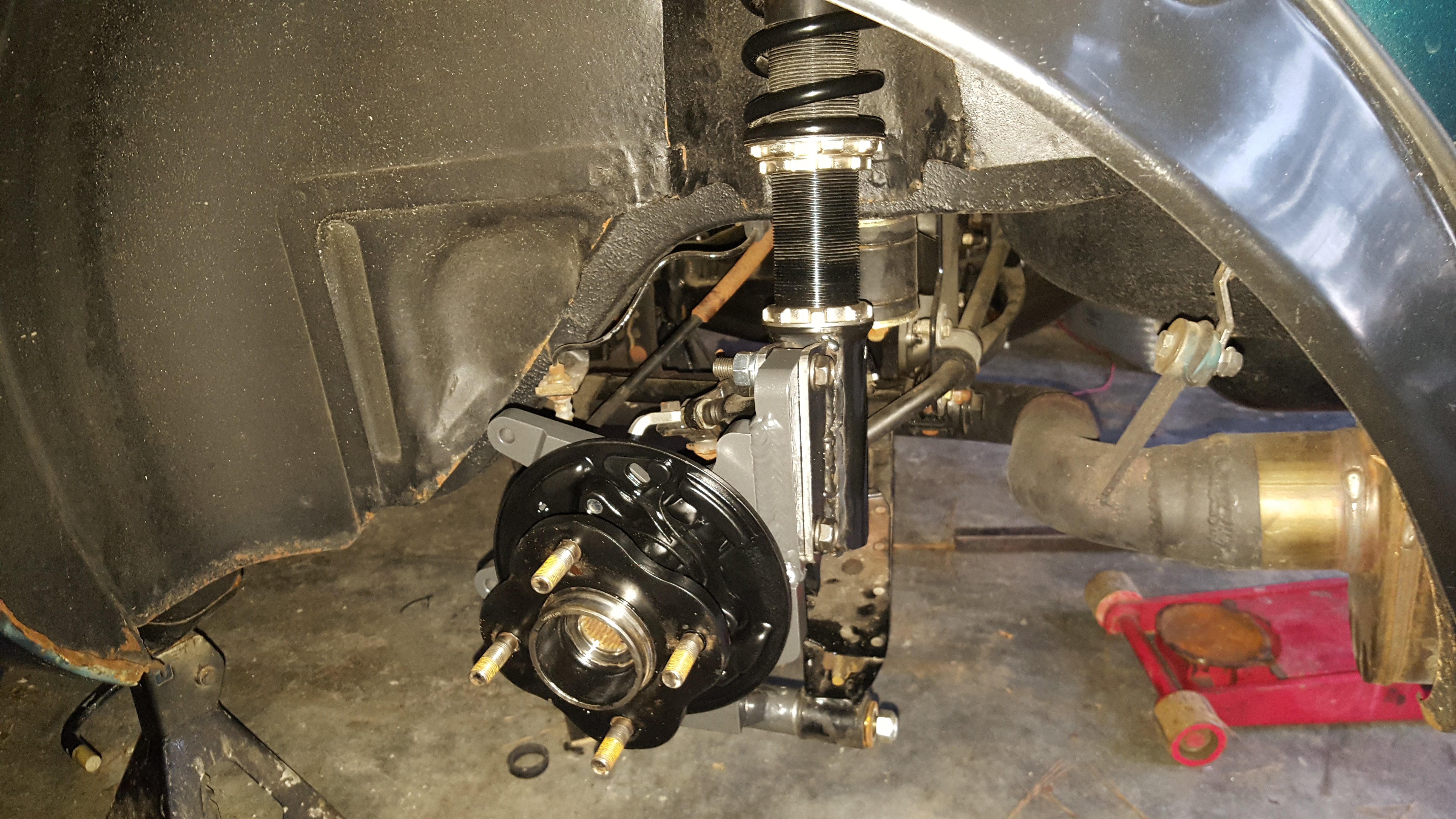
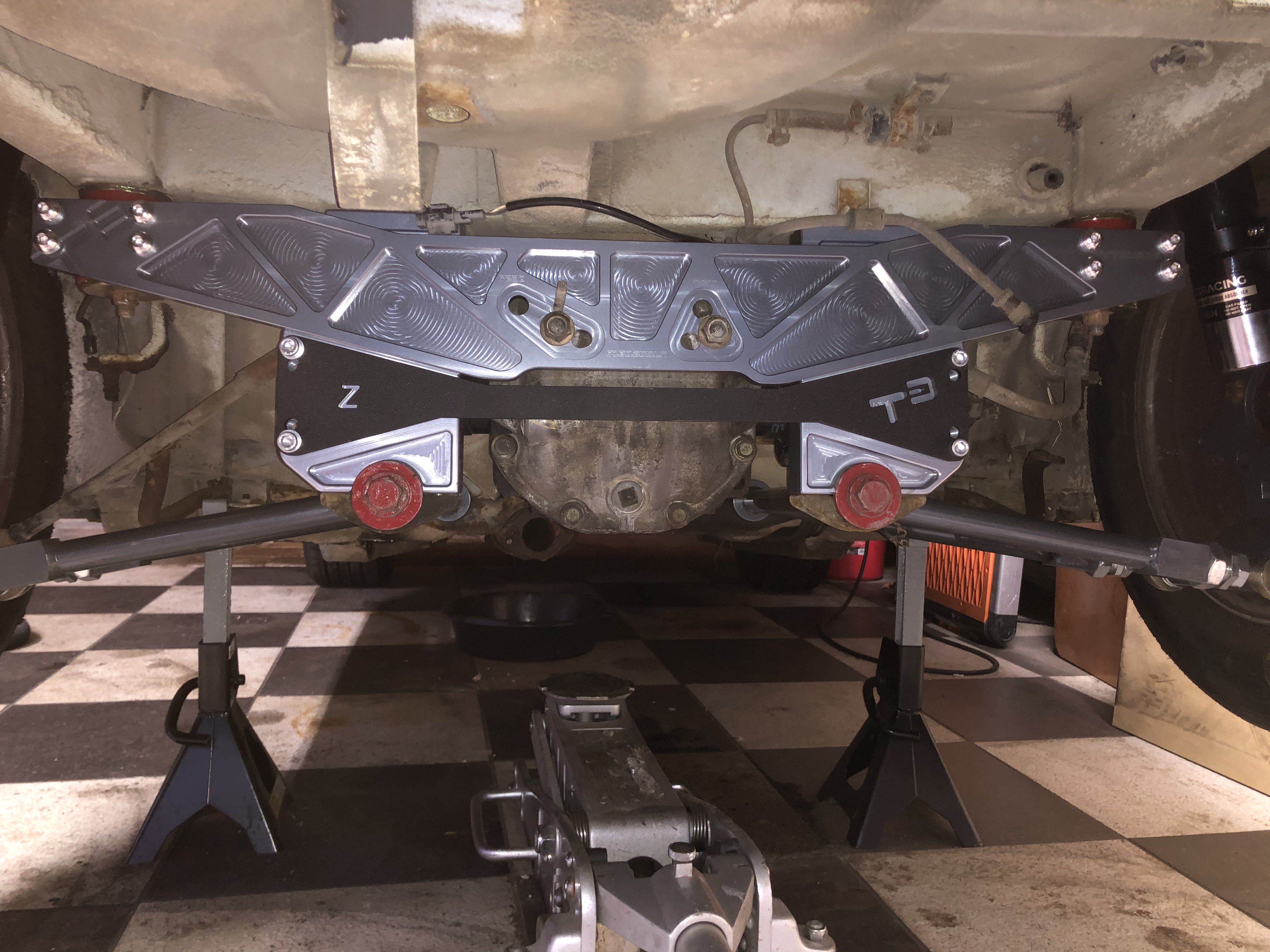
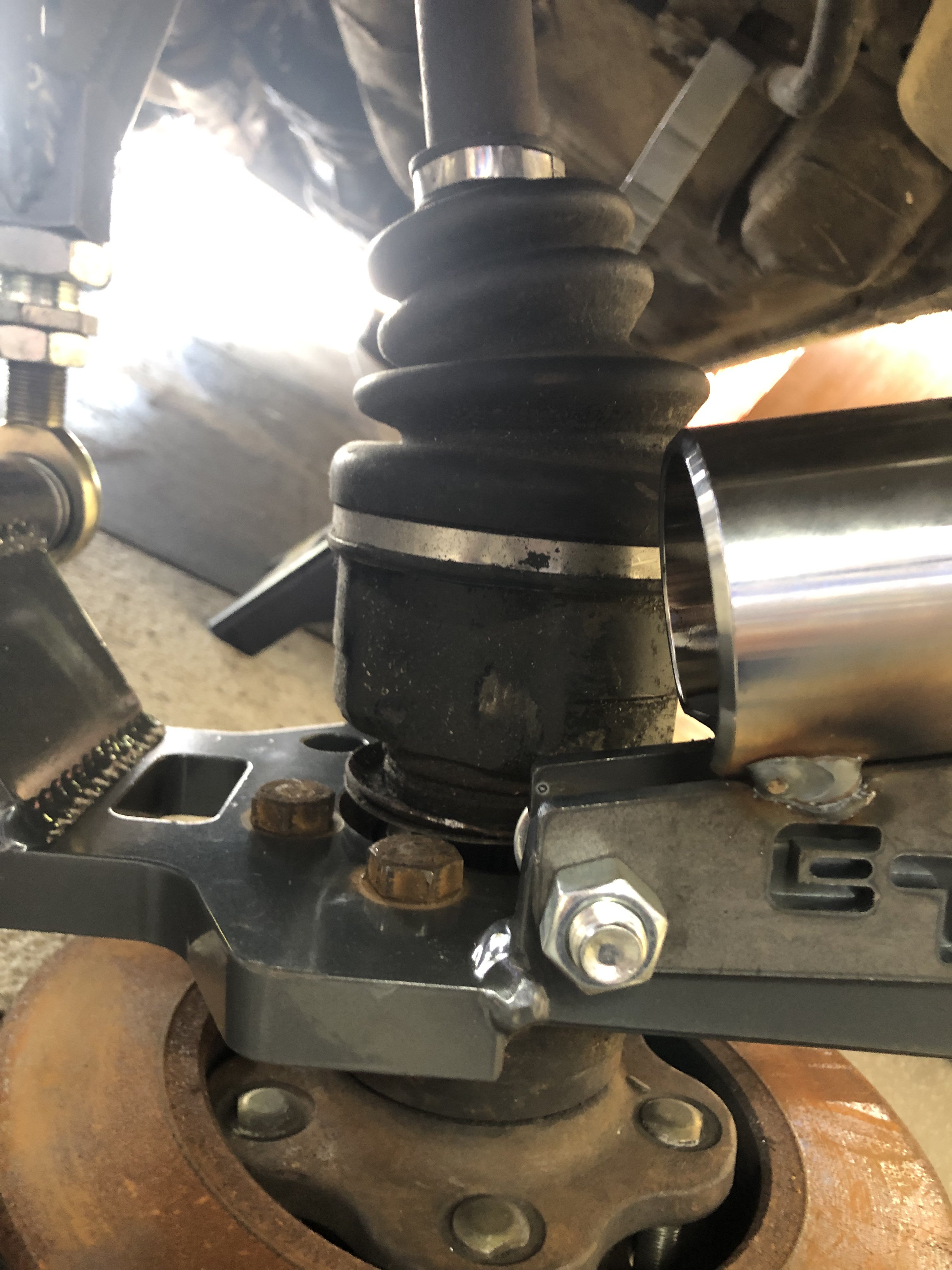
Here are a couple photos of my BC Racing coilovers mocked up in the rear of my car...to cure the clearance issue with the cv joint I lowered the T3 tabs so the are off the end of the BC weld on mount. As far as camber issue my T3 lower control arm are currently extended out on the bottom and the T3 camber plates are adjusted out, once the lower control arms are adjusted in the upper camber plates will bring the rear camber in spec. I’m very pleased with the mock up and happy to be able to use BC stuff on all four corners.
-
On 8/7/2018 at 7:07 PM, Jethoncho said:
Okay, so I have mode some progress, thanks to Jboogs I was ready to start welding on a pan that at minimum wouldn't have worked and at worst might have starved my engine and blew it up. I originally cut the flange off and started to get ready to weld it back on to reverse the sump, I have since added a 1 3/4" filler to the right side of the pan and tacked the sump in place. This gives the bottom of the sump a 1 or 2 degree tilt toward the drain plug side of the sump when installed on the engine (assuming a 13 degree tilt of the engine toward the driver's (left) side.
Try not to be too critical of my TIG skills, its a work in progress as are my welding abilities.
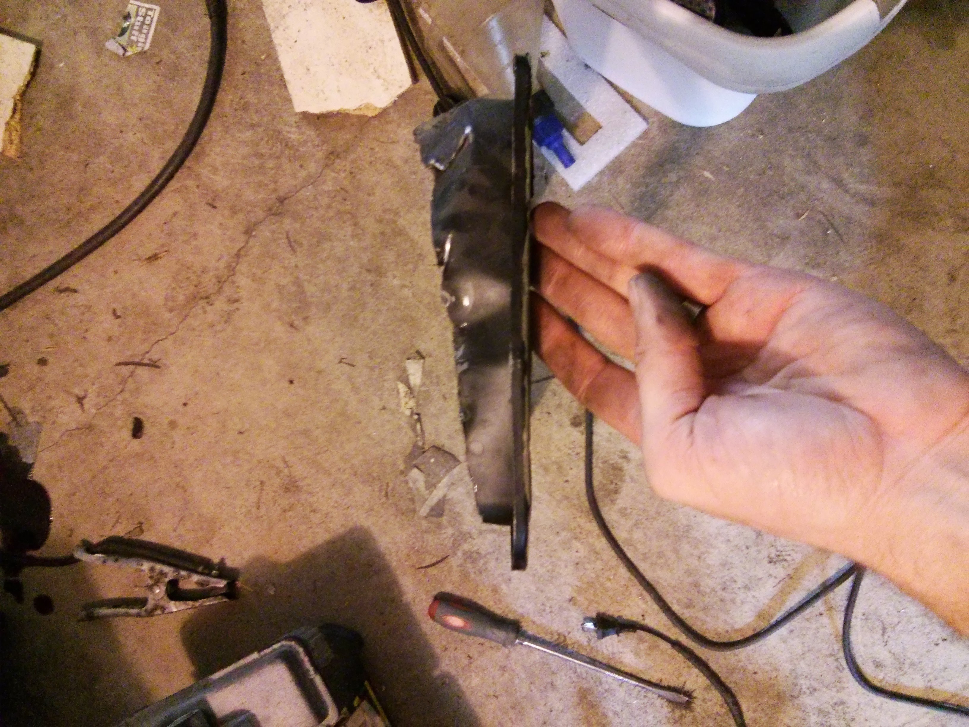
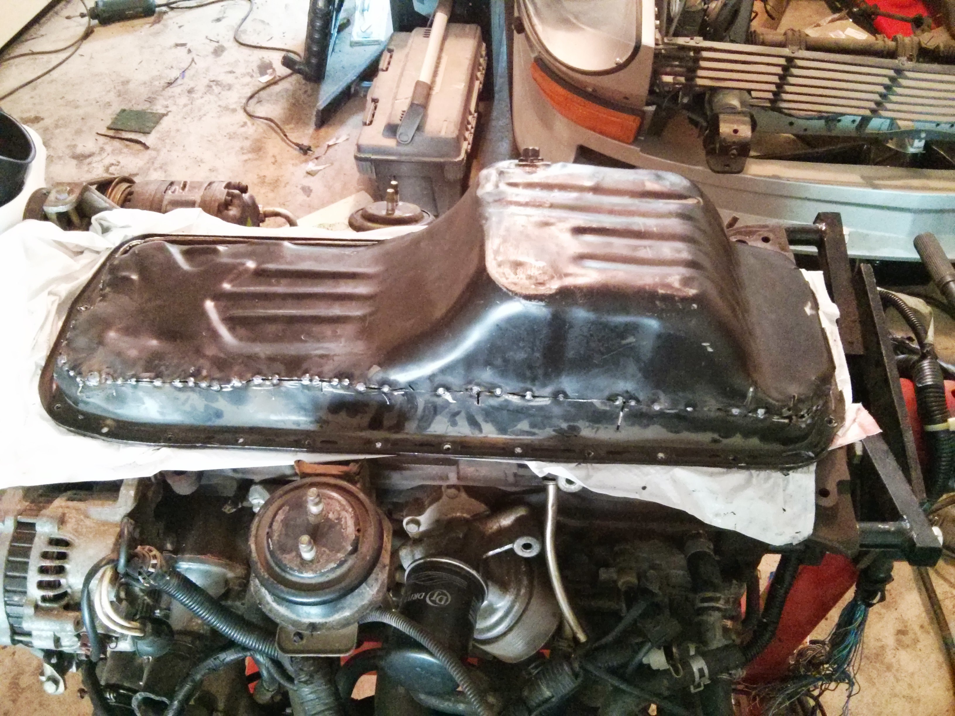
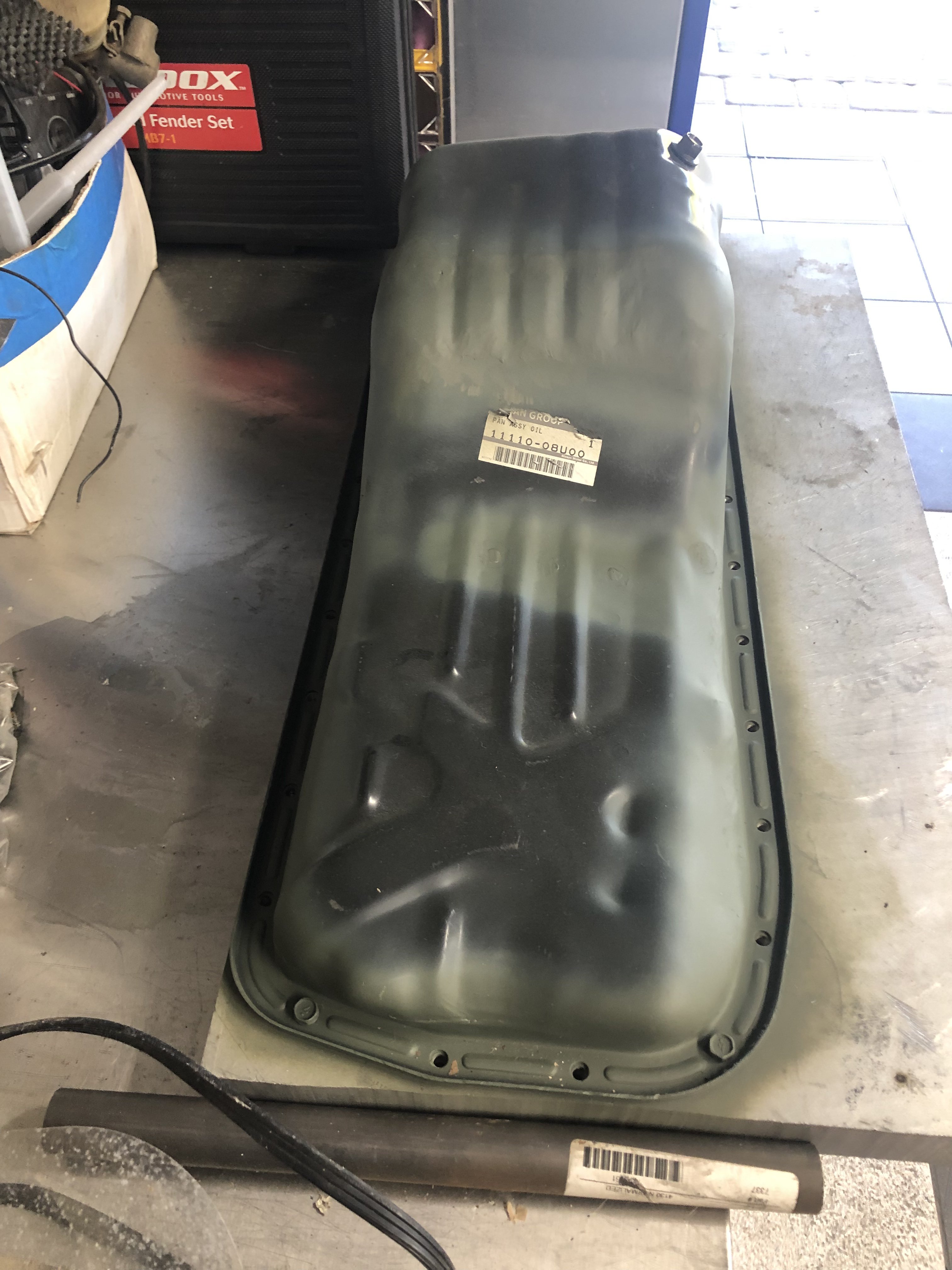
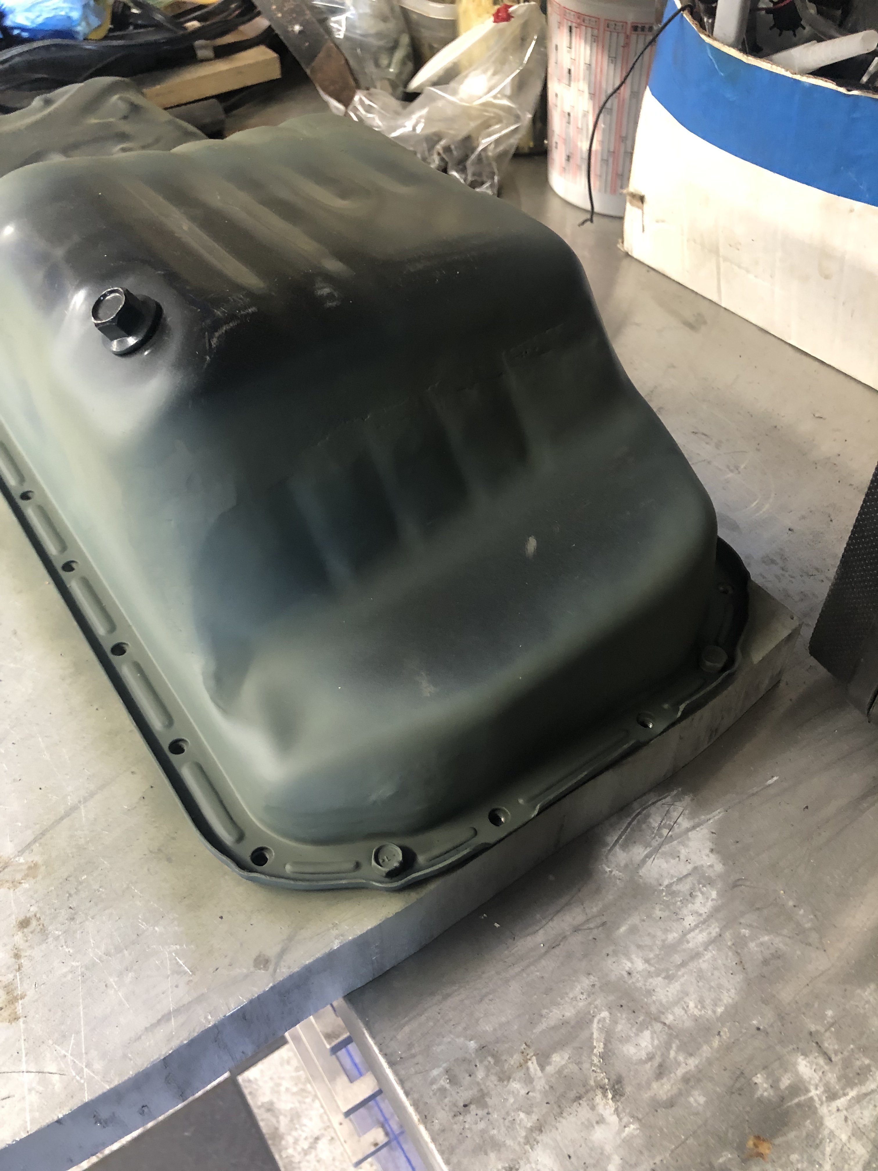
So I threw in the towel on my first attempt at modifying my oil pan to a rear sump. I didn’t like the way it was going...I decided to start over so I bought a new front sump pan.
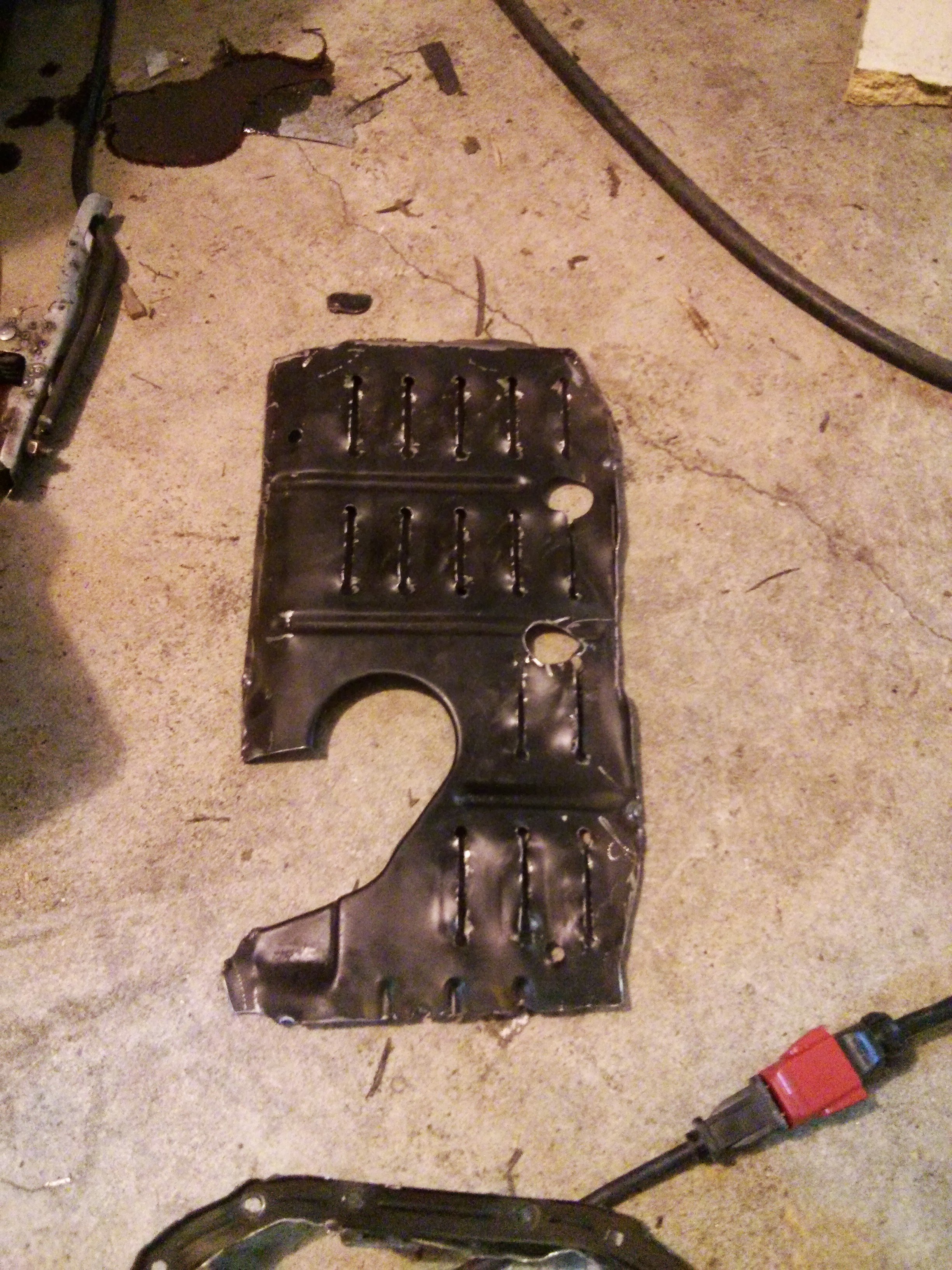
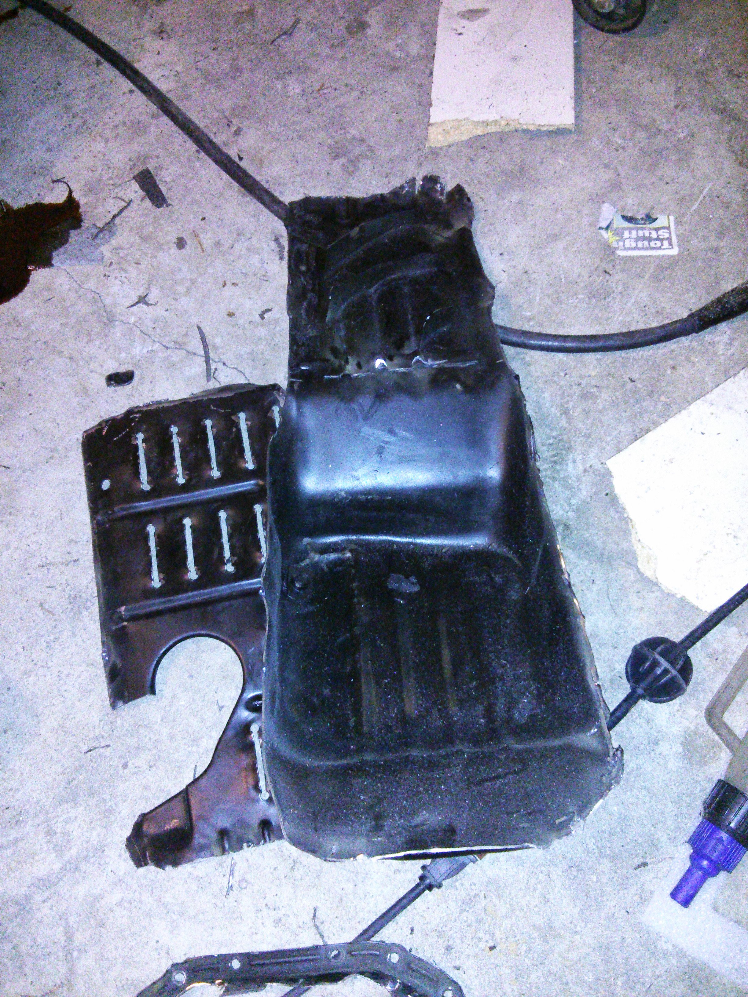
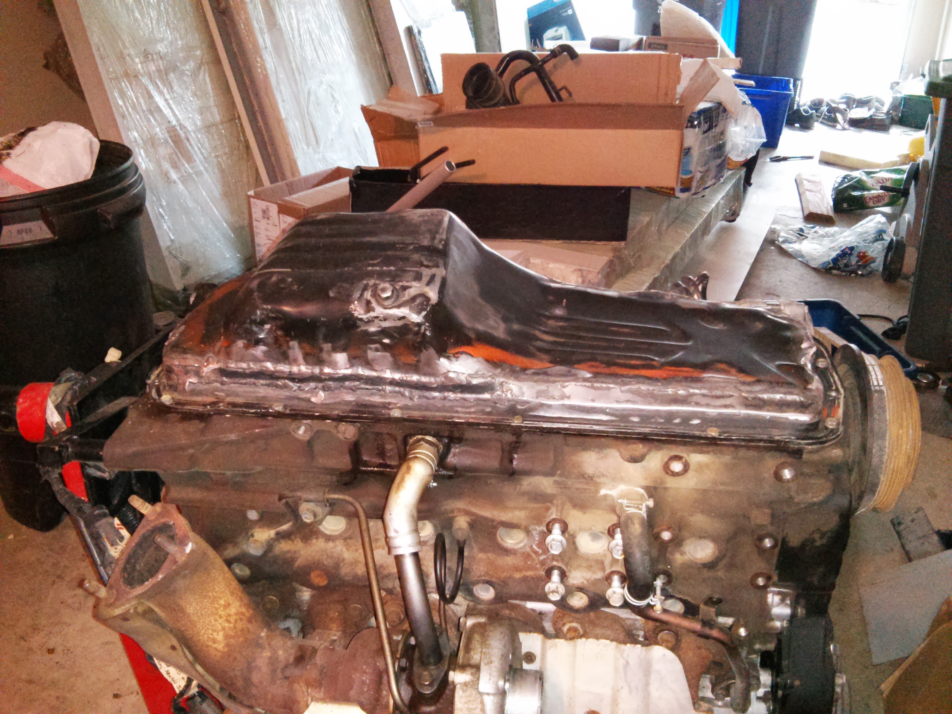
Here is my frankenpan for my RB25 (attempt number 2) I converted it to a rear sump. First, I sliced off the mounting flange and reversed it. This required quite a bit of additional mods as the shape isn’t exactly the same. Then once this was done the sump had to be addressed since the engine sits in the car at approximately 12 degrees tilt to the left. This meant the sump bottom would now tilt 24 degrees...I sliced off the sump which again was no where near the same shape when reversed. It was necessary to graft in a couple of pieces from a donor pan that I had to account for the different shape on the new front of the sump. I still have to address the windage tray but I intend to just remake it so that should be fairly straight forward. The primer shows the areas that received modifications. I guess I could have gone out and bought a pan from one of the vendors that make them but I wanted something that looks OEM and I enjoy the challenge.
-
On 12/30/2018 at 8:08 PM, Nelsonian said:
Watanabe now offers a two piece 17" wheel (RS8) in both 4 and 5 lug options, but in different offsets. There are a few companies, (http://love20bee.com/), (http://wheelflip.com/) that are re- barreling these to fit whatever your needs are. Tire options and a classic banana spoke style are now an option.....
Have you talked with either of these companies to see what they charge to re-barrel a wheel? Are we starting a new thread?
-
Is anyone else going crazy with S30 vendors? Retro-Spec Carbon is driving me crazy, my parts were suppose to ship 12/21 (after over 4 month of waiting)...they didn’t, Techno Toys Tuning orderedrear end swap kit, shipped me incorrect axles and CV boots (after 2 months still waiting for correct axles). Apex Engineering, promised two weeks on their cross-member with RB mounts after 4.5 weeks still waiting...
These guys are niche companies so I guess they can get away with these kind of shenanigans. Seems to me they would quickly go out of business if there was greater competition.
-
1 minute ago, boosted300 said:
Leaving everything better than you found it...nice.
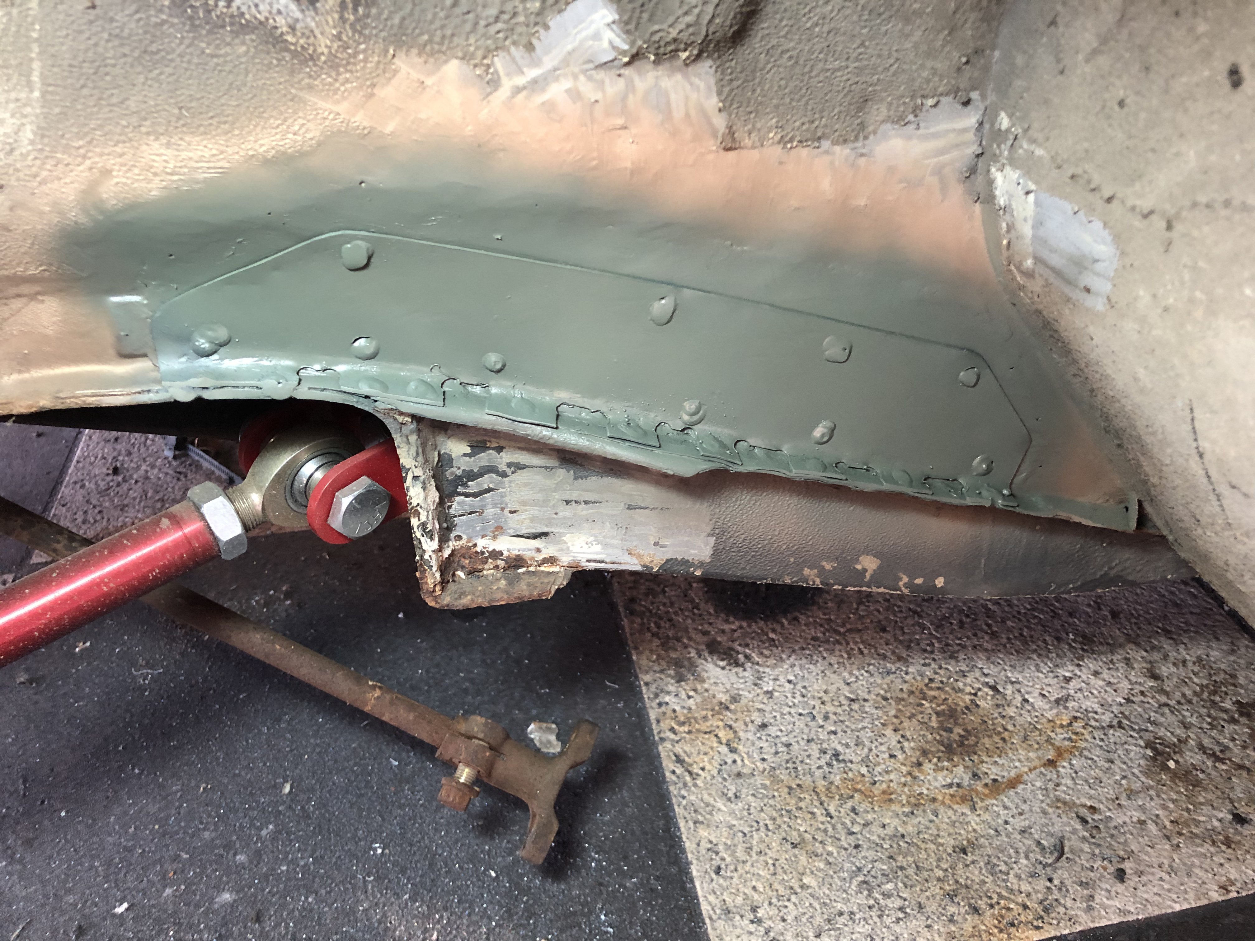
Finished the repair yesterday... Complete the butt weld patch and added the plug welded reinforcement panel..I’ll likely dress down the plug welds but structurally it’s repaired.
-
1 minute ago, boosted300 said:
I'm torn on this...obviously going to 5 lug gives you exponentially more wheel options...but I really love the look of the Watanabe/Rota/Pana style wheel.
Ideally, I'd love some Watanabe 5 lug 17" wheel in the offsets I need, that way I could try other looks and if I didn't like them I could always go back to the Watanabes.
Ultimately though 5 lug is the way to go.
I’d be happy to step up for 17” Watanabes in the needed offset, problem is, I don’t think they exist.
-
1 hour ago, boosted300 said:
Yeah, group buy is a great idea...why don't you spearhead the Volk negotiation? If you send them one of your rudimentary drawings they might be so impressed that they'll do it!
Haha
-
1 hour ago, boosted300 said:
Sure thing brother I will try to do it sometime this week if possible.
Regarding the group buy, I think it's important to remember my suspension setup. This offset might be unique to an AZC suspension, or at least a suspension that is adjustable horizontally, ie adjustable all the way inward.
The other thing to consider is the lug pattern....Volks are awesome (I like the CE28's and also the TE37's)...however anything other than the two wheels you listed would require a conversion to 5 lug.
I am already converted to 5-lug.
-
7 minutes ago, Kbhead said:
Hello Boosted300,
Is it possible to take measurements backed by pictures of the inside if your rim the next time you take your wheels off, then post it. Not that I don't trust the calculations, it's just seams easier and final. I think the +17 mm is accurate.
2nd, Does anyone have access to a vendor that would be interested in making wheels with this offset for a group buy, with a matching pair for the front?
I would be very interested in a set 17" or 16". First choice would be Volk Racing TE37VE , 2nd ROTA.
thx
I like the group buy idea, problem is, I have tried to communicate directly with Rota but if I remember correctly they are in the Philippines and were not very communicative. Maybe Volk Racing might be better?
-
16 minutes ago, fluidmotion said:
Nice patch. Had to do the same on mine. Perhaps Datsun knew those panels would be prone to rust and added extra material haha.
Thanks! I think the reinforcement and the failure of its seam sealer is the cause of the rust in this area.
-
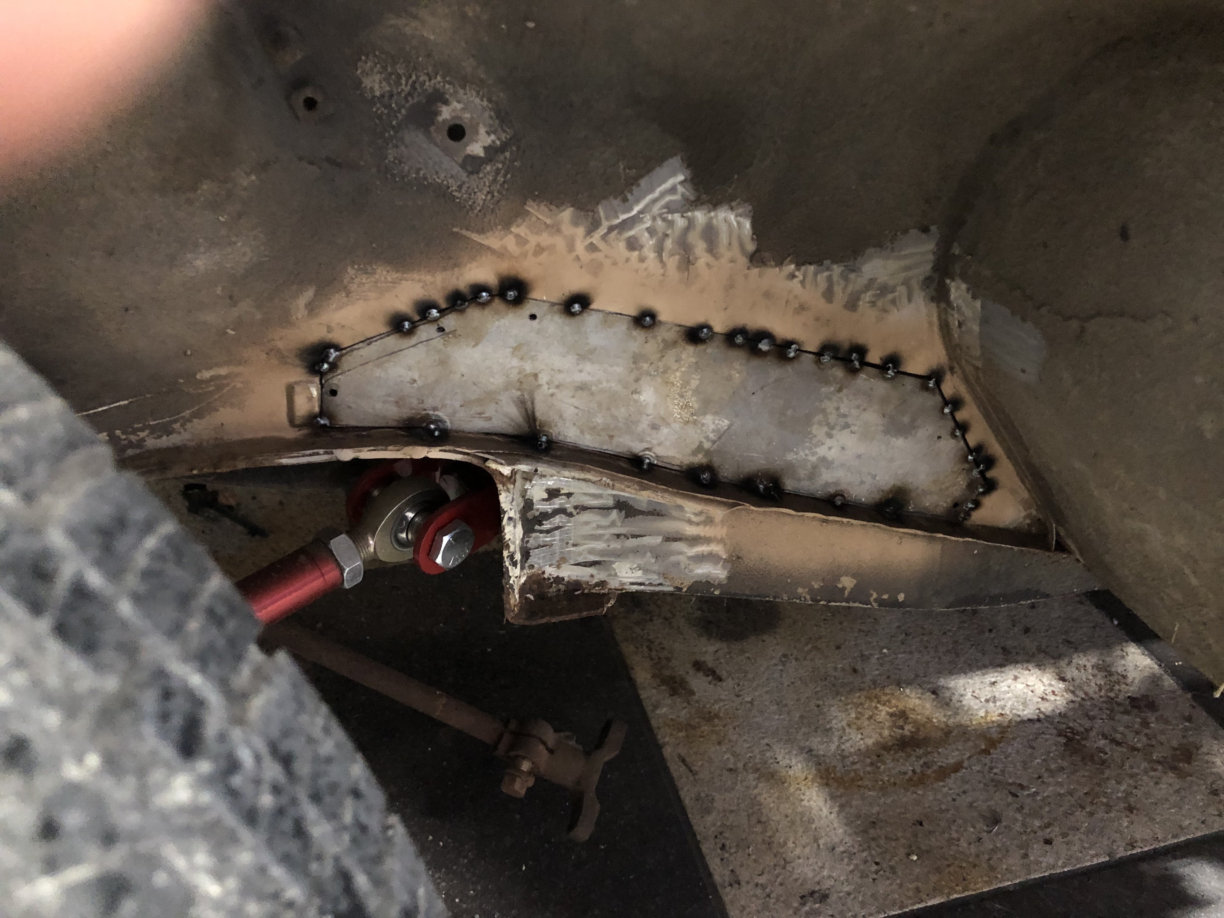
Not very glamorous but very necessary...removed the reinforcement panel to get to the obvious rust behind it. Cut out the rust damaged panel then fabricated a replacement panel. Butt welded (tacked in) te patch panel. Still need to complete the welding then fabricate the new reinforcement panel to install over the patch panel. Not sure what the reinforcement panel actually does as it was original fabricate from very light 20 gauge material. Anyway, the new patch panel and reinforcement panels are going to be 18ga so they will have greater structural strength then the original stuff.
-
Just now, boosted300 said:
Obviously I skipped offset day in school!
Believe me I find it totally confusing that’s why I drew it out just to visualize it.
-
8 minutes ago, boosted300 said:
Lol, I wish I could do a "rudimentary" drawing like that!
Yes I believe that you and, originally EF Ian, are correct...I completely forgot about the fact that centerline moved and failed to account for that.
Thanks for Illustrating it for me.
Now, (let's see if I get this part right!) adding the 10mm spacer then actually nets a +7?
Bingo, you win the prize! I’d love to see you car
-
32 minutes ago, boosted300 said:
Sorry for the tardy response!
So I'm still not positive on this but in thinking more about it...
The original wheel was 8.5 +4... since I added 1 inch (25 mm) to the inside only, wouldn't it be the full 25 instead of 1/2 of the 25? or +29?
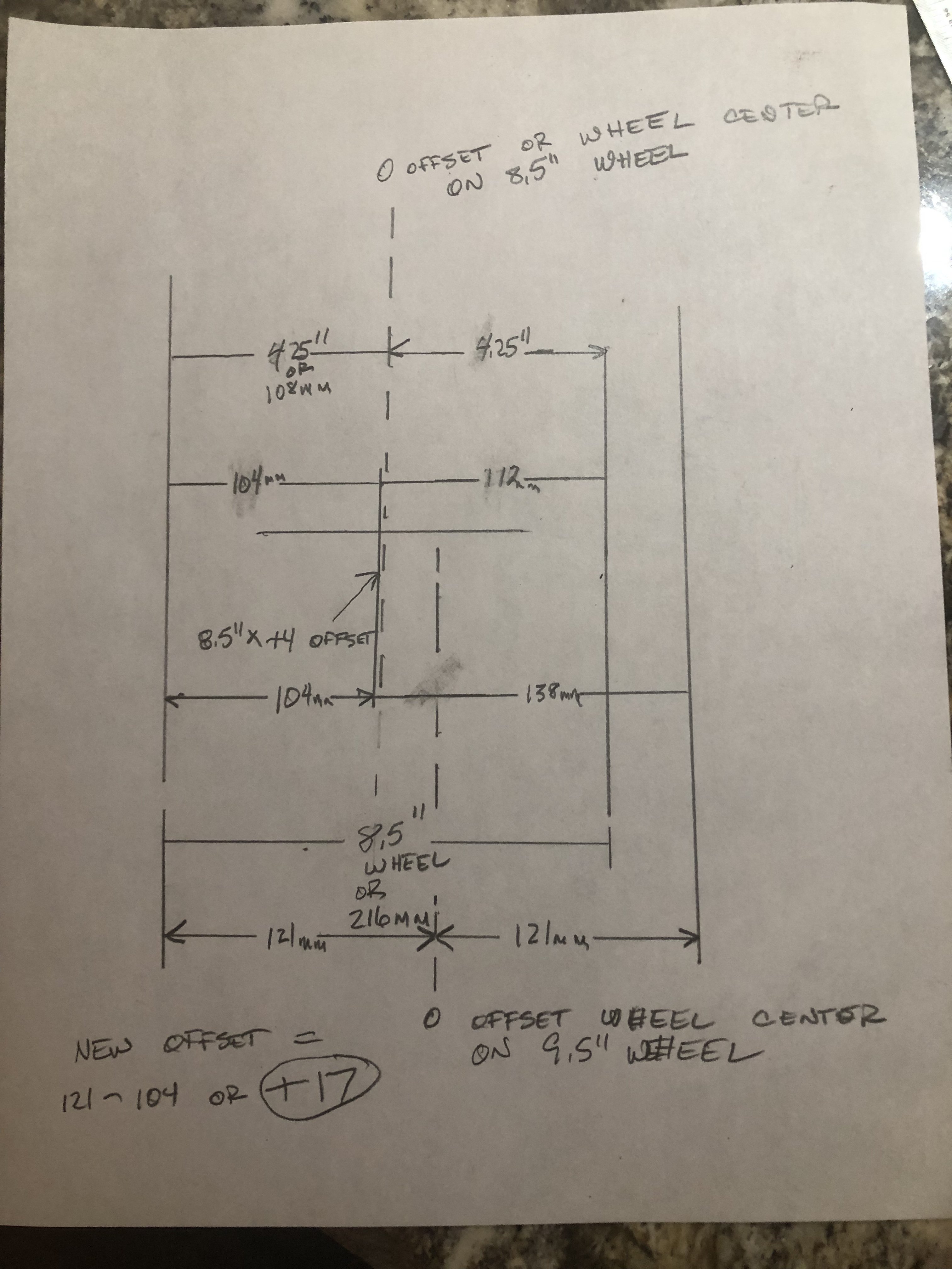
Hello, I get what you are saying but you have to remember that offset is based on the distance from the wheel centerline. On the 8.5 inch width wheel you had a +4 offset or 4mm closer to the outer lip of the wheel based on the center of the wheel being an equal 4.25” from front or rear lip. Then you added 1 inch (or 25.4mm to get with the same measuring system used in the offset). Remember while you added this to the back side of the wheel it also moved the wheel’s center line by only .5” or 12.7mm. So if you measure from the new wheel centerline and add the old offset you are sitting at +16.7mm offset on the widened wheel.
I did a rudimentary drawing to illustrate my opinion. You can use the new changed centerline measurement (121mm) minus the unchanged distance from from the outer lip (104mm) to arrive at the new offset of +17 (rounded off from +16.7).
I hope it helps.
-
Back to metal work the past couple of days...finished welding on the left rear quarter replacement. It needs a little hammer and dolly wok but overall I am happy with how it turned out. Next the forward section of the left door jamb had a bit of rust neat the hinges. It wasn’t rusted through but I cut it out and replaced it anyway. The upper windshield frame had a small area of rust through...it took a small 2” by 0.5” patch welded in to correct this area. Still to go on he left side...small area on the floorboard (7”x10”), this will be a little work since it’s in the area where there are two drain holes and some bead rolling.
I did take a little diversion to restore a 240Z steering wheel that I plan to use...I bead blasted the metal to remove old paint and surface rust. Next I repainted the spokes with POR15 satin black. After a day to dry/cure, I sanded the simulated wood and newly painted surfaces with 600 grit and applied thee coats of satin clear coat. I am extremely pleased with the outcome...too bad I’m likely a year away from installing it but it is gratifying and does help to keep me motivated.
-
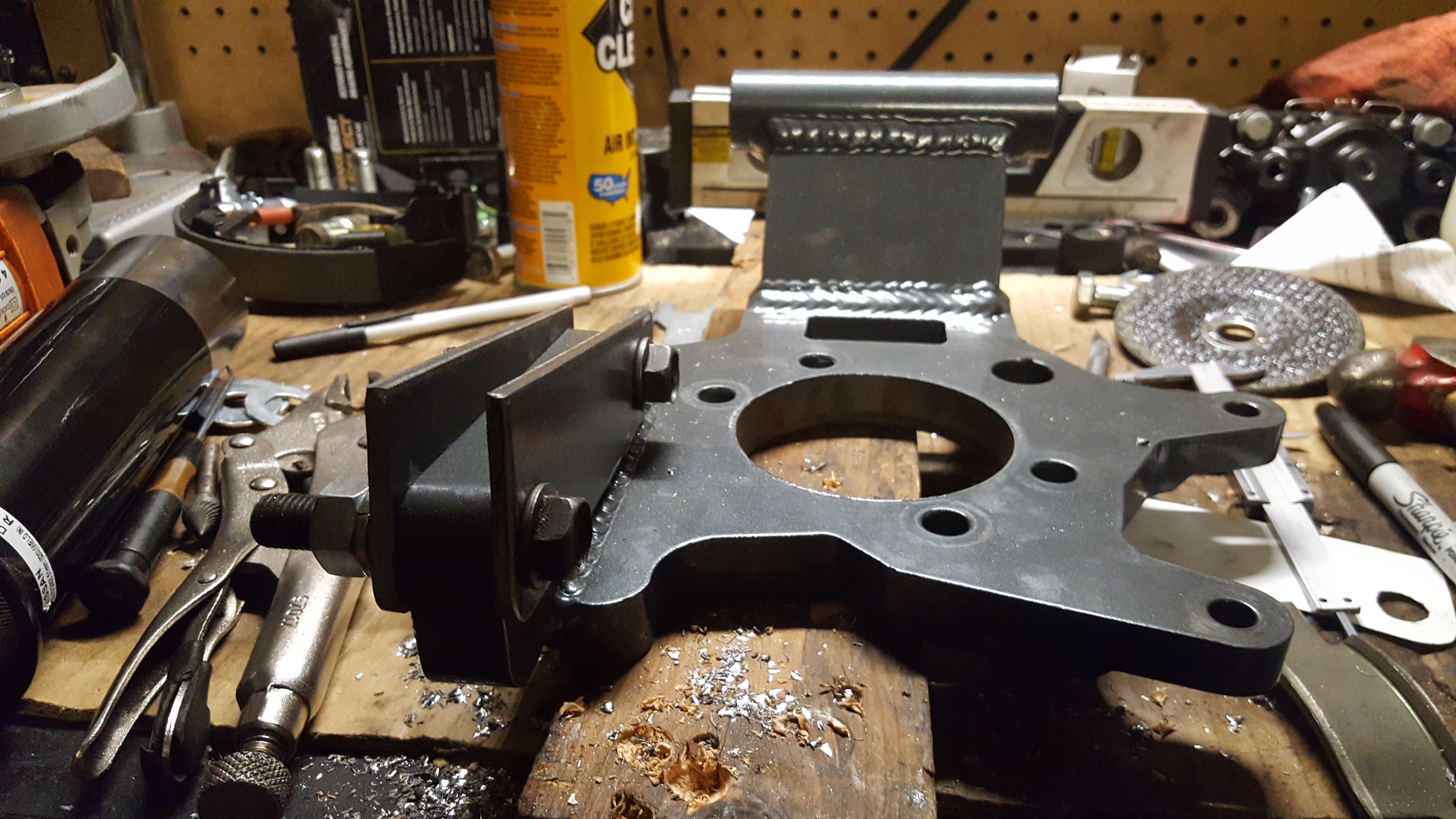
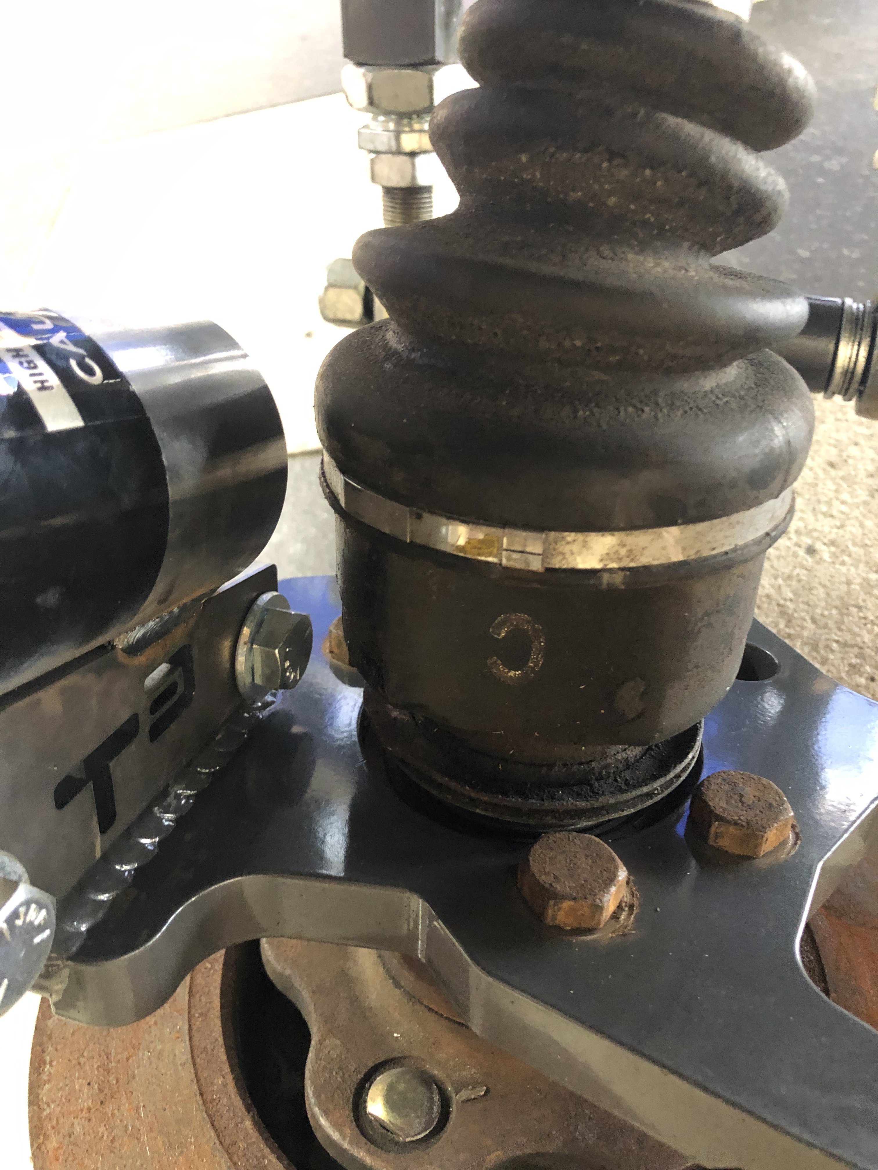
Thanks to those that reached out to me regarding the CV boots clearance on the lower BC coilover mount with T3 mounting tabs. I returned from four days on the road and decided to tackle this dilemma...I previously mocked up the rear suspension and figured out BC sent me a set of front coilovers instead of rears. I contacted BC while I was on the road and they were kind enough to send me a set of rear shocks and springs so I disassembled the rear and built it back up with the new parts while also incorporating T3 camber plates. To use the T3 camber plates T3 sent me bushings meant to integrate their camber plates with the BC coilovers...I decided I wanted to use the BC bushings instead so I took the BC nut and pillow bushing and turned (lathe) the bushing portion down to 15.76mm to fit inside the T3 bearing in their camber plate.
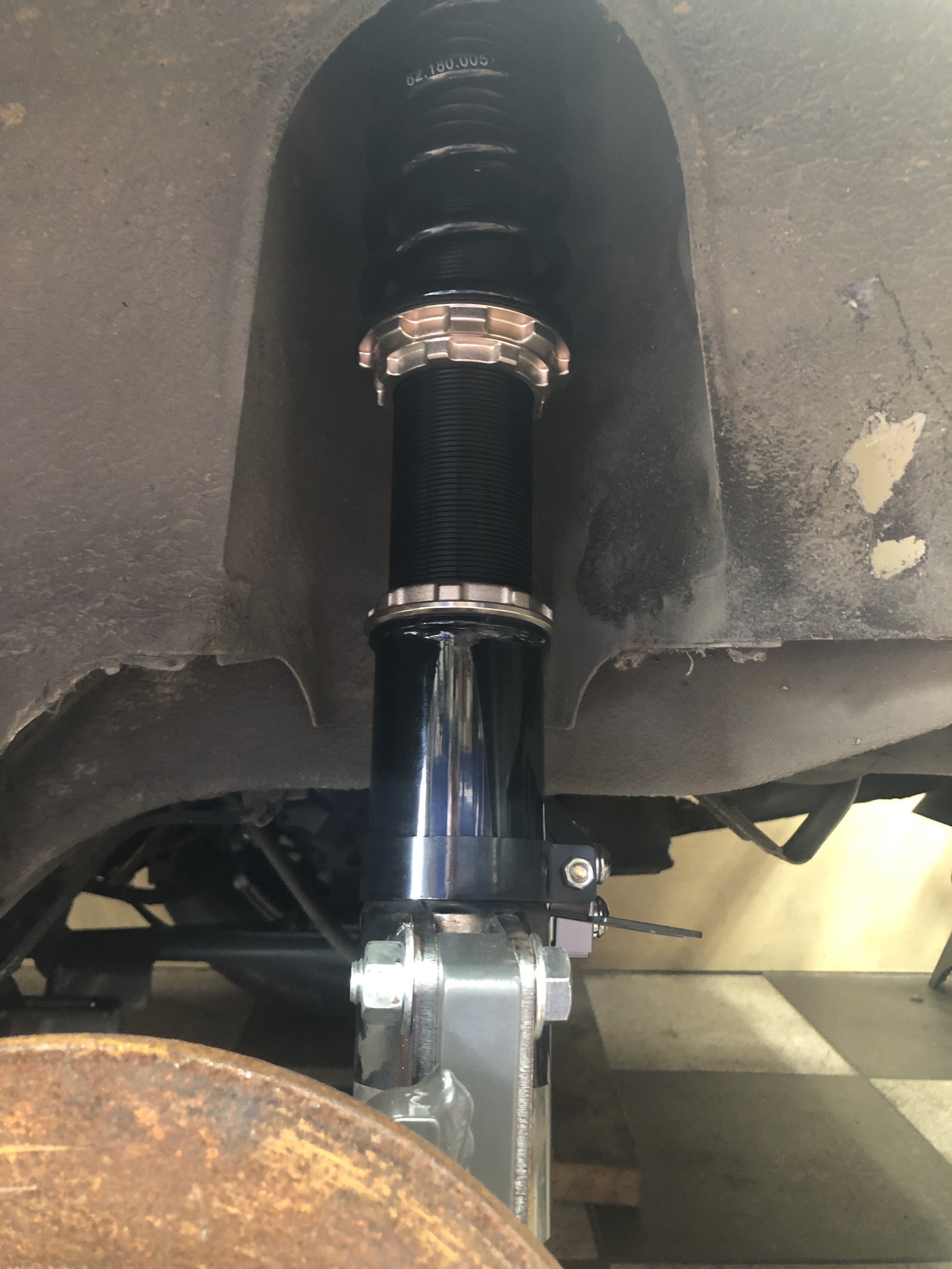
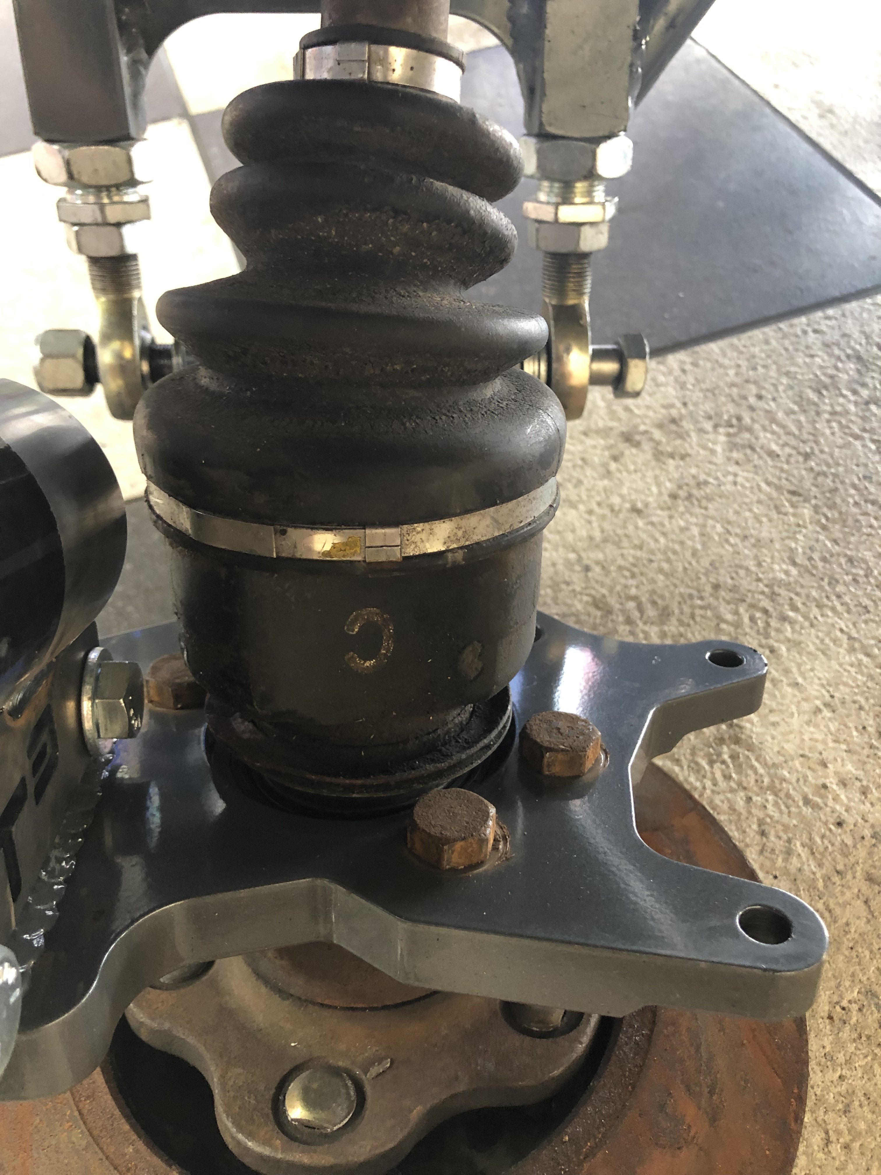
Next after building up the rear coilovers with the correct parts I mocked in an axle and I have good clearance on the CV boot. I attribute this to the fact my lower mounts are likely front mounts and my T3 tabs extend beyond the lower end of the lower mount by a little over an inch or so. My lower mounts have a reduction in diameter about 4 inches from the lower edge so I attached the T3 mounting tabs even with the upper edge of the larger diameter on the lower mount. I posted up a few photos to illustrate what I’m talking about. With the T3 camber plates and T3 lower control arms I don’t anticipate any issue with camber adjustment either.
-
On 12/4/2018 at 4:58 PM, Kevlars30z said:
No problem man. I’ll be keeping an eye on your updates. Since I would love to run their rear setup with my BC Coils. I’m not looking to be spending 2k plus on coils, since I have mine already.
I’ll be updating this thread as I progress. The BC Coilovers are new but they shipped me a set of fronts that are currently mocked up on the vehicle. BC already sent me some replacement parts to swap out to correct this issue. Once I get these swapped out and install the axles I’ll get some more photos up. I am traveling for work so it will be a couple days.
-
6 hours ago, winstonusmc said:
I did this very thing. The deal to get the strut tube to clear the CV boot is to kick the bottom slightly to the rear. The strut isnt perpendicular to the ground anyway and leans slightly towards the front of the car at the top, so kicking it out at the bottom isnt a big deal. If you see in my picture, the strut is threaded way down. The way it is now, the car can be lowered way further than the stock BC setup. I might redo it in the future and slide the tube higher so I can weld it differently. You have to be careful not to put too much heat into the strut tube as to not warp the threads. Mine are still pretty tight due to the warping. I am not a pro welder, so a pro welder might do a better job at minimizing the warping. I dont have any clearance problems, but that may be due to making my own tabs to place the strut in a better position. I oversized the upper holes to give me some camber adjustment and the camber plates are now at center at ride height with 0 camber.
On another note, I think if I used a TIG welder, the results would be better.
Your rear setup looks great! I appreciate your input regarding the requirements to run T3 style tabs on the lower BC Coilover Mount. This is helpful...I’ll keep this thread updated as I make progress.


1978 Datsun 280Z RB25 Restomod
in S30 Series - 240z, 260z, 280z
Posted
The windage tray I attached to the previous post from yesterday is a completely new fabricated part. The louvers are reversed from the original to compensate for the pan/sump being reversed. I’m gonna try to be a little more active with my post cuz I think it helps keep me motivated! Thanks for following my thread!