D1t
-
Posts
11 -
Joined
-
Last visited
-
Days Won
1
D1t's Achievements
")


-
I welded 4x 1.75" wide 0.06" thick strips from the roll hoop to the body, two on the sides right below the window frame and two to the roof support .75" outboard of the dimple die holes. I cannot believe how much quieter the car is and how much better it handles bumps, hard accelerations, sharp turns, etc. Its really incredible, wish I'd done this a year ago.
-
Thanks guys, I'll try a couple of shear tabs between the hoop and the roof support, probably one on each side. Just yesterday I fixed a big rust patch in the dogleg which had been hiding under some bondo (nice job whoever fixed that last 😕 ) and that seemed to stiffen the car up substantially, no more banging when entering the driveway!
-
Hi Folks, when I welded a 4 point roll bar into my 240z I tried to get the top and back of the roll hoop as close to the roof support as I could to give me the most room for seats and helmets. Unfortunately, on the passenger's side its a bit too close, and as the chassis flexes the roof support bangs into the roll hoop making a really annoying sound. I've been thinking of just welding the roof support straight to the roll hoop as a way of preventing this and stiffening the chassis, but I'm worried about this causing issues with flexing the joints in the roof (specifically the joint at the top of the A pillar) and cracking the 50 year old very fatigued steel. The paint on both B pillars has already cracked at the leaded joint and I'm thinking of using a syringe to inject some paint or POR15 to keep it protected. The car is almost only used for autocross at this point but it's still street driven to and from and I don't want to create any new issues. Has anyone done this before, and if so, did you run into any issues? It would be incredibly difficult to get a file in and clearance the roof support where it's rubbing the roof support, but I guess anything is possible. Thanks! Noah

-
280Z build w/ LS3 and 2015 Mustang spindles/8.8
D1t replied to 280Z-LS3's topic in Gen III & IV Chevy V8Z Tech Board
I'm referring to the knuckles I'm building for 280z-LS3 and myself. I reamed out the pivot tube on the knuckle not the arm. -
280Z build w/ LS3 and 2015 Mustang spindles/8.8
D1t replied to 280Z-LS3's topic in Gen III & IV Chevy V8Z Tech Board
I reamed the pivot tubes out to be a light sliding fit on the 5/8" pivot bolts with a hand reamer, they're ~0.627 right now and I'll do it again after welding to make sure they're still straight and cylindrical. The bolt shouldn't ever see the shear load unless the nut becomes loose, but it also helps make sure that your alignment doesn't change every time you take the rear end apart and put it back together. -
280Z build w/ LS3 and 2015 Mustang spindles/8.8
D1t replied to 280Z-LS3's topic in Gen III & IV Chevy V8Z Tech Board
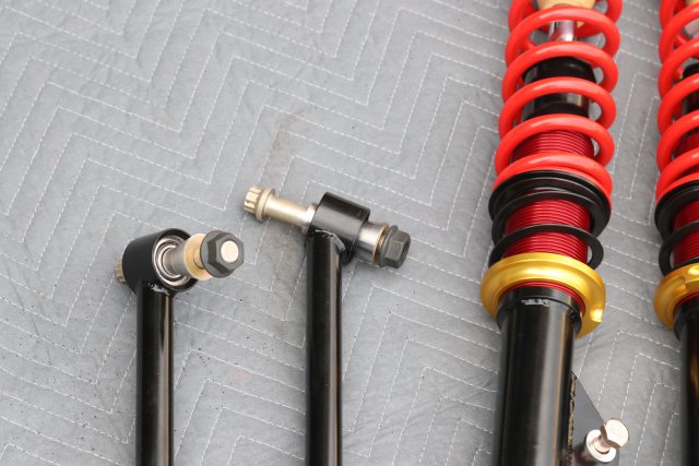
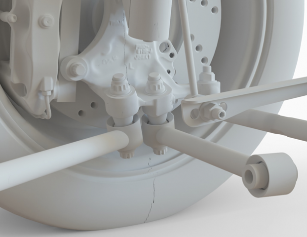
The forward rod end on that arm uses a concentric double adjuster (RH male thread on outside, LH female thread on outside) so I can avoid using a separate toe link while still being able to adjust the toe on the car. This avoids creating a buckling load in a toe link and allows the lower control arm to react some of the torque of the engine/brakes instead of passing all that load up to the strut mount and putting additional bending load into the strut. -
These numbers are all as-installed on 240z. Some of the images show the 2014 spindle and some show the 2015 because I had designed the complete 2014 kit before changing direction. Caster is adjustable by using spacers on the clevis where the rear link mounts to the chassis. 7 degrees of caster is quite a bit, but with zero scrub that's reasonable. There are definitely pro's to moving suspension points around by fabricating new mounts, but I wanted to leave all the stock mounting for a few reasons: Many competition classes restrict you to "stock suspension mounting points" which, I would argue, this uses. I wanted the challenge of doing this with stock mounting points. In case this all went south, I wanted the option to be able to switch back easily. If I were to sell this as a kit, it's substantially more marketable as "bolts right in".
-
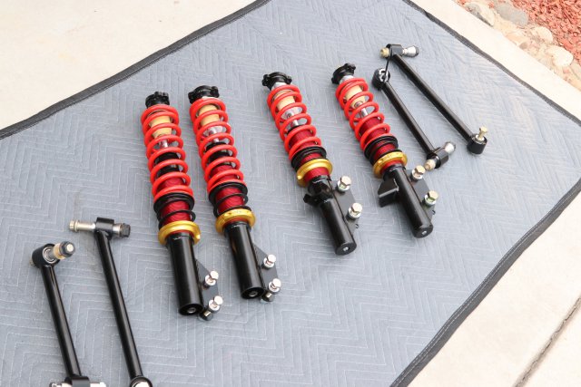
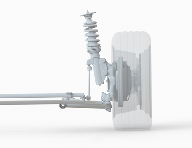
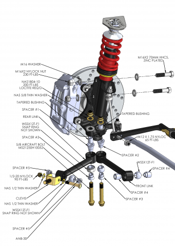
Final product:
-
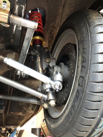
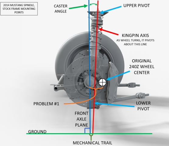
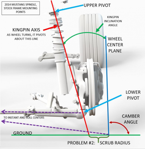
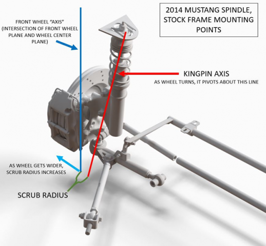
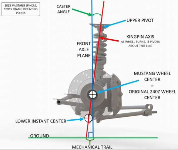
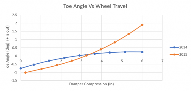
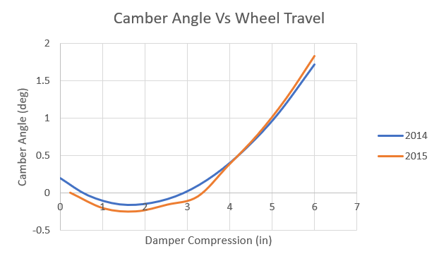
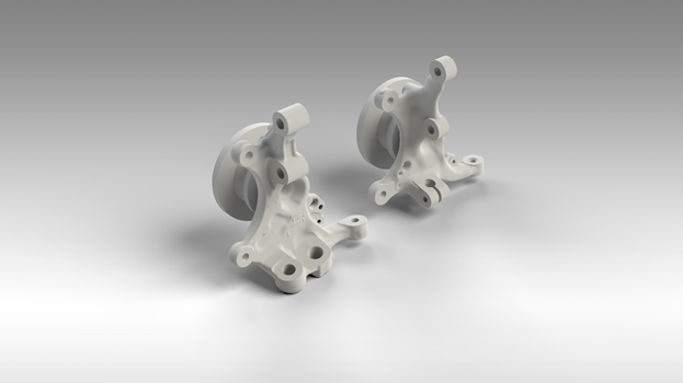
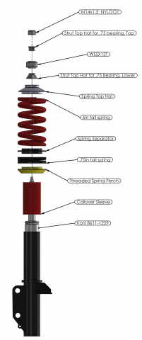
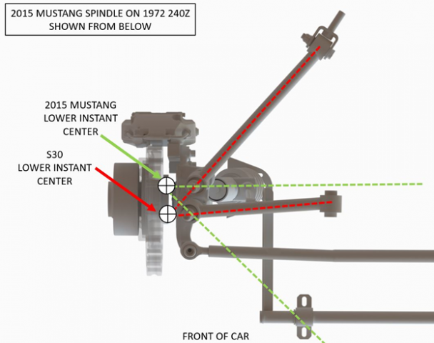
Introduction Hi everyone, my name is Noah and I design all sorts of hotrod suspensions and chassis for a living, and have been using my 240z to play around with some of my more hair-brained ideas. I'm @noahdropkin on instagram if you want to see more of my over-engineered Z parts. I'm putting all this out there because I'm confident that nobody would actually take the time to reverse engineer what I've done here and turn it into a marketable kit, its just far too expensive to produce. You can go take the parts off a wrecked 2015 mustang and hack them up, I promise you it wont work worth a damn. For anyone who really wants one, if you can arrange 5 people to each pay ~$5K for a complete set of double adjustable coilovers and a complete front end suspension kit, then I'll find a way to do a small run. If you want to know why this thing is so expensive, see the exploded view down below. (I spent weeks hunched over a lathe.) I built one more kit for Mr. 280Z-LS3 (he's doing a build thread, go check it out), because having to deliver him a kit was the motivator I needed to actually get the whole thing done, and because it was many long chats with him that got me thinking and sent me down this rabbit hole. Yes, I could've done a double wishbone setup, but that's been done before and has some inherent compromises I wanted to avoid. I recently got the chance to compare the kinematics of this setup to one of the dual wishbone front ends out there for a Z, and was very pleasantly surprised to see how advantageous this is in terms of scrub radius and camber change. Lets dig in: I knew when I picked up my 240Z I'd end up building some sort of specialized suspension setup for it, but I didn't quite know what. I knew I was going to need a new rear end to handle LS power and came across a Ford Super 8.8” (2015+ Mustang Diff) IRS swap kit that seemed to tick all the boxes, and got my hands on one of the first kits. That kit uses a 2014 Mustang front spindle so that the front and rear bolt patterns match, and so that you can use 2014 Mustang front brakes to match the rear. Unfortunately, using a 2014 mustang spindle on a 1972 240z doesn't work out that well for a couple of reasons. The first is that the wheel gets pushed forward in the wheel well the better part of 2 inches. If you compare a 240z front spindle and a 2014 Mustang you can see that the Mustang wheel center is pushed forwards of the kingpin axis, which is the axis which connects the lower ball joint and the coilover mount, and is what the wheel rotates about as the wheel turns. Now, this isn't an unsolvable problem. If you've got fender flares on your car you can mount the flare and cut the fender up so that it doesn't look like the wheel is that far forward, but if you're not using flares you're a bit out of luck. If you were to try pushing the lower ball joint rearwards, either by hacking up the arm or flipping the front control arm bushing around, you'll end up with no caster angle, which means the wheels wont self-center themselves correctly when driving. The second problem is one that all Z's using wide tires with big offsets share, and is exacerbated if you've got fender flares. The scrub radius of the suspension is the distance between the center of the tire contact patch and the point where the kingpin axis intersects the ground. The larger the scrub radius, the harder it is to steer the tire, so small scrub radii are desirable. In order to change the scrub radius of your suspension without moving the tire you need to move either the lower ball joint or the upper shock pivot. In many cases, the brake rotor gets in the way of where you'd want to put the lower ball joint, and nobody wants to cut up their strut tower to move the shock mount drastically. If you could move the lower ball joint out or the shock mount in you'd also increase the kingpin inclination angle, which means you'll have more camber change as you steer the wheel. Now, this isn't great, you want a pretty low kingpin inclination, but often times you have to take what you can get. (For those of you following along at home, we're on page 626 of Milliken and Milliken's Race Car Vehicle Dynamics) So, how do you push the lower ball joint out with a brake rotor in the way? Well that's where the 2015 Mustang spindle comes into play. This spindle uses what's called a "split lower link" where what used to be one lower A-arm with three pivots (which is what the S30 uses, it's just split into two parts) is replaced by two links with two ball joints each. In this setup, the kingpin axis is formed between the upper pivot and the instant center formed by the two lower links (the intersection of the two links). This is shown on the 2015 Mustang spindle below, looking up from the ground. (THIS IS WHERE THE MAGIC HAPPENS) So here's where this gets even trickier. On the 2015+ Mustang the two links go to the front and middle of the car (shown in green), and the S30 has it's two mounts at the middle and rear of the suspension (shown in red). Luckily this can be used to our advantage. Ford wanted to keep the lower instant center in (more or less) the same place as on the 2014 Mustang. By shifting the links around we can push the lower instant center towards the front of the car, bringing the wheel backwards! This gets the center of the wheel right back to where it was in stock S30 suspension, solving the biggest problem with the 2014 spindle. The difficult part in doing this is connecting the linkages to the mustang spindle in ways Ford never intended. The 2015 Mustang uses one link on top and one on the bottom of the knuckle, which helps prevent them crashing into each other. Because the S30 control arm mounts are on an axis parallel to the ground, if you were to mount the two links to the stock frame locations and the stock points on the spindle, you’d have undrivable amounts of camber change. So, in order to adapt two spherical bearings onto the Mustang spindle I machined tapered spacers that are pressed into the spindle, through which two 190ksi 12-point aircraft shank bolts pass through, bolting the whole thing together. The price on these bolts is eye watering. Luckily the spindle can be steered to the stock steering angle before the two links collide, though a hard stop is required on the steering rack to limit travel. The steering arm on the 2015 spindle is rather short, but should be well suited for autocross and track day driving, though it might be a bit twitchy on the highway. The 4° of caster should take care of high-speed stability. Rather than pay someone a fortune to build custom coilovers for this I decided to tackle that myself, using a universal Koni double adjustable strut insert as my starting point. To make life a little bit easier I got in touch with TechnoToyTuning and asked if they would sell me the threaded shock tubes with gland nuts that they use in their coilovers and they were happy to oblige. They also supplied the spring perches and threaded sleeves. For springs I settled on 350lbs/in in the front and 300 lbs/in in the rear, each paired with a tender spring. This nets me roughly 2” of droop travel from ride height and 4” of bump travel. Spring rates were determined based on a target roll gradient of 2.85 °/g, which can be increased to 2.55°/g by use of a 1” dia. 0.065” wall anti-roll bar up front and .75” dia. 0.125” in the rear. Thanks for reading the whole thing! DO NOT TRY THIS AT HOME. Statics: 2014 2015 Kingpin Angle (°) 14 15.61 Caster Angle (°) 3.16 4.05 Scrub Radius (in) 3.79 2.52 Front Roll Center Height (in) 0.9 1.96 Steering Arm (in) 4.2 3.39 Mechanical Trail (in) -0.32 0.379 Wheelbase (in) 92.6 90.9 FVSAL (in) 215 146 2015 Spindle (left) vs 2014 Spindle (right)
-
280Z build w/ LS3 and 2015 Mustang spindles/8.8
D1t replied to 280Z-LS3's topic in Gen III & IV Chevy V8Z Tech Board
For future reference of anyone else doing T56 and the super 8.8, this is where I ended up, but always measure your own driveshaft. -
280Z build w/ LS3 and 2015 Mustang spindles/8.8
D1t replied to 280Z-LS3's topic in Gen III & IV Chevy V8Z Tech Board
Aydin, if you do that your rear u joint won't have any angle on it, which it won't like. Excellent work Joe, hope you had fun with the seam sealer on those front shock towers