

CarJway
-
Posts
227 -
Joined
-
Last visited
Content Type
Profiles
Forums
Blogs
Events
Gallery
Downloads
Store
Posts posted by CarJway
-
-
Sooo, I thought of doing a small write up after I did this today, so this will not be my best write up... Pictures will suffer, but I tried to pull all the information together. I have added some generic pictures, and how to re-wire your car to use an internally regulated alternator. (not my instruction on how to rewire)
First things first... WHY do I need to upgrade?! Well, if you're like me, I now two fuel pumps, two electric cooling fans, blah blah blah... When my car was at idle, I could hear the pumps complaining, and if my fans came on, forget about it. Was it a grounding issue? No, my car has a full painless rewire, and I have more grounds then girls you stalk on instagram.
My initial upgrade was to an 84 maxima alternator. While this put out 60 amps, it definitely did not put out enough amps at idle. I am not sure if this lead to the death of 3 Odyessy batteries, but I will soon find out. On to what you came here for.
My first want here was bolt in, as in no cutting, making a brackets. (I have power steering and didn't want to undo a bunch of stuff) This ruled out the GM alternators, as you have to cut up the stock bracket. I spent a few hours on rock auto searching for all the combinations, amp, ear locations and have come up with the below.
1994 SOHC Nissan Maxima GXE Alternator (i believe this starts in 1991 up to 1995)
1990-1995 Nissan Pathfinder Pulley OR 1990-1995 Nissan D21 Pick up Pulley (I ordered a 1992 pathfinder pulley and i know this works)The Maxima Alternator puts out 90 amps, but at idle put out 58 amps! I looked at the Nissan Quest, and while it puts out 110 amps, it only put out 41 amps. So the clear winner for me here was the Maxima. Plus, it would take no fabrication to "bolt in". (the idle amps may vary, but this is what i found after buying a whole heap of alternators at once)
The Pulley: almost all the higher amp alternators use a ribbed belt, vs a V-belt. After much searching, the best combination was to find, purchase, junk yard the v-belt pulley from a Pathfinder and put that on the 90 amp Maxima alternator.I used an impact to swap the pulleys with a little red loc-tite.
The Wiring: I didn't need to do this due to my Painless harness install, but if you are still stock read the following site! Or search how to swap to a later Datsun alternator for more details on going from an external regulated alternator. (if this applies to you)
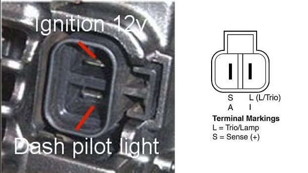
There is now a plug for the Light/Sensing wire. Below is the diagram of the pins for that plug. You can either buy this connector/plug online for a few bucks or use spade connectors. I had bought the plug, and misplaced it, so I used blue female spade connectors.

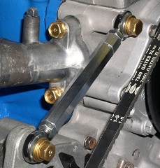
The adjustment bracket: I had already bought one of these adjustable guys yearrsss ago, so it worked well with this. You may be able to use the stock one with slight bending or buy/make one of these adjustable guys. I believe the guys over on Ratsun have a how-to on how to make these, or I could just be mixing that up with another site. Otherwise, just buy one them...
As always with electrical work, ensure you unplug your battery, etc. I take no liability for you setting everything around you on fire, etc.
When upgrading anything electrical, be sure all wire upstream are in good shape. I cannot stress this enough; higher amps is not going to fix an electrical system with hacked up wiring, bad grounds, etc. Be sure everything electrical is in good shape before doing this! -
20910
1 - Medium Short sleeve in Asphalt
1 - Medium Long sleeve in Black
-
Thanks a lot for all the responses guys!
-
Looking to see who has a heater core thats in good shape. Would be great if you knew it didn't leak!
If you know where to get brand new one as well, I'd appreciate the info!
-
I'm writing up a detailed 'How-to' with part numbers, and tons of pictures.
I should have it up later this week.
-
Thanks for all the positive comments guys!
Does rain water collect in it?
It hasn't rained yet, but it shouldn't as their are small slots for my intercooler supports to pass through which should drain it. And while driving down the road I figure most will get sent through the radiator.
I was looking at it, and one thing that might help make the intercooler even more efficient would be to duct the intercooler itself. What I mean by that is you could make a "square tube" that is about the size of the core that proects forward towards the opening in the facia/bumper. Doing that would allow some air around (I do believe the intercooler is smaller than the hole in the bumper, yes?) to go straight to the radiator, but most importantly, the air coming straight from the outside would be boxed in and forced through the 'cooler. I suspect that with your current setting (and pretty much anyone's regular set up), a significant portion of the air that is moving towards the 'cooler gets pushed around by the relative high air pressure zone created in front of the 'cooler. With the "tube" in front that air would have nowhere else to go and would be rammed into the 'cooler (provided the gap between that duct and the 'cooler is minimal).
Finally, one thing you might want to look into is to have some form of an undertray or some kind of spoiler (since your ducting kind of acts as an undetray too by blocking the big gap int he floor) that could help the air flow in a way that would improve cooling. This guys here did some fantastic work on his car (NOT a z car, but the basics are really interesting,and he's got real results). http://www.autospeed.com/cms/article.html?&A=113177
I am actually making exactly that. I am going to block off most of the front with a sheet of ABS, then make the "square tube" you mentioned above, to duct the air into the intercooler/radiator.
Thanks for the link, its good to see some real world data. And for the undertray,I have a 4x8 piece of alumlite. I will be building more of a splitter than an undertray, and will make another thread for when im done with that as well. I will be dropping the splitter a bit, to get it closer to the ground, and heres a link of what I will be going after. http://blog.365racing.net/2012/04/02/evo-front-splitter-part2/
-
There seems to be quite a few posts about ducting the front air dam, but not many have an intercooler. I always saw pictures of a flat sheet going to the core support, and thus making it pretty easy to do. Since I have an oil cooler, and a pretty large intercooler, I knew this wasn't going to be a simple home depot run...
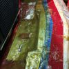
After going back and forth, and not wanting to weld up new end tanks/intercooler piping I was left with the challenge of working around my intercooler. I had a few requirements of ensuring I fully blocked off air from escaping and going directly under the car, and ensuring all the intercooler saw air. I also wanted a small portion of the air to bypass the intercooler, to go straight into the radiator. I came up with the below...
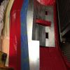
I started with a large 24x24 sheet from home depot, and really only ended up using 2/3rds of it. From the pictures below, you can see my main goal was to keep as much of the metal as I could, and fill in the rest with fiberglass. So what I really made was a skeleton shell out of the metal sheet. I followed the contour of the core support diagonals, and used cardboard to make the angles.
Yes, I know there are drips, and such, but my intercooler almost rests on those areas so I let them be. All the areas which are visible, saw a small coat of bondo. This also ensured that this mated perfectly with my air dam. I let the pictures speak for themselves, and please feel free to reach out with questions.
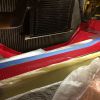
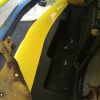
As far as holding this thing in place... You see a stud in the middle of the duct; this pretty much holds it firmly in place. Since I fiberglassed it on the car, it molded/contoured it self in place. I pretty much sat there alone. There were four holes on the core support, which I used plastic push clips to further hold it in place. You see that there are some holes drilled and empty for them.
I am not done with the front end; it will be getting blocked off with a large sheet of ABS. This will further channel the air, but wanted to post small updates as they came. A rear diffusor with pics is also coming as well...
-
Thanks for sharing! Just ordered mine!
Below is the link for the Tri-Bar itself.
-
I second the Black Dragon ones are trash. The car never left my drive way, and they were dry rotted before a year passed.
-
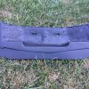
I know its a long shot, but looking to see if anyone is willing to sell their PDK Strut bar.
Picture below for reference.
-
When I purchased RCA's (Bump Steer Spacers) I asked if I was sent 8.8 hardware by mistake. (Instead of 10.9) I was told that in this specific application he would rather have the fastener bend then break. Implying that the 10.9 fastener could possibly break before the 8.8 would bend.
There are other members that have much more fastener knowledge than me, and could further clarify/elaborate on my comment above.
-
Great build! I see you have poly bushing in your Tension Rods... Might want to take a look at the thread below, as there have been some rod failures due to them...
http://forums.hybridz.org/topic/22762-scary-tension-rod-failure/
-
This is awesome... Thanks Derek for putting in all the time, and this might just stop me from putting a F20c into the car!!!
-
I use a Mocal thermostat Sandwich plate with a Setrab 25 row oil cooler. I'm currently making 400whp in an L28 and it seems to hold on the track.
If you don't want to spend as much on a Setrab cooler, check out Earls. It should be around half the price.
Part number for the sandwhich plate; SP1T
-
Give Isky a call, and tell them what your goals, purpose of the car, etc. They will work with you to build something that suits your needs.
-
I've been intending on this swap for months. Glad to see someone else doing it, and taking pictures. Good luck, and keep the thread updated!
-
Have you looked at the Precision Billet 5858? I currently run that turbo with a cam, and if I recall from my last dyno session, boost threshold was around 3300/3400 at 19lbs. No one that has been in my car has ever used the word lag to describe how the car comes back off of boost.
I do see that the power levels you are aiming for are the 300 range, so this might be a little on the larger side. For reference I am running a stock l28et block, making a little under 400 whp. (car is used for road course/driven hard every chance possible) I will try to dig up a dyno plot with boost on it...
-
I am currently running a Spec 3+ with a fidanza flywheel on an L28; my car makes a little under 400 whp, and equal torque. Don't expect the clutch to drive like a honda, but its definitely manageable on the street. I also have no problem daily driving an evo9 with a dual disc clutch through traffic, so use that as a reference for driveabilty comment.
There is nothing more frustrating then being on a dyno/street and your clutch slips. The Spec is a little pricey up front, but gives you room to grow. So, if you don't plan on doing much more than NA turbo, you may look at something else, but we all know how that story goes. I plan on using E85 and being in the mid 400's and fully expect this clutch to hold. I only drive the Z to abuse it, and the clutch has taken everything I have given it.
-
I am looking for the screws/hardware to attached both halfs of the plastic column cover. There should be 4 small narrow screws, and 2 other machine thread type screws. Total of six.
-
Window switch; unless you are controlling the solenoids via a standalone no switch is needed. As you will control this via the ECU. Set the juice to cut off 250-400 rpms before your redline. I give that buffer, for any type inconsistency in what you are using for a trigger. I had the same setup you described (WOT/Arm) and it cost me 2 head gasket jobs. For the small price of a window switch I think its needed.
Placing this in the pipe; since you are boosted, you are going to have to worry about sealing the lines going into the pipe. Vibrations wouldn't be my worry here, but rather sealing everything on boost. As well, placing this in your charge pipe with the bends might not be an issue due to positive pressure in the intake tract, rather than vacuum alone carrying Fuel/Nitrous. I never got into a boosted nitrous setup, but nozzle placement/bends might not be as critical.
BOV; I can see where you're coming from. But if anyone thinks your a ricer, let them see what a 'ricer' L28 is all about... I would probably go with an open to atmosphere to avoid any added complications.
-
My experience with N20; gone through 30+ bottles and sprayed 150-175 wet in my mustang. I made a bunch of mistakes, decent size nitrous back fires, etc.
The key with it, is it is only as safe as you make it. Having the appropriate safety measures like a window rpm safety switch is very important unless you are running this via a standalone. Pressure pure, etc.
I don't think any of the suggestions made for nozzle placement will be optimal. You should have the nozzle 3-6" in front of the throttle plate, with the straightest path possible. Atomization is critical with a wet shot, and placing it behind the throttle plate doesn't seem as this will occur. Paths to runners could separate this process and give unwanted results/performance.
I wouldn't worry about puddling, unless you are running a large 'shot'. Velocity is going to be important to avoid that, and if worried don't spray until the upper RPMS'. In my case, I was spraying 150 above 4k and never ran into any issues. I would run the nozzle in the pipe between the intercooler/throttle body. If you attached a picture we could gauge how large of a 'bend' you have. There are also controllers that will progressively spray via RPM to ensure items like velocity are present.
As for the BOV; having fuel go through the turbo isn't directly an issue, as this is how some blow through setups are. Some will state that the gas drop lets 'can' damage the compressor wheel, but you will have to further research that. I would further look into any residual fuel going through the intercooler. I am not mentioning the N20, as it is an accelerator to the fuel, and why I am only mentioning the fuel. Is there a reason why you cannot vent to the atmosphere and possibly avoid this worry?
Keeping this looking clean should be easy; place both solenoids in a fender and only run the two stainless lines for the nozzle. I hid every aspect of my N20 system. My purge would run under my car, and I would only purge when doing a burn out to keep the noise/puff cloud a secret.
I have only touched on some points to get started and didn't go into full detail but can certainly share all my explosive experiences...
-
I am looking for the pulley that is located at the top of the engine, for the power steering pump. Let me know how much shipped to 20879.
-
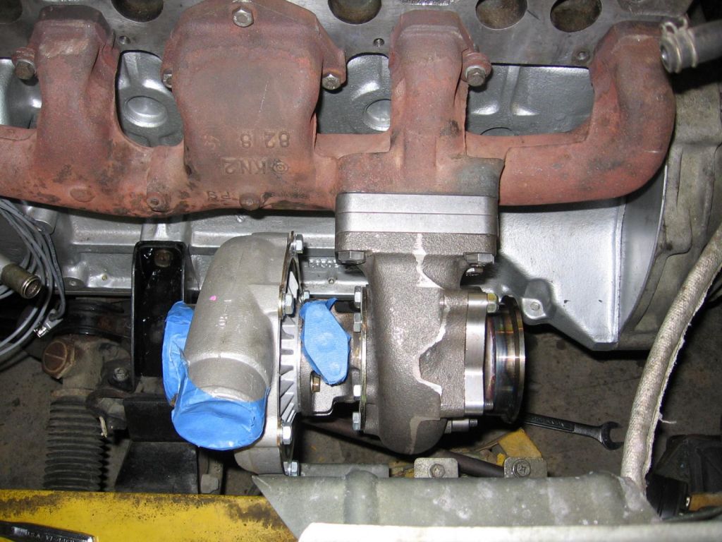
I welded two 3/8" or 1/2" T3 flanges on my manifold to get the clearance I needed.
-
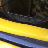
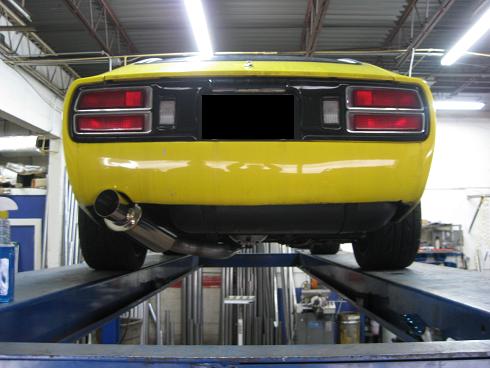
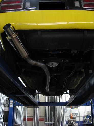
Got this done at Mandrel Bending Solutions in MD. Straight through Vibrant muffler sounds crisp/deep at all RPMs. These pictures are very old so don't mind the dirt/grime on the car.

90 Amp Maxima Alternator Upgrade
in Ignition and Electrical
Posted
BJSZED: how did the swap turn out? Were you able to confirm some of the questions you had when you did it?
Redfogo: I had to use a newer pulley, as mine wasn't a one piece unit, but a two piece pulley. (two halves) I made a video, and get into more of the details there.