
mclark999
-
Posts
104 -
Joined
-
Last visited
Content Type
Profiles
Forums
Blogs
Events
Gallery
Downloads
Store
Posts posted by mclark999
-
-
Thanks and I was prepared to go that route except I had the MM lines already. Ross got back to me and having the install instructions make all the difference. For anyone searching this in the future because of missing instructions:
Modern Motorsports Rear CNC Custom Stainless DOT line install.
The longer line is the passenger side line and goes direct from the caliper to the T fitting junction under your car.
You need one additional 20" long male male metric M10x1.0 Japanese (not Euro) hard line , not included, ~$3 or so and a stocked item at any auto parts shop, this is installed on drivers side into the T junction and then to the shorter supplied braided line and then direct to the caliper. Do not snug down your outer line clamps near edge of inner fenderwell until you have the caliper and brake line all mounted up as you'll find the angle of the brake line/outer clamp will find it's own comfortable geometry and can then be snugged up. The 20" hardline item is not included as it would require a much larger shipping box for which the extra shipping volume etc would incur costs far greater than the cheap and easily available parts costs.
As well, swapping ebrake cables left to right and right to left improves your geometry.
Since it is so hard to get Ross's attention - I've been trying for ages to buy the brake lines from him - can you tell me how long the stainless steel braided lines are that he includes in his kit? I'll just buy the right length ones from Classic Tube.
-
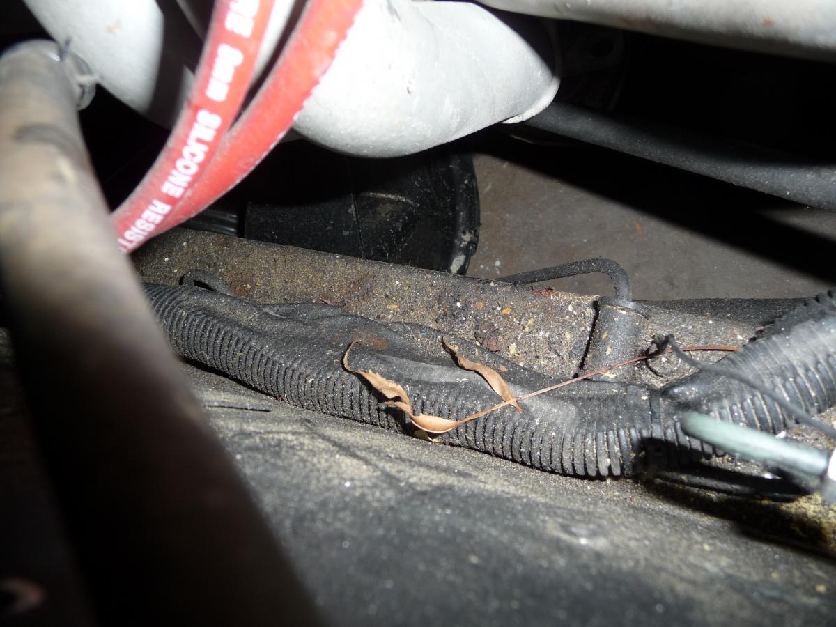
I was starting on installing an aftermarket brake proportioning valve and noticed that the wire loom running down the driver side is all melted. What is a good way to protect the wiring? Does it need to be relocated?

-
Just went out and checked mine. They work with the key off. I drive an 80 280zx though, not an s30.
Makes sense for them to work with the key in the off position though
Another friend just checked and said the same thing. In all the threads on getting turn signals to work, I don't think this particular topic came up. Lots of problems with turn signals not working, hazards not working or both, but not one on hazards not working with key off.
Wiring diagrams are wonderful things. That and neck stretching under a dash. No power at the red/blue wire at the hazard flasher. Have power across the fuse block. Then noticed a 2 inch long red/white wire sticking out of the fuse block with the last half inch bare. Checked it and sure enough its hot. I know the guy I bought the car from was a dufus, but leaving a hot wire bare?
Anyway, what I saw he did was connect a solid blue wire that's only hot when the ignition is on to the red/white wire heading to the hazard flasher unit. I wonder what he was doing and why?
The wiring diagram shows that that red/white wire goes to the instrument panel and become red/blue when it comes out to the flasher. Maybe it feeds the clock and he didn't want the clock to run his battery down? No idea, but I got it fixed.
Thanks for you help. I love this community.
Michael
-
My turn signals and hazard lights weren't working, so I read all the threads I could find and with a replacement hazard switch got both the turn signals and hazard lights working with the ignition on.
Question I have is should the hazards work when the key is off? I have to pass a light and safety inspection to get my Velo Rossa licensed and don't want to get there and find out the hazards have to work with key on or off.
Thanks
Michael
-
I know I could search through the archives, but I also know that technology and products change so I want current advice.
I'm going to be gluing my Velo Rossa tub to my Z next weekend.
What is your opinion on the best fiberglass to steel adhesive? Anything you would definitely tell me to avoid using?
Thanks for your advice,
Michael
-
The link on the very first post doesn't work any more. Could and admin please fix it?
-
Mine has the large round holes on the radiator mount, but no holes on the side/inner fender. There does appear to be a boxlike channel that goes from there all the way to the fresh air boxes above the firewall. Maybe I will get those tubes and cut the necessary holes.
I am kind of liking the vent idea, but it's more work.
-
Fresh Air Vents for Velo Rossa
As I'm getting closer to completing my build, I noticed that the Velo Rossa hood covers up the fresh air vents on the Datsun. I'm looking for suggestions on how to get fresh air into the heating cooling vents.
One idea I have is to run a duct from the front of the car into the air boxes, but that would clutter the engine bay.
Another idea would be to put vents on the hood like the original GTOs had. I'm not a big fan of this. To me it looks like they forgot that the driver needed air and just stuffed some vents on. Kind of ruins the sleekness of the car.
I guess a third option would be to add grilled vents in the hood above the boxes that sit flush with the hood.
The attached pic is vent from an Aston Martin that could look nice.
And it also occurred to me that I could punch a hole through the fender well and up into the air box and take advantage of the side vents behind the front tire.
Anyone else have a thought? Any pictures you can provide would be great.
-
Replica Spyder on sale in ebay.
-
Ultra lightweight V12 Option
Would save over 200 lbs from stock and fit easily.
-
Disadvantage is; more flexible hose means squishier pedal. The flex lines should only be a long as needed for suspension travel and full droop when the car is lifted.
Do you need new hardlines? If so, then check out autozone for nice brake line tubing, pre flared with metric fittings in a variety of lengths.
To sum up your problems;
1. You used MSA factory replacement lines. They have tube-flare fittings on both ends because that is what the factory hoses went to.
2. You spent almost as much on adaptors and shipping as new lines would have cost you.
3. adaptors failed, that is the learning curve working there. Folks with experience would have known better. You have to learn somehow.
4. You are still ignoring what folks have told you by "re-engineering" your hardlines.
You need:
2x ~16" hoses with AN-3 and 3/8"-Banjo ($18 each)
2x Chassis braket adaptors with Metric tube flare to AN-3 ($3 each)
...
I bought some SS lines that have the right fittings on each end, but they are only about 12" long. With the rear tires off, I can raise the suspension high enough that they bind at the top of the range. I would buy some from Ross at Modern Motorsports, but he doesn't seem to be around anymore. Anyone know where I can get longer ones?
-
What a happy sight. Everything renewed and ready for when the struts come back from the welder.
What I ended up doing is bolting the sway bar to the car as usual and then with the end links in place, I put a long piece of pipe on the top and wedged that up in the strut tower where the strut would normally go. Then jacked up the lower control arm which squished the bushings enough to get the nut on.
-
Are you using the bolt, nut and other hardware provided with the new bushings? The poly bushings won't work with the stock link.
Yes, I'm using all the new hardware that came with the end links. I think I will try a combination of compressing the top two bushings with a clamp and jacking the control arm up to squeeze the bottom. I had not thought of that because the repair manual instructs to put the end links on and then clamp the sway bar to the body.
Thanks for the advice.
Michael
-
This project has been one of the more humbling ones for me. What I think will be simple becomes... I'll stop whining and ask the question.
I'm installing Energy Suspension polyurethane end links on the front of my 280z using the stock sway bar. I can't get everything compressed enough to get the nut on the bottom. The poly bushings have a raised portion on them that is supposed to seat inside the holes on the sway bar and the lower control arm. The raised part seems too large in diameter to fit into the sway bar hole and the lca especially. I think that's partly why I can't get the whole thing together.
Please share your experiences in how to get this compressed enough to get the nut on.
Thank you,
Michael
-
Not a big fan of the 3/4" up and 1/4" out because on my car 7/16" up got rid of the bumpsteer. 1/4" out has a minimal effect on camber, but is not really doing much of anything else.
As to how I got the hole straight up, I just laid a square on the table and marked it and then eyeballed it a couple times to be sure it was as close as I could get it. When I did this I found that the rack was 1/8 or 1/4 lower on one side, so the tolerances are not super tight from the factory and it isn't necessary to be down to the .0001 on these.
From the picture above, it looks like you doubled the wall thickness by adding to the outside. Is that right?
Regarding the 7/16" up removing the bumpsteer. Have you talked to others about this? Do you know what the consensus is? I won't be racing, just spirited street driving and trackdays at 80%.
-
Not a big fan of the 3/4" up and 1/4" out because on my car 7/16" up got rid of the bumpsteer. 1/4" out has a minimal effect on camber, but is not really doing much of anything else.
As to how I got the hole straight up, I just laid a square on the table and marked it and then eyeballed it a couple times to be sure it was as close as I could get it. When I did this I found that the rack was 1/8 or 1/4 lower on one side, so the tolerances are not super tight from the factory and it isn't necessary to be down to the .0001 on these.
I will be lowering the car at least 2" using sectioned struts and coilovers. For the Velo Rossa, anything less than this much drop doesn't look very good. Maybe I will slot the crossmember providing me adjustable bump steer. I know some other guys have done this. Thanks for your thoughts. I know you have a lot of experience.
-
Now that I have it all apart I can see that the doublers are needed. The doubler washer looks to be about 50% thicker than the actual crossmember. And without it, the LCA bushings would slop around forward and back.
Time to find a welder buddy.
-
I have just pulled out my front cross member and am getting ready to relocate the LCA pivot point to lessen bumpsteer ala the JTR manual.
In the JTR manual it is recommended that you reinforce the cross member with a "doubler" before you drill the new holes. Is this reinforcement needed? Does it matter which model Z, 240, 260, 280 you are working with?
Additionally, given very little fabrication experience with metal and close tolerances, (I've built homes, but that's very different), what is the best way to measure to get the exact 3/4 up, 1/4" out from the original hole center?
Thanks as always to the brilliant guys who have lead the way and remember, a picture is worth a thousand words.
Michael
-
When relocating the pivot point as described above by making a slot or by using the JTR relocation, is it necessary to reinforce the crossmember by adding a "doubler"? Is this model specific or is the thickness of the front crossmember the same for the 240, 260, and 280?
Additionally, as someone who has done little fabrication, what is the best way to measure for drilling the new hole on each side and getting everything lined up correctly?
Thanks,
Michael
-
Turns out I didn't have to raise the engine at all to get the cross member out. The cross member just drops straight down. I just put a floor jack under the oil pan with a cut to fit sized piece of would between the jack and the pan. Worked perfectly.
Thanks everyone for your ideas.
-
I want to take the front cross member out of the car to reposition the pivot point.
I have a 350 SBC mounted in the Scarab position. Will I need to unfasten the transmission to lift the engine enough to get the crossmember out?
Any problems with me lifting the engine by using a floor jack under the oil pan?
Thanks,
Michael
-
I sent you the wrong parts or the supplier sent me the wrong parts. I'll send you the right parts.
EDIT: Just checked my stock. All the supposed 280Z threaded collars I have are 240Z parts. I just ordered a bunch of the correct parts and I'll overnight them up to you when I get them in my hands. I guess I need to mic them from now on when they come in.
Big sigh of relief. Thanks John. I should have asked you first. Don't need to overnight them. I won't be installing them for at least 2 more weeks.
Michael
-
I am switching to coilovers on my 280Z. I bought a set of 2" inside diameter threaded collars from Beta Motorsport and they won't fit over my 280z struts. The ends of the struts look to be a little mushroomed, maybe from someone overtightening the strut collar.
Any thoughts on how I can get the collar on? Do I dare file the struts a little to provide some clearance? Could I slot the threaded collar so it can expand and go over the strut?
Thanks for your ideas and experience.
Michael
-
The pic of the Alpha nose leaning against the wall reminded me of the difference i mentioned in the nose. Our headlight buckets are longer than the original GTO's as our noses (on all the fiberglass GTO replicas) are flatter across the front.
For comparasin here's overhead view of an Alpha1 nose, the nose on our red car, an original GTO and an original GTO in bare metal being restored an same with paint
Hopefully me hitting you with so many pics is useful to you an others an not seen by the mods as me being a bandwidth hog
Where did you find the picture of the real 250 GTO build? Can you post a link? Any pictures of the chassis without the body on it?


Seat swap list for s30's
in Interior
Posted · Edited by mclark999
clarity
Maybe I am doing my fabrication in the wrong order. I have 350Z manual seats and cut off the seat sliders and welded 2" wide flat steel across side to side. I have them sitting on the stock 280Z rails, but I don't really see how to mark them or spot weld them while they are in the car so I can pull them out and final weld or drill and bolt it all together. How did you guys mark them up to get them aligned right?
Revised this a bit. I can see how to mark the fronts. Maybe I just need to mark them and bolt them together and put them back in to make sure they work and then take them back out and do the rears.
Did anyone slot their holes so they could adjust them a bit before final welding?