moodah
-
Posts
39 -
Joined
-
Last visited
Content Type
Profiles
Forums
Blogs
Events
Gallery
Downloads
Store
Everything posted by moodah
-
Was anybody able to figure this out at all? Im trying to wire in an rb26 tacho out signal to my 280zx.. I can see that the 78 280z tacho wiring is the same as the 280zx.. The tachos both connect to the NEGative pole on the ignition coil. The question i guess is how is the earth to the ignition coil (blue wire) broken? Does it break via a cam in the distributor? Or does the ECU itself break the earth? The ECU could break earth if it has a CAS I guess, but I dont think NA 280zx's and the 78 280z have a CAS. I can't actually tell following wiring diagrams since they all show wiring up to the power transistor / ic unit, but then dont have any more specific details on the internal IC / Distributor wiring. I was thinking that if you were to take apart a relay and remove the switch and kept the coil, you could run a constant 12v through the coil and connect it to earth and the tacho.. You could then use the ecu tacho out to somehow break the earth? I've heard that the tacho supposedly provides a -5v square wave.. Could you use a transistor / mosfet / jfet to switch the relay coil earth on and off to replicate the original ignition system?
-
Yep, i've pulled the rubber boot off the clutch fork and had a peek inside while my dad started it and pushed the clutch lever in and out. Everything appears to be fine in there.. The fork pivots fine on the adjuster and i can see the throwout bearing on the end of the fork moving in and out when the pedal is depressed.
-
Hi All, Looking for a bit of help with this problem... I've finished my build and ive gone to drive my 280zx out of the garage and problem, while the engine is running it will not shift into gear. The clutch appears to still bind whilst the clutch pedal is all the way in. Engine is an RB26 with a Nismo RSR21 flywheel, Nismo RS240 HZ clutch, and Nismo G27 30210-RS245 pressure plate. My clutch master is a new 83 280zx master (should be 15/16 in size) My clutch slave is a new R33 push slave (3/4 , as printed on its side) I've tried adjusted the pedal to have as much throw as possible, no luck. I've tried replacing the slave pin with a longer one, also no luck. Anybody have some input at what the issue is? Im guess right now is a screwed pressure plate??
-
Interesting crossmember djz... Would a certifier allow that? I gave the ear in my tunnel a slight chopping with a reciprocating saw and then a bit of a file, to end up with this. Structural integrity-related thoughts?
-
Great info. Thanks for the link. I am worried now, however, that I will need to cut one of the mounting ears off in the tunnel to let the gearbox sit in its natural position.. This is not good since there are two either side... I may have to weld another ear on? I didnt really want to have to weld anything to the car body.... Does anyone have any ideas?
-
Oh FFS i've posted in wrong forum. Anyone feel free to move to the RB forum... I cant figure out how to delete it.
-
Hi guys, Question regarding the above.. I've recently dropped a 30/26 into my s130 and im having issues with the transmission sitting in the tunnel.. The stock gearbox crossmember ears hit the transmission and its a very tight fit. Im not sure how to align the gearbox correctly down the tunnel, since there is a little bit of horizontal play.. Should I be aiming to have the gearbox pointing to / as close to the diff as possible so there is minimal driveshaft/tailshaft angles on the joints? Any input would be great..
-
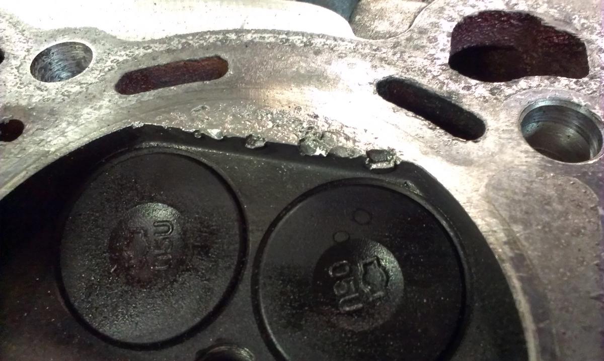
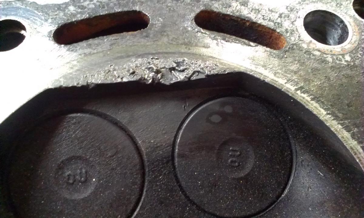
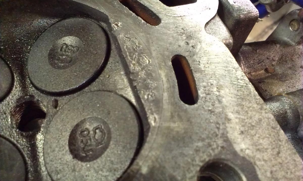
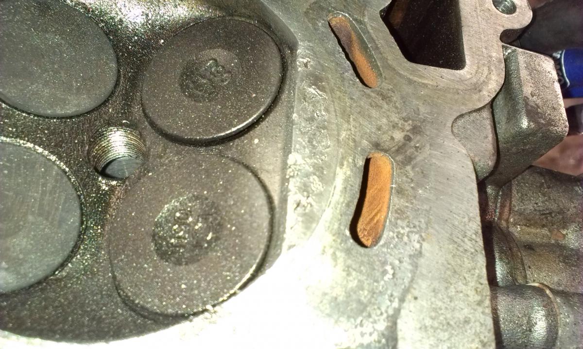
Hmm. It had a full set of iridium Greddy plugs in great condition. Looks to me like there was debris bouncing round in the bores as well.. Couldnt possibly be two cylinders that had electrodes break off.... It does appear that some of the aluminium damage has caused parts to break off though.. id guess this is where the debris has come from.. I wasnt aware detonation could cause this to a head though? No real big deal i guess.. Ill just weld it up and file it back.
-
Really? Are you sure? These pictures are from cylinders 1 & 6. Cylinders 2,3,4 & 5 look absolutely perfect. It is an RB26 head. The engine was completely stock. One of the turbos was seized and missing a few of its ceramic turbine blades. Obviously the boost was jacked up too high. I don't get why this is only on cylinders 1 & 6 though?
-
Hi Guys, Does anyone have any idea what the possible cause of this is?

-
Ahhh SNAP. It would appear the Thermotime switch sensor plug was corroded causing an erratic connection to the ECU.. The ECU wont run the engine without it. I'm sure its intended but I don't know why. I only found the issue since I was stuffing about with the temperature sender to try get the dash to read any signal, bumped the thermotime connection while the engine was running, and it stopped running. Puzzled, I tried starting it again and wiggling the plug.. and it came back on. left it a while, wiggled, dead. Anyone know why its designed this way? Id still go with my original guess that its designed to shut off at certain temp in order to prolong engine/head life..
-
Ive tried with two thermostats. Both of which ive tested in heated pots of water to make sure theyre opening. The RB30 one and a VG30 one. Currently there is NO thermostat in the car and this problem still happens. Every time I drain and fill the coolant system I've been properly bleeding the system through both the bleed screws (screw on top of manifold and next to the water temperature sender + thermotime switch). When I say the ECU shuts off, I mean it appears as if the ECU cuts spark to the engine somehow? I didnt think it was possible though on a motor with distributor ignition system, until I checked the wiring diagram.. The tacho sense wire connects to the [tacho], ignition coil, power transistor and ECU. (probably likely it only uses this wire to check engine RPM, not sure if its actually able to kill the earth to the Ignition coil). After it shuts off I am not able to start it again. There is no spark in any of the leads, yet there is still +12v at the power wire into the ignition coil. I've tried changing different leads from ignition coil to Rotor. I've tried replacing ignition coil. (with spare VG30 one) I've also replaced the Bosch type Rotor cap (carbon button type) about two weeks ago. (button in old one completely disintegrated.) I've cleaned rotor head contacts as well. The fuel pump is always running, I've bypassed the ECU to make 100% sure fuel pressure is not the issue. I did a diagnostic check on the ECU and it told me code 14 (speed sensor circuit). So im wiring it in right now. Im hoping that the ECU will be able to give me some additional info..
-
The engine was sitting in the weather for 3+ years without running. I assume a whole lot of **** was sucked up and lodged into the head. Ill try sticking a garden hose up the heater hose's arse first to see if it can blast any **** out, failing that, Ill see what the local auto parts store has for sale and give it a run through.
-
Hi Guys, Got a quick question; Whats the best way to flush an engine block to clear out any blocked water galleries in the cylinder head? I've dropped in an RB30 and its overheating.. The ECU shuts off before the water temperature sensor in the water outlet reaches operating temperature. I've spent a while troubleshooting this and for the life of me can't get the to get to the correct operating temperature. I've got an ohmmetre plumbed inline with the water temperature sensor in the manifold so I can see what the ohms are currently at, idling the car while it gets hot.
-
Hi, After 1983 280zx warning display harness from the warning display amplifier to the drivers side (AU) kick panel (large black, large white & small white plug under the large blue, large brown and large green plug).... The plug into the warning display amplifier needs to be the flat (not round) pins, and I'm pretty sure its also a 10 pin connector unlike the earlier 8 pin types. Im hoping theres a few people with them sitting round after theyve gotten rid of their warning display. Cheers.
-

[SOLVED] Fresh install rb30 cuts out at 4000 rpm
moodah replied to moodah's topic in Nissan RB Forum
Woot. It was the diagnostic mode. Turned the pot all the way back to the other side started the car and revved to 5k. No issues. Drove down the street and pulled it hard back up under load up to 6k. Such a difference in torque. Cheers for the response iBang. ^^ -
Hi Guys, Took the car out for a test drive yesterday.. RB30E. It cuts out at 4000 rpms... As if the entire ECU shuts off then comes back on just before the engine dies or stays off for a short while completely. The ECU is in diagnostic mode from what I can tell (I never screwed around moving the dial, but its pointing towards 'diagnostic'). Could this be the problem? Would it cut out at 4k to stop engine damage in the event the throttle body got stuck open perhaps? Will check when I get home, but am just pre-empting.. Cheers.
-
Possible RB30 (or any RB) engine mount alternative to mount the engine lower in the stock holes. FJ60 Series Engine Mount.. I have a blog that im using for my 280 at http://280zxproject.blogspot.com/ Im considering trying these FJ60 mounts since they look like theyre about half the height of the VL / R31 mounts. My hood is fouling on the intake manifold, im going to swap it to side mount anyway, but I figure if I can get the engine lower its beneficial all round. Ill have issues with the sump, but I should be able to remove it and do a cut and shut to give more room.. Someone has modified the sump at some point in the past so itd hold more oil anyway. Some pics... Any thoughts? EDIT - (just adding as possible alternatives when I find them..) SIERRA SJ413 87/98 Land Rover V8
-
83 ZX Disc/Handbrake actuator problem
moodah replied to moodah's topic in Trouble Shooting / General Engine
I dont quite get it either... For some reason when the rear caliper was bolted on, pressing the brake pedal in was NOT adjusting the piston as close as possible to the brakepad.. When I pulled off of the caliper, I squeezed the brake pads together onto the rotor with my hand and got my father to step on the brake pedal until the the caliper and piston was sandwiching the pads onto the rotor nice and tight. When the pedal was released the piston then seemed to be aligned correctly. The wheel spun freely but not even a bee's dick could get through the gap between the piston and the brake pad. Before that however.. I had my father pump the brake pedal while it was free off the brake pads - this causes the piston to move out and not retract... The only way i could get it back in was by opening the brake bleed nipple and screwing in the piston (Whilst pushing the ♥♥♥♥ out of the piston). Does this make sense? O_o -
83 ZX Disc/Handbrake actuator problem
moodah replied to moodah's topic in Trouble Shooting / General Engine
Solved.. I've found out that 2 mm is the correct travel the hard way. I put the caliper back together and had screwed the piston all the way in.. I didnt realise you actually have to adjust the piston by distance to the brakepad by using the pedal SLOWLY while the caliper is away from the disc. I have no idea why it doesnt adjust itself up to the brakepads normally while the caliper is on the damn wheel. Thanks for everyones input. -
83 ZX Disc/Handbrake actuator problem
moodah replied to moodah's topic in Trouble Shooting / General Engine
Thanks for the input guys - Ive pulled the piston out of the bore. I can see the piston on the inside has a threaded hole, which the threaded adjusting rod (inside the bore) screws into. Ive measured the amount the threaded rod is moving in and out when i bottom out the lever. It appears to be 2mm (80 thou) of travel. Can anyone please confirm if 2mm of travel is the correct distance the threaded pin should be moving in and out? (cant find this ♥♥♥♥♥♥♥ measurement in the manual anywhere) >< Please help! -
83 ZX Disc/Handbrake actuator problem
moodah replied to moodah's topic in Trouble Shooting / General Engine
As it stands now, I can fully rotate the piston in and out with a set of multigrips, so I know its not frozen. The lever at the back of the caliper that the cable pulls however, I can pull all the way back with my hand, which is not normal. It should be difficult since it has to push the piston out. Now if i'm correct this would mean there must be a cam inside of some kind (maybe part 13 in the pic above??) that pushes out the piston somehow. Could this cam perhaps be the problem? How difficult would it be pulling the brakes apart to make sure all is sound? Im a bit worried about damaging seals and possibly making them worse. -
83 ZX Disc/Handbrake actuator problem
moodah replied to moodah's topic in Trouble Shooting / General Engine
=( From the image below, which part is supposed to rotate? -
G'day Guys, My handbrake is having issues. On the rear left the lever (part the cable connects to) works fine. When i push the lever there is minimal slack, the piston inside is adjusted right and it seems to clamp the caliper as it should. On the rear right however, i can push the lever ALL the way till it bottoms out with my hand. It seems to hardly generate enough force for the caliper to grip the rotor. Ive been driving the car and the car still stops on a dime, however the pedal IS softer than what I remember. My questions are as follows: -What part in the Brake assembly is damaged / worn? -Am I correct in assuming the entire handbrake system is mechanical and doesn't use any hydraulics? -Does this mean my rear brakes should still be working as intended when using the pedal? Any help would be awesome. Cheers.
-
Super-Interesting Wiper Problem
moodah replied to moodah's topic in Trouble Shooting / General Engine
Cheers! Turns out it was just a simple contact issue with the wiper stalk.. over time the copper finger that contacts wasnt fully contacting on the switch... pulled the stalk apart and bent it a little with some longnose pliers so it now gets full contacts and it works like new! Thanks for your insight! -Terry