
Nigel
-
Posts
788 -
Joined
-
Last visited
-
Days Won
3
Content Type
Profiles
Forums
Blogs
Events
Gallery
Downloads
Store
Posts posted by Nigel
-
-
I'm using one of these for a vent valve:
https://fuelsafe.com/tpv6-in-line-pressure-relief-vent-valve/
It's a two way valve that in addition to allowing air to vent in, it also allows excess pressure to vent out (hot day with hot fuel), but without allowing fuel to leak out in the event of a roll-over.
Nigel
-
9 hours ago, guyz said:
Thank you very much Nigel. I now understand how it works. The only thing I'm not 100% certain on are the solenoid ports to use If i blow into port P which is where compressor charge feeds into, that air bleeds thru the side port, if I plug the side port then no pressure gets past the solenoid to port A, which should go to the WG. This leads me to think that the WG should be fed by the side port and not port A. When I apply 12volts to the solenoid, it opens and allows the flow to exit the solenoid via port A(if side port is plugged) This would allow the WG to stay closed, if the solenoid is powered/engaged/open when wired with the controller and would allow the WG to open and spill pressure when the controller hits its preset and then cuts power to the solenoid, thereby allowing it to close and vent out the side port. I hate to seem like I'm belaboring this but I feel like I'm kind of rolling the dice on this part of the install and I don't think that's a great idea.
I don’t have my Mac solenoid in front of me, but assuming it matches the pictures I found online, the ports on the solenoid are labeled with numbers. Looking at the nameplate side of the solenoid, the ports are numbered 2, 3, 1 from left to right, with port 3 being under the nameplate. This translates into the following labeling in the HDi manual:
1: P
2: A
3: R
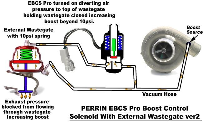
For your application (external WG), the solenoid will be connected exactly as shown on page 9 of the HDi manual. So, port 1(P) will connect to the turbo, and port 2(A) will be connected the upper port on the WG. Port 3(R) is left open. Note that the drawing in the manual could be misinterpreted and read as port 3 being the “P” port, since the arrow does somewhat look like it’s pointing at port 3 (the middle port). Perhaps that’s the source of your confusion, because you said that when you blew into the “P” port when the solenoid was de-energized, it was venting out a side port? If you are blowing into the actual P port (port 1) when de-energized, 1(P) is blocked with no airflow possible, and 2(A) to 3(R) is open. When energized, 3(R) is blocked and 2(A) to 1(P) is open.
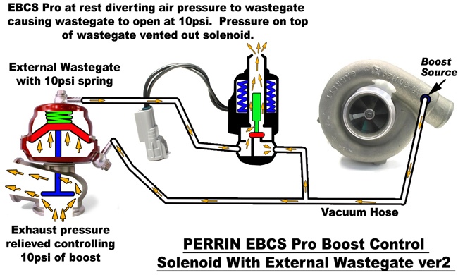
In operation, this means that when the solenoid is energized, boost pressure passes through port 1(P) to port 2(A), applying boost pressure to the top side of the WG and preventing it from opening, which is how boost greater than the WG spring pressure is achieved. When de-energized, the upper port on the WG is vented to atmosphere from port 2(A) to port 3(R), allowing the WG to open. By rapidly shuttling between these two states, boost pressure above the WG spring can be controlled.
As a failsafe, since the de-energized state of the solenoid leaves the upper port on the WG vented to atmosphere (2(A) to 3(R)), the WG spring will then control the boost level, should the solenoid loose power for whatever reason.
-
23 hours ago, guyz said:
- Members
- 0
- 4 posts
- Locationvancouver bc
The waters are cloudy for me when I go to the expanded schematic on page 9 of the online install manual (www.hdimenu.com) where it shows the solenoid output (port A) going to the upper chamber of the wastegate (spring side).
They then show a line connected from the WG lower chamber, below the spring/diaphragm that is being fed by manifold pressure. What that means to me is that when boosting there is essentially an equilibrium of pressures coming at the diaphragm from either side. As I write this it is starting to make sense to me that once the solenoid is triggered by the preset within the controller, it opens and the pressure that is pushing against the top side of the diaphragm and holding the WG closed, then bleeds off via the open and unused solenoid port R, and the WG will then be free to open because of the manifold pressure being exerted against the single, low side of the WG diaphragm chamber. If I've got this correct then some validation from those more experienced here will allow me to carry on accordingly. Thanks in advance
Glad to see my review is being helpful. I'm still running my HDi boost controller all these years later, and it's never given me any grief.
Yes, your interpretation is correct. Here's a couple of pictures that will hopefully explain it better...

-
From 2005
https://forums.hybridz.org/topic/40439-effect-of-fpr-mounting-location-on-afrs-long/
Unfortunately, the links to all the pictures are now dead, and I"m not sure if I even have the originals anymore.
Nigel
-
13 minutes ago, Greeko said:
go to love20bee.com and get reaaaaaaal watanabes.... so glad I did this!
It's nearly a $2000 price difference!!!
-
6 minutes ago, tamo3 said:
Now I need to think about the cover.... Original rubber cover won't fit.
Check out my solution to this, starting with picture 37...
It's held up for going on 10 years now.
Nigel
-
 1
1
-
-
Bleeders are above the inlet point but not high spot on the caliper. I can see how air could be trapped
I looked at a handful of photos of this install. And this is how it showed. Let me get back in the garage this evening and re configure the mounting.
Thanks Nigel for the lead.
IMG_0396.JPGThat definitely won't work with them oriented like that.
You'll probably need to take them off, put a block of wood in the caliper and hold them with the bleeder pointing up while you bleed them. I was never a fan of these SM kits because of this.
Nigel
-
One anomaly I want to bring up is on the when I had it hooked up with the rear port of the master providing pressure for the rear brakes the reservoir would lower the level with each pump of the pedal (stopped lowering after about 3 pumps) but when the pedal was released the fluid would be pushed back up into the reservoir like it was spring loaded in the rear system some how. Is this possibly compressed air?
One of the above posts brings up the low drag design where the boot pulls the piston back. Is this what is causing the reversion?
Any thoughts on how to ID the rear calipers would be great.
I pulled this car from a barn after 20 years of inactivity. Any other things I should check, clean replace etc? Any and all input is appreciated.
Kevin
You may have the rear calipers on the wrong side of the car and they are not being bled properly (trapped air). The bleeder has to be pointing up.
Nigel
-
I know this is a really old thread, but I did want to state that the cooler thermostat did handle most of my heat soak issues, but if I drive a while and then park, then try to go again, it's a bit harder to start. It's nowhere as bad as it used to be. I might try the webbed manifold if I can find one. If not I might try zip tying a plate under my intake to see if that'll fix it.
I was talking to a local club member this past weekend who has a 280ZX turbo with the stock webbed intake manifold. His injector cooling fan just died, and he’s now having hot start issues. So, the webbed manifold doesn’t appear to be the solution.
After everything I’ve tried, the only thing I’ve found that works is to add a delayed off timer to my electric rad fan circuit. The timer keeps the fan circuit energized for X amount of time after the engine is shut off. I currently have it set to 8 minutes, and that appears to be working well. I also have a variable speed controller for my fan, so it only runs as hard as is needed.
I’m using this Velleman time delay relay:
http://www.vellemanusa.com/products/view/?country=us&lang=enu&id=525830
I have a power relay for the fuel injection circuit, and I use the NC contact of that relay to start the delayed off timer when the ignition is switched off.
And I'm using this fan speed controller, with it's own temp sender:
http://www.spal-usa.com/fans/automated/accessories/fanpwmV3.html
I might still try a 70C thermostat. But I drive the car well into the fall, with temperatures in the 0C to 10C range. Not sure how the engine will like that...
Nigel
-
Nigel
Wilwood seems to lack quality control. I bought two 1 inch Wilwood MCs that leaked internally right out of the box. The third Wilwood MC I bought was ok and has been on the car for five years.
I recall another member saying that the Wilwood 1 inch MC he bought had a problem with damage output ports/cones/fittings.
Before I posted, I read through the previous posts and I did find mention of those issues. Very frustrating, particularly with our small sample size. With only a month to go until Z-Con, I really don't have time for this. I'll be livid if the replacement has issues too.
Nigel
-
I started prepping my new Wilwood master cylinder for installation and discovered this...
The mangled cone fitting by itself wouldn't have been a big deal. I could have swapped in the fitting from my 280ZX M/C. But there's no way I'm trusting the cone fitting to seal in the bore of the M/C with those gouges!
I don't have time for this!!!
Nigel
-
No offence intended, but why should we believe you're any more likely to make this happen than the countless others who have started down this path and never delivered?
Let's see a prototype and some realistic pricing first...
Nigel
-
Here is the part info (looked pretty much untouched when bought; said not to have been run since the 80s):
Exactly the same as my 240Z
-
The original one you had in the car is actually a larger 280z booster that a previous owner may have installed at some point.
The smaller booster is actually correct for the stock 240z booster.
http://forums.hybridz.org/topic/99516-240z-vs-260-280-z-pedal-assemblies/?p=933168
Not actually correct. Nissan started making changes to the brake system during 240Z production, including the larger brake booster. I don't know off hand exactly when the changes were implemented, but my '73 240Z has the larger booster, the later master cylinder, and the firewall mounted brake proportioning valve that are found on the 260Z and 280Z. It still had the earlier style drums though.
Nigel
-
OK, well that's weird. I can't see how that could possibly work. Is the rod removable?
Nigel
-
For the flush mounts... how does the adjustment knob thing fit? It looks like it extends into the window....
There is no adjustment knob. You move the mirror directly by hand.
Nigel
-
Do you have to chop up/drill anything on the body/door?
There's a plate that gets riveted to the window frame and screwed to the chrome strip along the top of the door. The mirror gets attached to that plate. So, you have to drill three holes in the window frame and two holes in the chrome strip. No holes in the sheet metal of the door though.
Nigel
-
The flush mount mirrors work well and look good. I used them for several years before switching to JDM wing mirrors.
Nigel
-
Unless 240z's changed transmission mounts, the mount shown in the CX Racing Youtube video is for a 280z unless it is universal. A 240z tunnel is narrower than a 280z, which is why JCI has two different transmission mount styles. Below are the two different mounts between a 240z and a 280z.
'73 240Z's have the later style trans mount.
Nigel
-
Glad to hear there's still interest! I've been so preoccupied with real work that I haven't had time to give much thought to doing another run, but it is on my mind. I'll try to get something going in the near future.
Any more feedback from the first group buy?
Nigel
-
Depending on which lower thermostat housing you have, there should be a couple of available ports. When facing the engine, I used one that was just to the left of the temp sensor for the dash gauge. There was another to the right that I used for the coolant feed to the turbo. They're both British Pipe thread, but you can run a 3/8NPT tap into them and the GM sensor will thread in just fine.
I don't recall which engine I got my lower housing from though. Probably the turbo engine.
Nigel
-
All I see is the side of my car covered in dirt and road debris because the back of the wheel is not enclosed and will allow it to throw stuff all over the side of my car. I guess for a show car it could be cool but not a daily driver.
These offer hardly any less shielding than ZG flares and I don't recall anybody with those complaining about dirt and debris on the side of the car. I certainly didn't notice a significant difference when I added ZG flares and 255 tires. Most of what gets flung up is going to come from down low and mud flaps are about the only way you're going to stop that regardless of tire size or flare design.
Nigel
-
Nigel,
I have the unit from EZ PS. The unit works great and I'm very happy with it. I purchased mine before they offered the speed sensitivity control. I've since tried to purchase it from Roger but unfortunately he has become difficult to get in touch with.
One other thing to watch out for is the angle that the sheering shaft to firewall flange that they used. When I first got the kit, the flange angle was way too shallow and the steering shaft would no way bolt up to the dash. They sent me a new flange that was better but not perfect. I wound up modifying the flange myself to get it to fit.
Other than wishing I had speed sensitivity, I'm very happy with the unit.
Joe
Can you elaborate on why you wish your system had speed sensitivity? What have you noticed in operation that you feel it would help with?
Nigel
-
I intend to get an EPAS kit for my 240Z and at this point there appear to be two clear choices for a 'bolt-in' kit. There's the one sold by EZ Power Steering, and the other sold by Z Power Steering (made by US Autoperformance?). I've gone through all the information offered by the companies, as well as all of the forum posts I can find on-line, and I'm still having a hard time deciding which of the two to buy. On the surface, they're very similar, with both offering manually adjustable assist. The EZ kit is slightly more expensive, but it also includes speed compensated assist, whereas the Z PS kit does not. From a theoretical point of view, I like the idea of speed sensitivity, but I haven't been able to find any real world comparisons to know if it makes a significant difference. Both systems vary assist based on torque, and at speed, less torque is needed, so the assist level should be lower anyway, even without the system adjusting for speed. But ultimately, I'd like something I can set and forget.
Now, I could simply hedge my bets and go with the EZ kit with the speed compensation. The additional cost of the EZ kit isn't enough to tip the favour back to the Z PS kit. However, the Z PS kit does have one unique feature that's keeping it in the running. The steering shaft has an extra universal joint and a ball joint at the firewall. This opens up the possibility of some degree of steering wheel tilt adjustment. This is important to me, because I'm 6'7" tall, and since I sit so far back, I've spaced my steering wheel back a couple of inches so I'm not driving with my arms sticking straight out. However, this also makes the steering wheel higher and the angle I'm now holding the wheel at is putting a strain on my wrists. So, being able to lower the wheel and change the angle slightly might be advantageous.Even with the stock column, there is enough flexibility in the firewall flange that spacers can be inserted between the dash mount to lower the shaft down quite a bit. But the EZ kit appears to have a very rigid firewall flange, and I'm not sure it would be able to flex very much.So, does anyone out there have any hands on experience with EPAS setups with and without speed compensation? Or does anyone with the Z PS kit wish that it had speed compensation? And to anyone with the EZ kit, is the firewall flange as rigid as it looks?Nigel


Silvermine motors electric power steering install for 240Z and 280Z
in Gen III & IV Chevy V8Z Tech Board
Posted
I'm installing this kit in my Z right now, and that explanation for the RPM wire doesn't make sense to me. The White wire that connects to an IGN hot source should serve that purpose, and I bench tested mine with a DC power supply that provides a current draw reading and sure enough, current draw goes to zero when the White wire is disconnected from power. I have seen that some EPAS ECUs require an RPM signal to enable the system so that it's not active when the ignition is on but the engine is off. That way, you can't put a potentially big electrical load on the system when the engine isn't running. However, that doesn't seem to be the case with the Silvermine ECU. The system is enabled and active as soon the White wire is powered. Perhaps the ECU manufacturer disabled that RPM function but left the RPM input wire for whatever reason.
A friend of mine suggested that the RPM input may be a backup of sorts if the speed input is lost, but I tested that and RPM doesn't appear to have any effect on steering effort when there's no speed input.
Has anyone found a conclusive explanation for the function of the RPM wire on this system? I'd prefer to avoid connecting wires that I don't have to.
Nigel