Neveragain55
-
Posts
105 -
Joined
-
Last visited
-
Days Won
1
Content Type
Profiles
Forums
Blogs
Events
Gallery
Downloads
Store
Everything posted by Neveragain55
-
Here’s my analysis: This is what I used which can withstand temperatures up to 1400 degrees. http://www.marine-paint.com/merchant.mvc?Screen=PROD&Product_Code=P20&Category_Code=HiTemp I’m assuming this is what Letitsnow used which can withstand temperatures up to 1300 degrees. http://www.google.com/products/catalog?q=BBQ+Black+Satin+High+Heat+Paint&hl=en&cid=10205419845842435948&ei=z6uDT5q1D8OisAfc5IzoCg&ved=0CAcQ8wIwAA#p Letitsnow has stated that the BBQ paint has help up pretty well thus far and that would fall in line with what the experts told me about POR 20. If the BBQ paint is rated at 1300 and POR 20 is rated at 1400 then I think I’ll be ok…..
-
I thought about that but......... If I have to pull it all apart after a few thousand miles or more, what the hell, lesson learned.
-
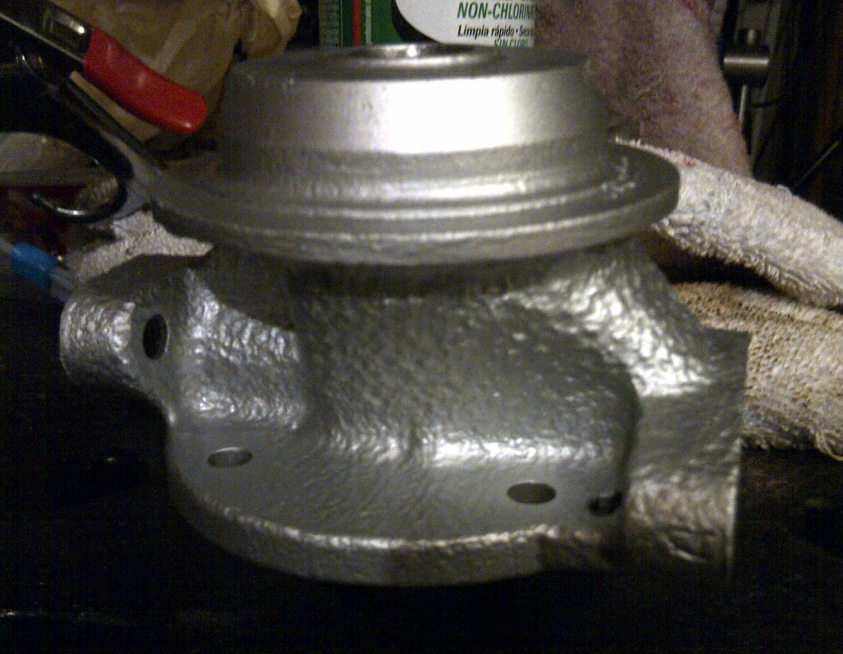
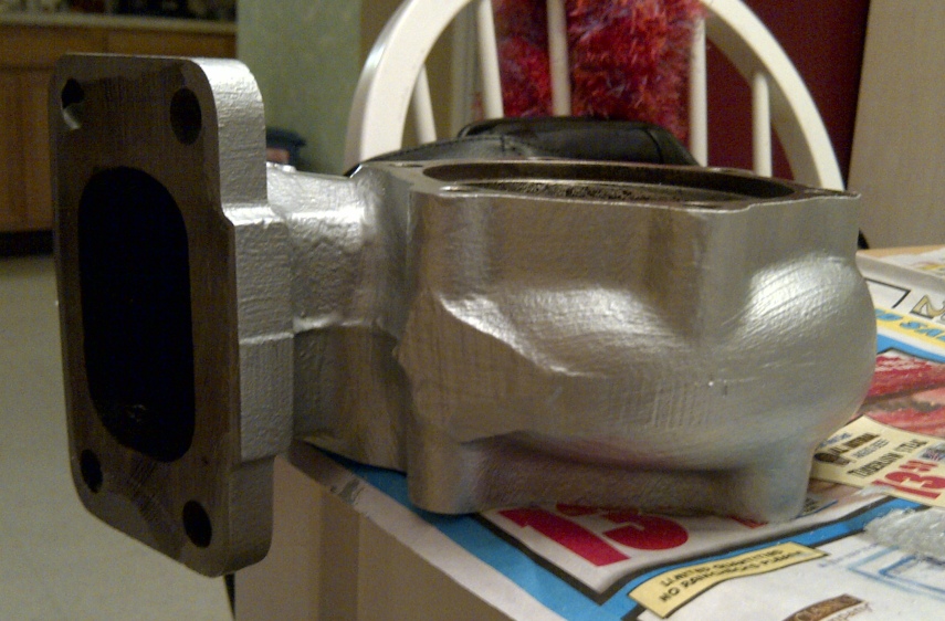
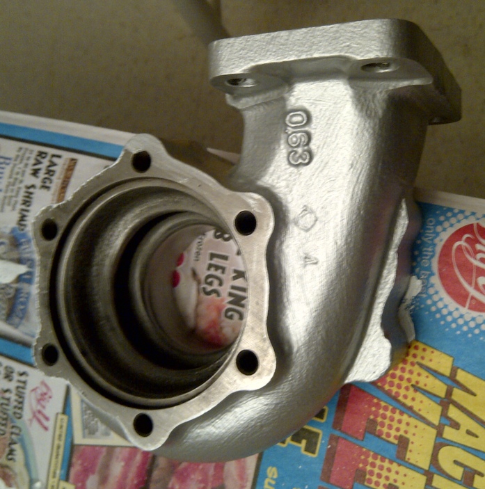
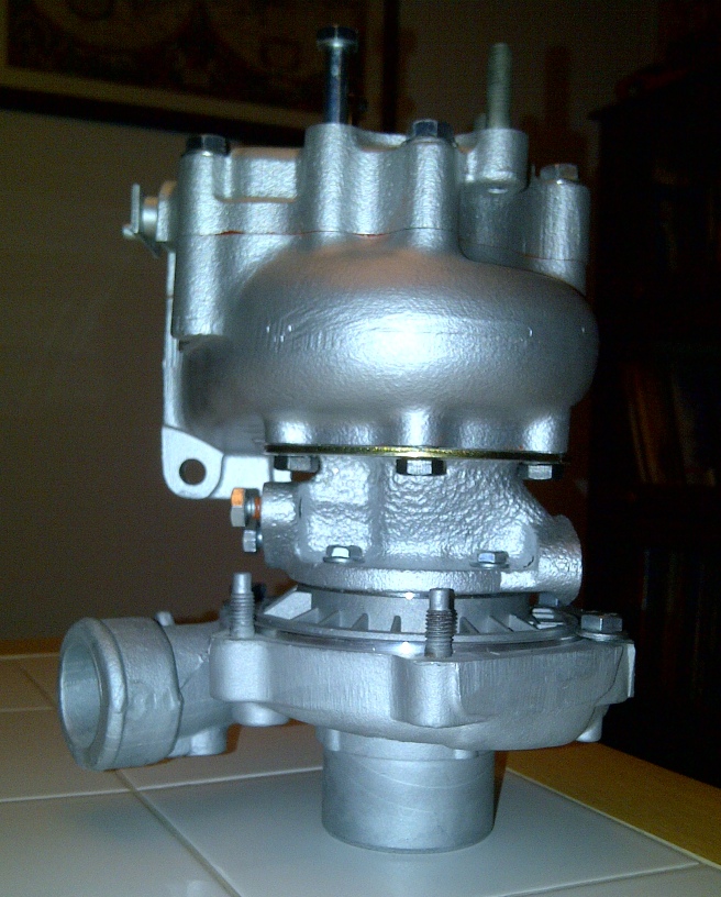
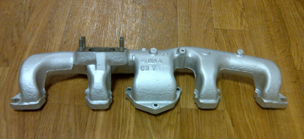
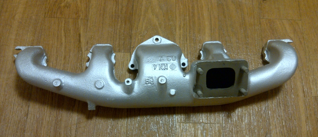
We're gonna find out............. I did a little research and tried to find out what the operating temperatures of the center section, and the tolerances of the POR 20 were before I put it on. Without writing a book on the subject in this small space, suffice it to say "the experts" assured me that the silver high temp POR 20 (which is what I used) will in fact hold up. I also individually baked all the parts (before the new bearings & ring clips went in) in my oven to cure the POR 20 because it will never air dry. You have to cure the stuff onto whatever you applying it to if you want it to stay. I've seen dozens of cats rebuild turbo’s pouring hundreds of dollars into them, just to put all the rusty, ugly components all back together again when they were done. Yes - I realize the rebuilt internals matter more than the appearence, but still................. Why go through all of that and still have an eyesore when you’re done. The worst that will happen if it doesn't hold up is that it will flake up and eventually peel off, but it won't affect the performance at all because it's all on the surface, not the inside. Like I said, we'll see I attached pictures of what it looks like, I put POR 20 on the exhaust manifold as well ....

-
Thanks Dexter72, I'm new to rebuilding Turbo's and I've learned a lot from all of you. It came out really nice. I vapor blasted everything, got all the surface rust off of everything, soaked the parts, cleaned them out all very well, and then I used POR 20 to paint the center and exhaust housings. It's actually looks too good to go back on the car but the last glitch was the turbine shaft. I replaced the original with a new one because I discovered that the old shaft had a slight bend in it. Like I said in the previous post, it spins by hand and by compressed air but it stops sort of quickly once the force to make it spin is gone and I was wondering if that was normal. Now I'm super confident that it is..... Thanks again....
-
Thanks so much Sleeperz, That what I figured because nothing is binding it at all and there is no debris what-so-ever in the housing. Thanks for the quick reply........
-
One last question about the turbo gang and I’m done I promise Everything is put back together to spec and I have used all of the correct parts, seals, and fluids. The turbine does spin freely, the problem I’m having is with the term “spin feely†as it could be vague and subjective. The turbine shaft spins but stops rather suddenly after I spin it by hand or by air. It doesn't stop abrupty, but it doesn't spin much past the point where the force to spin it is gone. It’s not binding at all (that I can tell) but it doesn’t seem to spin and decrease in spinning speed until stopping the way any other rotating object would. (think spinning wheel raised of off ground) Are these turbine shafts designed to be this snug and stop suddenly once the rotating force is off of them, or have I over tightened something causing the shaft not to spin as freely as it should? Keep in mind I am using the original “Journal Bearings†style bearings, and also that I have spun the shaft before and after putting the end nut on with the same results. I’ve also checked to make sure that the compressor wheel isn’t sitting to tightly up against the base, and it’s not. In other words, everything is as it should be, and the shaft does spin, but it seems a little to snug to me and I’ve never put one of these together before so I just wanted to get some feedback from those of you that have. Thanks…..
-
Left-hand (reverse) threaded Turbine Shaft Nut
Neveragain55 replied to Neveragain55's topic in Turbo / Supercharger
All set gang..... Believe it or not I found one at this little mom & pop hardware store a few towns away from me. And it was the 1/4 x 28 size..... Thanks everybody... -
Left-hand (reverse) threaded Turbine Shaft Nut
Neveragain55 replied to Neveragain55's topic in Turbo / Supercharger
Definitely, yes could be. The 28 gauge fit the threads as well as the 9 did. -
Left-hand (reverse) threaded Turbine Shaft Nut
Neveragain55 replied to Neveragain55's topic in Turbo / Supercharger
I want to say M6 x 0.9 If that sounds right.... I measured the thread pitch with a thread gauge and size 9 seem to fit best. The diameter fell inbetween M6 & M7 but leaned towards M6. -
Left-hand (reverse) threaded Turbine Shaft Nut
Neveragain55 replied to Neveragain55's topic in Turbo / Supercharger
I actually did and I'm waiting to hear back from them.............. I'm just anxious and admittedly so, I'm jumping the gun. I don't think they'll have one though because it was an eBay item, and I think all these guys sell are the turbine shafts. We'll see..... -
I love what you’ve done with your manifold and I have a couple of questions. I plan on basically doing the same thing but I was actually planning on eliminating a few more holes than you. I’ve attached a picture of your manifold and a template of what I’m thinking of doing. Everything circled in red in my template is what I plan or hacking off or sanding all the way down and filling in. Everything circled in black (which isn’t much) is what I plan on keeping. Please tell me if I can do this or if I need to keep anything else open. I don’t plan on running any emissions as I don’t have to worry about that stuff in my state. Thanks…….
-
Ok gang, I had to replace the original T3 turbine shaft out of my turbo because after further inspection I found it to have a slight bend (must have happened when I separated the turbo) The new shaft is perfect except for the fact that it takes a a left-hand or (reverse) threaded nut (no, it didn't come with a new one) and the original turbine shaft had a standard right-hand turning nut. I have scoured the internet and driven around to many hardware stores and I cannot find any small metric left-hand nuts anywhere. A little guidance here would really be appreciated…………..
-
Sorry to hear about the vibration issues. I have a 1989 BMW 635CSI that has about 270.000 miles and she's starting to give me vibrating issues as well because BMW's incorporate a guibo coupling between the driveshaft and the transmission mounting flange. Once the guibo's go bad there's a lot of slop and play and the drive shaft vibrates in the lower gears until you get up to cruising speed where she smooths out. I would imagine any driveshaft rebuilding shop that does nothing but fabricate and make custom driveshafts would be able to correctly balance a driveshaft. Good Luck with it....
-
Thanks Trevor...................
-
Can you remember if they cut the shaft in the middle or at the end? That seems to be the sticky point converting the T-5 drive shafts.
-
Is this a Garrett Airesearch Turbo
Neveragain55 replied to Neveragain55's topic in Turbo / Supercharger
Getting a rebuild kit for these turbos is crazy easy but after my experience, I would only get a rebuild kit from either Treadstone down in Miami, or G-Pop Shop. Also make sure you inquire about the dynamic seal for the backing plate opposed to the original one because the aftermarket backing plates are only designed for the dynamic seal. Ask me how I know.............. They're both on the internet: http://www.treadstoneperformance.com/product.phtml?p=134&cat_key=53&prodname=Garrett+Turbocharger+Turbo+Rebuild+Kit http://gpopshop.com/rebuild-kits/?gclid=CIDb7oPqrKwCFYHu7Qod31j-Hw -
Thanks...........
-
Thanks a million Cannonball89.... I'll definitely give them a shout when I'm ready for that stage of the project. I'm trying to keep my head above water just getting the engine back together
-
We gotta stop meeting like this Clive................ This is the shaft you sold to me (Dennis) along with the engine and tranny a while back.... Everything I've read on all the Z forums say the same thing. The drive shaft that comes from the S130 models with the T5 manual tranny have to be shortened 2 inches to fit underneath the 1st generation cars. I'd love to be able to just bolt the driveshaft up and go but apparently you have to do some fabricating to make it fit. Check with your gurus and please let me know if there's a work-a-round to this costly fix. Thanks...
-
Even though driveline work is a bit down the road for me in this project, I’d like to get some advice and tips early on driveshaft fabrication. I’m doing the typical L28ET swap into a 1st generation Z (82 Turbo & 5 speed tranny into a 77 280Z) to be specific. I’ve already read all the write ups describing how this is done and I’m aware of what needs to be cut, shortened, moved, shifted, welded, and all the other happy stuff that goes along with making everything fit. My specific question is: if any of you know of a qualified driveshaft fabrication shop that can shorten the T5 driveshaft to make it fit underneath my 77 280Z, and I'd still have enough money left over to buy a chocolate bar I’m keeping the original rear differential and I’m not making a 500 horsepower monster that would require the driveshaft to hold up to Herculean punishment. I’m in the New England area (CT) and I need to find a good shop (yes I’ve looked) that can perform this fabrication, or if any of you know of someone that already has a shortened T5 driveshaft that would fit, that’s for sale. Thanks Gang………..
-
This particular turbo is the original one that came with the car back in 1982. It's your typical stock Nissan/Garrett Airesearch T3. I've seen the adjustable actuator arms as well and they would help me in terms of "length" But I do still not understand how the different "PSI" ratings affect everything and if it's safe to use a higher PSI rated actuator.
-
Ok Gang, I’m getting ready to finally get the last part for my turbo that will complete the rebuild which is the wastegate actuator. I’ve seen all the ones on eBay, Treadstone, and ATP Turbo and I know what dimensions & type I need. The problem is admittedly, I’m not very astute with the whole “PSI†thing. Meaning the original actuator was a 45º - 6 ¾ in length – 6.3mm hole - 7 psi unit. Everything I’ve seen has two or three of the requirements I’ve just listed but not all four. I need an actuator that has the 45º angle in relation to the mounting bolts – I need for the actual arm to be at least 6 ¾ inch in length – I need the hole at the end of that arm to have a hole diameter of 6.3mm – and I need for it to be a 7psi unit. Here’s where I’m fuzzy, I keep seeing actuators that are advertised as: “crack†at 7 psi and fully open at 10, 15 or 18 psi. Or I’ll see units that say they “crack†at 3 psi and fully open at 7, 10, or 15 psi. What the heck does all that mean, and if I got one of the units that doesn’t fully open until it reaches 10 or 15 psi would that hurt my turbo? (being that the actuator that came off of it was a 7 psi unit) As always, thanks in advance…..
-
Fantastic addvice dude..... Seriously thanks. I'll definitely look into all of that, it all sounds like life-savers. Thanks....
-
I'm with you on the welding jazz Billseph........... The last time I welded anything was about 25 year ago at Apex Tech in NY when I was learning how to do body work. I was pretty good but: (A.) I haven't welded in a very long time, (B.) I've never welded Aluminum and from what I've heard over the years it's presumably very hard to weld, (C.) I don't have any welding equipment. I was going to buy one of those portable welding set-ups that Home Depot sells and experiment because I really need to get back into the art of welding if I plan on doing most of the restoration of my Z myself. I never even thought about using the J.B. Weld, and I have used it on other things and it holds together great. If you get the green light from the guru's in here to use it then I think I'm going to try it as well............. We'll see....
-
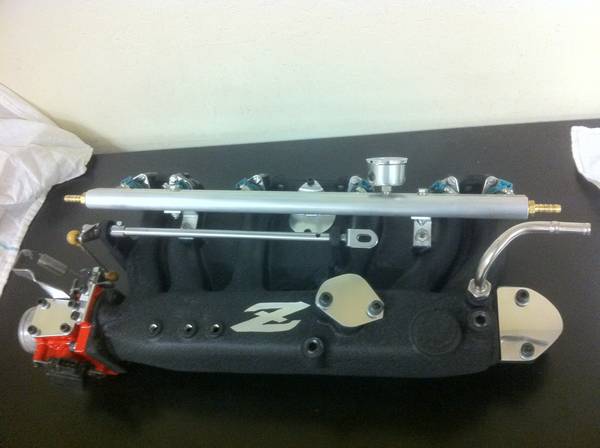
I appreciate all the input guys, and all of it helps tremendously…………….. I’ve attached a picture of what I’m looking to mimic. I basically want to take my intake, hack, cut, grind, and smooth out the surface to resemble the intake that you see here: Once I get it to resemble the image above, the plan is to use one of those Palnet fuel rails or something very similar to give the engine a very 'clean" look. This one obviously doesn't have the webbing like mine, but you get the idea. It's nice to know that we can eliminate all of those things off the intakes and still use them.