LT1-280z
-
Posts
67 -
Joined
-
Last visited
Content Type
Profiles
Forums
Blogs
Events
Gallery
Downloads
Store
Everything posted by LT1-280z
-
Jon, I was a little apprehensive doing this but since I had a spare and the drive line angle was out of whack, why not try? I followed a very specific process to weld this involving preheating to a specific temperature, interpass temperatures and controlled cooling by burying in perlite. Messer states MG600 is designed for this (not cheap stuff). I guess I'll see what happens over time. I've beaten on it for two months with no signs of trouble yet, Yes I also have a Ron Tyler inspired front mount. Pop, The back is raised 7/8". when I installed my LT1 I naively ignored the drive line angles and mounted it as low and as far back as I could. 7/8" up in the rear and 1/2" down at the nose was what was need to bring it to less than .5 deg misalignment and 2 deg driveshaft operating angle.
-
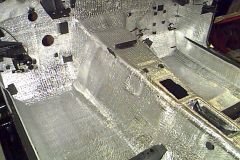
Just thought I'd share a picture of a mustache bar I sectioned to raise the rear of a R200 7/8". Notice the "Z" shape cut lines. I also lowered the nose 1/2" using a RT style mount. The MG600 TIG rod I used is intended for welding this type steel. It really set my drive line angles right.
-
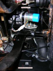
Question about mounting my LT1 PCM
LT1-280z replied to dat240zg's topic in Gen I & II Chevy V8 Tech Board
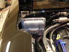
Bartman, Seemed like the logical place after the battery was exiled to the rear. Interesting air box on yours. I like the shark dental work! -
Question about mounting my LT1 PCM
LT1-280z replied to dat240zg's topic in Gen I & II Chevy V8 Tech Board
http://picasaweb.google.com/280z28/280z28/photo#5128426966644874226 -
-
Need more vacuum for power brakes
LT1-280z replied to HICKL's topic in Gen I & II Chevy V8 Tech Board
You could try a restricting orifice in the line to slow down the re-filling of the can. -
While you're under there check that pesky front diff mount. You mentioned the vibration happened under load, there is no load on jack stands. Good news is your driveshaft is probably not out of balance.
-
I just went through this with mine, turned out to be the drive-line angle. For me it turned up only after I started to really get on it. Odd that it was OK for you until now, could your front diff mount be shot?
-
I had the same question myself, not trusting so called authorities, I personally tested this with a piece of clear tube with a piece of string inside to show the flow direction. The picture is incorrect. It flows the other way, out of the lower fitting and returns to the upper. Also if you have one, the connection for oil cooler flows out of the water pump.
-
All better, amazing results when you find a place that can actually build a driveshaft.
-
I'm near Poughkeepsie.
-
Late model LT1 - T56 is the way I went, very happy with it.
-
Pros and Cons of '94-97 LT1 + T56
LT1-280z replied to sstallings's topic in Gen I & II Chevy V8 Tech Board
Greg, Thanks for checking out my Z pics and kind words. If you were to go with CableX or the JTR mod the VSS is retained so you would be totally fine. (run the CableX off the PCM not the sensor) Personally, I didn't want to machine my trans or deal with running a cable. I have seen other V8Z's with older 4 speeds with the cable melted by exhaust heat or just run with too tight a bend causing erratic needle movement. I didn’t even think about the turn signal, high beam and brake indicators, loosing those wouldn’t sit well with me. The concept for my Z project was the car should appear unmodified (there are subtle changes only a true Z enthusiast would catch), all systems should function as if they were still in their respective vehicles and the car should drive like it was factory made that way. Good news for keeping the stock gauges is calibrating the Z tach is a no brainer. Thinking about the speedo drive motor; it actually doesn’t need to have a tach you could go an alternate method of having some sort of rpm sensor in the system – WAIT I’ve got it! You could use the external VSS sensor from JTR to feed back the cable speed to the controller. With this you could use just about any R/C car/airplane/boat drive motor and with the higher torque of the R/C motors you could probably do a direct drive. This would make all the parts readily available, could be on to something here. -
I think a 1350 would be way overkill for my application - I only ever plan to make 350HP if that. I found a place that can build a 1310 driveshaft and high speed ballance a with the nissan adaptor flange in place! http://www.pstds.com/
-
Thanks anyway, Mark Williams Corp offers nothing for the Z or the 1310 universals the JTR adapter uses. Too bad really nice stuff.
-
Pros and Cons of '94-97 LT1 + T56
LT1-280z replied to sstallings's topic in Gen I & II Chevy V8 Tech Board
Greg, The one from Abbot looks the same as TCI's, Abbot is probably OEM. Here's the beginings: $300 may not seem to bad. This took me months to come up with, I took it on as a challange - more brain than sense I guess. Maybe I could make kits for the electronics part. First off you will need a motor with tach leads. I found mine at www.meci.com it’s a surplus motor from a very old 8” floppy drive. It was $3.00, its surplus so they don’t have them all the time. Then I used 1/8” aluminum plate, a slot car axle and bushing to make the drive housing for the 2:1 ratio belt drive. I sourced the pulleys and belt from www.sdp-si.com. Then I just cut down the stock cable to mount the drive unit between the clutch and brake pedals (see picture). I kept the cable as straight as possible to avoid any binding since the motor is pretty small. For the electronics, I used two LM2907 frequency to voltage converters http://www.national.com/mpf/LM/LM2907.html one to read the pulse from the PCM and one to read the tach from the motor. Then used the built in comparator to control the charging of a capacitor whose voltage controls the PWM output of a DRV101 PWM driver http://focus.ti.com/docs/prod/folders/print/drv101.html for the motor speed. Since the motor I used is small I was able to drive it directly, a larger motor might need a dedicated driver stage. The only other part is a enable delay (555 timer) of a few seconds to allow the capacitor to charge up before letting the motor turn on since the voltage across the capacitor is inversely proportional to the speed (higher voltage lower speed) the speedo would jump when you powered up. Calibration is done by adjusting the voltage output of the first LM2907 using small tool I built that has a 60Hz pulse (draw down to ground – the same as the PCM). The 95 Camaro has a 4000 pulse per mile output so 60 Hz = 54 MPH. Set in this way all the settings for tire size and gear ratios in the PCM are accurate. I don’t have the PC artwork in a usable form right now. The one in my car is definitely v1.0 but works quite well. -
Thanks Terry, Yes I'm sure its not wheel balance. I have the rear up on blocks and no wheels and I can make it happen. I'm going to see if I can do the hose clamp trick - so far I was able to make it worse! - maybe I can make it go away. I think I may just have a poorly done balance job - not going back to that shop, the guy really scared me - tried to tell me electric motor RPMs are different than engine RPMs. I'm pretty sure I have the flange tightened properly - I got everything snug before I tightened it up. If the JTR flange on a properly done driveshaft has been good for others that’s good enough for me. I'm thinking of just having a real shaft made at one of the reputable racing supply places (Dynatec, Denny's or someplace recommended here )
-
Pros and Cons of '94-97 LT1 + T56
LT1-280z replied to sstallings's topic in Gen I & II Chevy V8 Tech Board
Steve, If you want to use your stock speedo you could get one of these: http://www.tciauto.com/Products/Electronics/ Speedometer Control Unit (SCU) They're a bit pricey. I made my own - the hardest part is sourcing a drive motor. If you are into electronics I can share the gory details. http://album.hybridz.org/showphoto.php?photo=17063&size=big&cat=500 -
-
I’m having a driveline vibration problem with my LT1 T56 280Z. I did have a pinion alignment issue which I corrected using the laser methods posted here (thank you all) and now have pinion to trans alignment of less than 1 deg and a driveshaft angle of about 2 deg. This cleared up the vibration under load completely. As I continue my testing I discovered I have what feels like driveshaft vibration at about 4500 to 5000 rpm (driveshaft not engine rpm). It is not related to load, just speed. Does anyone know of a driveshaft shop that can high speed balance a driveshaft with an R200 pinion flange? The places I’ve found ether don’t have the fixture for the R200 flange or can’t do high speed. Some have offered to balance it without the flange but as the guy at Denny’s Driveshafts said, “that would be like balancing your wheels then mounting your tiresâ€. My driveshaft is the stock 95 Camaro cut down with the JTR adaptor. The place that did the work can’t high speed balance. Any help is appreciated.
-
 Thanks!
 -
-
-
-