djwarner
-
Posts
111 -
Joined
-
Last visited
Content Type
Profiles
Forums
Blogs
Events
Gallery
Downloads
Store
Everything posted by djwarner
-
Autocross and oil pressure... impending doom??
djwarner replied to shuttlefever's topic in S130 Series - 280ZX
Fantastic Shuttlefever! Good to see logic and persistence solving a trouble. -
Autocross and oil pressure... impending doom??
djwarner replied to shuttlefever's topic in S130 Series - 280ZX
Ok, yes, you do seem to have a real problem. If the relief valve is sticking, you would see the pressure drop off you describe. Since you added a second, mechanical gauge, this eliminates the sensor circuit. Since oil starvation is also a potential problem, you might want to consider pulling the oil pan at the same time. Who know what you might find there after 40 years. Sludge might have filled the baffle area or partially blocked your pickup screen. -
Autocross and oil pressure... impending doom??
djwarner replied to shuttlefever's topic in S130 Series - 280ZX
Tony, No disagreements here. "Constant Displacement" is a design term and, of course, volume pumped varies with rpm. What you are describing would occur under two circumstances. One, when under high g turning when oil is sloshed to one side exposing the air to the pickup tube. Baffles are usually added to the sump to minimize this. In this case, oil pressure should return as g loads are reduced. Two, if the oil return to the sump is delayed, the sump can be pumped out. The delay can be caused by a clogged return channel or by poor design when pumped oil volume exceeds the oil returned through the gravity fed channels. Obviously, increasing the pump volume can cause the second condition if a marginal return path isn't also modified. Turbochargers rely on oil flow as a coolant for the bearings and seals. A high volume of oil flow is required because of the high heat of the exhaust side. The small channels inside the turbo and high temperatures make them susceptible to clogging when oil sludges up. I mention this because a company I worked for made the waste gates and control actuators and seals for AirResearch during the 70's and I became intimately aware of the various failure modes. It was common for car companies to under engineer for this higher oil volume requirement. Turbos had their own return lines it was assumed that pressures would not build up. As the turbos sludged up, pressures would increase, causing higher flows to the cylinder heads and more oil retained there. It was critical for owners of these turbo'ed engines observe severe service change oil intervals. -
Autocross and oil pressure... impending doom??
djwarner replied to shuttlefever's topic in S130 Series - 280ZX
Shuttlefever, What viscosity oil are you running? Oil pumps are known as a constant displacement pump. That is, for each revolution of the pump, it wants to push out the same number of cc's of oil. This type of pump will generate whatever pressure needed to push out the design volume. What limits the pressure is leakage around the seals and close clearances in the pump body. Pressure continues to build until the various paths for oil flow accept the requisite volume. This is why these pumps come with pressure relief valves. So what determines the pressure required? Size of the oil galleys, clearance of the bearings, viscosity of the oil, temperature that modifies the oil's viscosity, pressure relief valves, and leak paths. The pump is content to generate whatever pressure required to deliver its design volume, even 0 psi. Your last post expresses the concern that the pressure relief valve may be sticking open, however you describe exactly what would happen when the oil thins from rising temperatures. At normal loads oil temperature is near the coolant temperature of 180 degrees. SAE 30 weight oil at 180 degrees is 14 centipoise, SAE 40 measure about 21 centipoise. As you exercise your engine, cylinder blocks, heads, and oil temperatures rise and the oil thins. At 240 degrees, SAE 30 thins to 6 Centipoise and SAE 40 thins to about 8.5 Centipoise. As the Centipoise drops, the resistance to oil flow through the various passages drops and thus the required oil pressure drops. If you pull over and let the engine idle, it will take quite a while to dissipate the heat stored in the engine block, heads, oil, etc. As the engine cools, oil pressure slowly builds. I suggest you get a non contact thermometer from Harbor Freight and watch to see if oil pressure recovery matches the drop in the engine block temperature. -
Everyone has focused on the lifters. I have the same problem with a L24. These are overhead cam engines without lifters. Initially, I thought I had a rod knock until I took it to the local long-time Z guru. He noted that if it doesn't get worse on acceleration, it isn't rod knock. He quickly pointed out that it is the timing chain tensioner. The tensioner is held in place with a spring and adds oil pressure to keep the slop to a minimum. As the tensioner wears and its spring tires, slop allows the chain to rattle until oil pressure builds. I noted the price of a chain tensioner, gaskets and oil seal are minimal and he noted that the labor is not. Suggested I let it go until overhaul. Said he'd seen engines go over 250K with the problem and no consequences. Since then I've put another 6K on my 175K engine, with no noticeable affect.
-
stupid stock coolant temp gauge not working anymore!
djwarner replied to redzedturbo's topic in S130 Series - 280ZX
The oil pressure gauge and temperature gauge share the same power supply. If your oil pressure gauge is working, the problem is almost certainly at the sensor or the wiring to the gauge. -
Autocross and oil pressure... impending doom??
djwarner replied to shuttlefever's topic in S130 Series - 280ZX
The oil pressure sender has two modes of functioning depending on whether it feeds a gauge or a low pressure light. Below a certain pressure, it stops reading a resistance and simply shorts to ground. Shorting to ground is a signal to illuminate an idiot light. After a long hot run, oil viscosity may become so low that oil flow freely through the galleys with little or no pressure. Whamo, the sender shifts into idiot light mode. Our engines were designed in a different era when bearing lubrication was based on flow rather than pressure. If you look at the pressure specification, it is measured at 2500 rpm, not idle. -
Anyone ordered from www.nissanpartszone.com ever or lately?
djwarner replied to motomanmike's topic in Non Tech Board
I tried ordering a part when they said it was available, later declined the order when they could not get it. If your part number shows up on Nissan's system, they will say they can get it, only later do you find that the part is NLA from Nissan. If you check around their website, you will find they have similar sites for Hyundai, Honda, Ford, etc. I would classify them as an Etail aggregator much the same as Drudge is a news aggregator. -
Hi Ben, Been following your efforts. As mentioned on the other site, bearing clearance should be 0.0015 to 0.0026(difference in the diameters) so this indicates the rear tower is at least 0.001 out of position. For grins and giggles, you could try adding a 0.001 piece of shim stock under the drivers side of the tower. Then see if the prussian blue pattern changes. I measured some standard weight aluminum foil from the local supermarket and it was close to 0.001" thick so you wouldn't have to invest in special shim stock for this experiment..
-
I don't think the OP ever had his question answered, namely why use a relatively blunt nose on an airfoil. Comparing two airfoils, one with a sharp nose and a similar one with a blunt nose, in a windtunnel at varying angles of attack, you will find the slope of the CL is much steeper in the sharp nosed airfoil. So as you decrease the angle of attack, the sharper nosed foil will suddenly go from more than enough lift to just enough to very little to negative lift very rapidly. This is an unattractive trait in a general purpose aircraft - more useful in a fighter jet though. For general aviation a blunter nose does develop a stagnation zone near the leading edge. As the angle of attack varies, the stagnation zone can shift up or down the gently curving leading edge helping to maintain smoother flow and better lift over a wide range of angles of attack. So the blunt nose is preferred for lift purposes - not drag. The other half of his question asked why not a needle shape to reduce drag. You need to consider the what is takes to maintain laminar flow over the surface. The flow immediately above a solid surface is actually traveling at almost the same speed as the surface. This is caused by friction with the surface. As you move away from the surface, the air is not slowed down as much, Go farther and the air is hardly slowed at all. The change in velocity as distance from the surface increases is a shearing stress. The longer the shearing action occurs, the more likely the laminar flow will turn turbulent with resulting increas in drag. So long straight body lines are apt to induce turbulent flow and higher drags. The longer the shape is exposed to turbulent flow, the higher drag will be. So as general design guideline, delay the transistion from laminar to turbulent and after that minimize the surface area after that. You can visualize this by watching the smoke rising from a candle after you blow it out. Its smoke rises on the warmed air fairly straight for some time and then suddenly burbles into turbulent flow. This is caused by the warm currents rubbing against the cooler still air next to it. This is also a phenomina found when a wings stalls. The air moving over the surface transisions from laminar to turbulent causing at loss of lift, not all, just most. At the same time the drag increases dramatically and the power required to keep the airplane flying goes up dramatically - usually beyond that available from the engine (again, some modern fighter jets excepted). If you actually closely examine modern airliners would would find most fuselage/wing cross-sections do vary smoothly throughout its length. Fifty years ago, some airliners were stretched by adding uniform sections of fuselage as a midlife design kicker (ie DC-8). However these aircraft were always less efficient than a clean sheet design. Hope this helps.
-
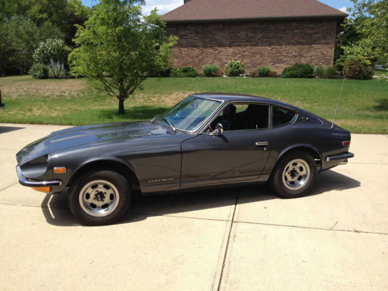
My '71 240Z