inline6
-
Posts
477 -
Joined
-
Last visited
-
Days Won
7
Content Type
Profiles
Forums
Blogs
Events
Gallery
Downloads
Store
Everything posted by inline6
-
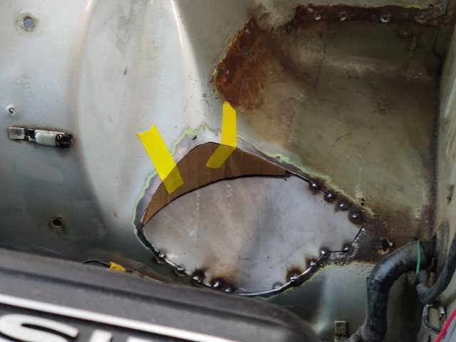
My efforts to get this other Z back running have expanded quite a bit beyond the rebuild of the 3.0 stroker motor. At the moment, I am working on repairing some rust in the floor panels. I have been watching a number of "Make It Kustom" videos on Youtube by Carl Fisher. In one of them, he creates some forms out of 3/8" plate to create a "hammer formed" part. Additionally, he uses a hydraulic press to "stamp" a recess into the battery tray he is making in the video. The rust in my floors on this car is not extensive. It is generally in the area of the large oval depression in the floor panel (on both sides of the car). Yesterday, I spent a few hours cutting out and grinding/filing on part of the form I plan to use to replicate the depression. On the right side floor, I only need a small portion of it. On the left side, I will attempt to make a full piece to replace the depression. I've never done anything with forms likes this, so we'll see how it goes. I will be using my 12 ton press because it is what I have to attempt to make the replacement part. But, I have been watching facebook for a suitable upgrade, perhaps a 30 to 45 ton press.
-
 Let me know if you have one, how much and your location - please. Thank you! Garrett
 -
I removed the rest of the list of items so I could mount the car on the rotisserie. With the glass still in the car, the center of gravity is quite a bit higher than the other Z I restored. When I went to rotate the car body, it got away from me and flipped upside down even with me trying to hold it. Luckily there was no harm done, and after adjusting the height a bit, the rotation of the car is easy to control now. As you can see, the floors are bare metal. They have been like this for about 15 years, but the car mostly has just been stored inside, not driven. It has been a major item on my to do list for this car to address a few rust though areas on the floors and to repair the dented up frame rails and floor. I will also be installing some plates for the safety harness belts. It will be very nice to get the floor fixed up and get the floor protected from the elements again, finally. The original frame rails are pretty bashed in. And the right side one is missing several inches of length at the rear because it rusted and I cut it off years ago and did a partial repair on the floor panel at that same location. I am using both a spot weld cutter tool and a die grinder to cut through the spot welds. The die grinder bit I am using works quite well. Same for the spot weld cutter. I worked on removal of the right "back half" of the frame rail yesterday for about 2 hours. I am only about 20 minutes from finishing the removal of it. Then I will remove the driver side one.

-
I started stripping the car today so I can put it on my rotisserie for few unibody sheet metal repairs... mostly the floor and the rear portion of the frame rails. I removed the heater core box, the engine and transmission, the front struts and the rear axles. I still need to remove the rear differential and the gas tank. I have a 2006 Chevrolet Corvette Z06, and one day I was looking at the brake vents and thought they would be good for the 240Z. And so they are! I installed these before I went to Road Atlanta in 2016 (I think)... this car has been off of the road for so dang long now! Anyway, they worked very nicely to cool my brakes. I made a custom fiberglass piece to adapt from the Xenon front spoiler to the round inlet of the Z06 vent, and used one screw and washer to secure the back of the vent to the inner wheel house sheet metal. The front brake rotors are Z31 vented units. I still have the unmodified backing plates on them, which is a mistake. It prevents air from getting to the back side of the rotors. Something else to address added to my list! Rear rotors are Z31 units. Calipers are 240SX. Axles are Z31 (with custom shafts). I bought parts from Ross back in the day (Modern Motorsports) for the brake and axle conversions. I bought the R200 differential from an eBay seller probably about 20 years ago. It was a NOS 200SX unit with a 4.11 ring and pinion. I removed the factory carrier and replaced it with a Nismo clutch type limited slip. I bought a high capacity finned differential rear cover and a billet transverse link from Protunerz.com during the recent Black Friday sale. So, I will be installing those when I put the differential back in the car. For now though, everything has to come off the car so I can make it light enough to put on the rotisserie for the floor repairs.
-
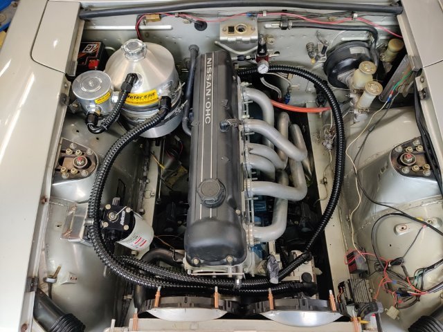
Here is the plate I made to assist with routing the dry sump hoses across the front of the engine: Here is the -16 AN hose that runs from the outlet of the tank to the inlet of the pump. It has a heat shield sleeve over it to protect it from getting overly hot from its proximity to the header. I put the intake manifold and carbs in place so I can determine how to route the coolant hoses from above the #4 and #6 exhaust ports to the thermostat housing.
-
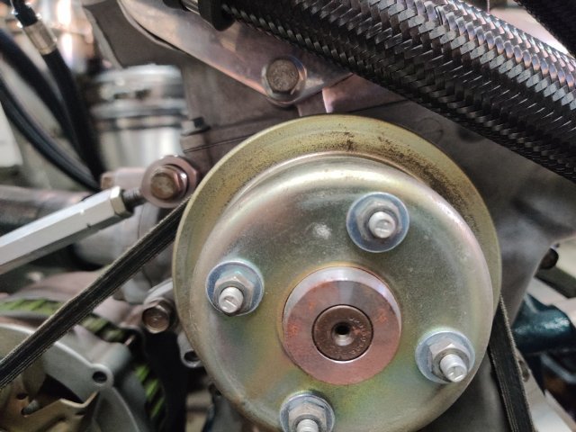
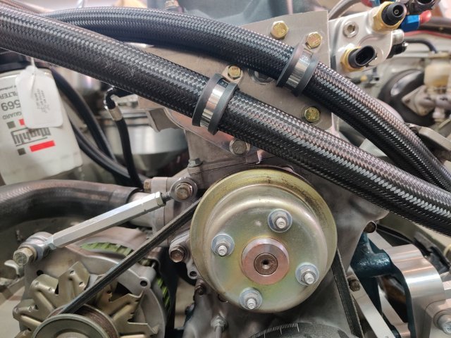
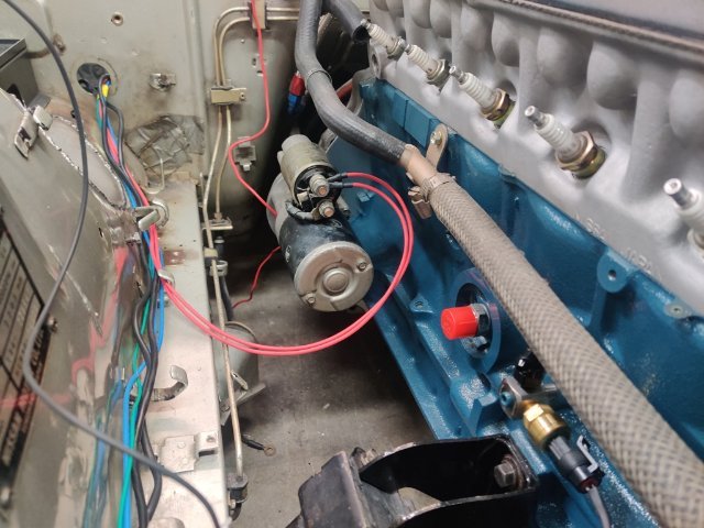
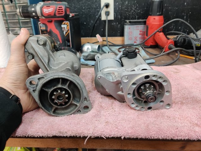
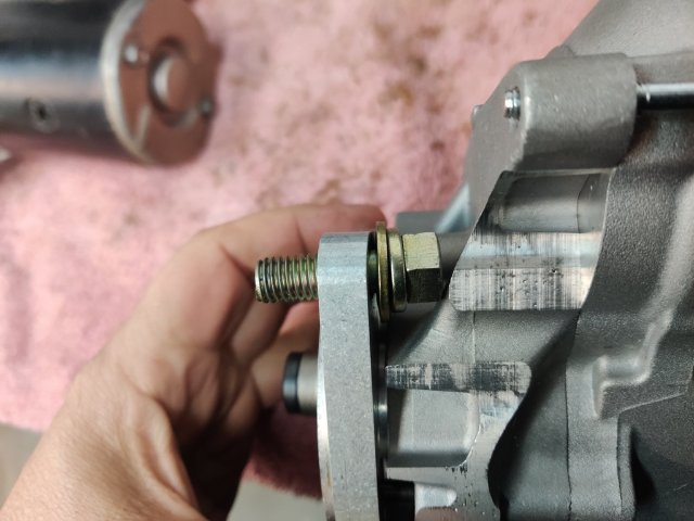
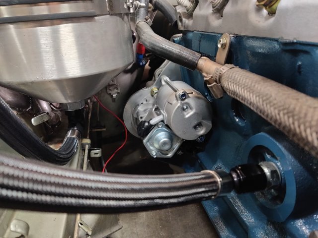
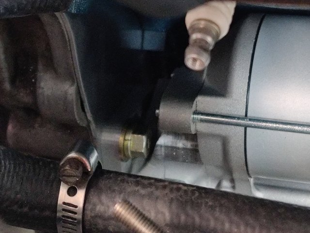
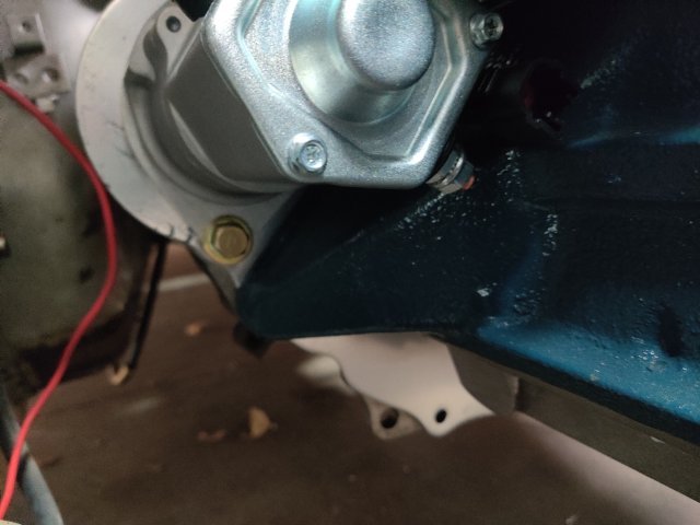
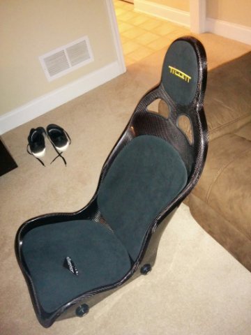
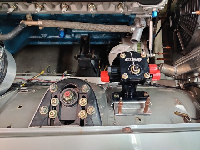
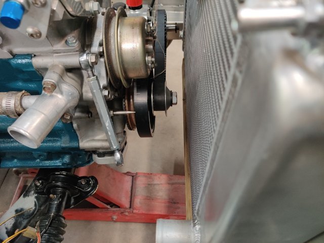
While working on modifying the engine compartment wiring harness, I bolted up the factory Nissan gear reduction starter that I have been using. While it cleared the dry sump oil tank, I was not happy with the location of the solenoid. It was quite close to the oil tank. I didn't recall it being that far away from the block. I looked for other versions of the gear reduction online, specifically hoping to find one with the solenoid located closer to the block. However, I was not able to find a factory one that was different. I was able to find this one however: https://www.classiccarperformance.com/products/datsun-240z-260z-280z-high-torque-starter?srsltid=AfmBOopbvBP16wSs5tvniJbqMb9CK2Kds63KS8RAjuCAWd7ZupU4Lbwm Because it features the ability to change the "clocking", I went ahead with buying one. After receiving it, I compared it to the one I already had: As you can see, the solenoid is in a very different location. In fact, out of the box, the solenoid bumped up against the block and the starter would not bolt up as it was delivered. I moved the mounting plate one hole location counter clockwise (referencing the picture above). In this position, the solenoid no longer interfered with the block. However, one of the mounting bolts had to be placed into position before re-attaching the mounting plate, as there was not clearance to put the bolt in after clocking to this position. That made installing the starter to the transmission MUCH more difficult. It was possible, however. Another issue that isn't great is that the positive terminal, where you bolt the positive battery cable, as well as some of the other items that have to be powered by this terminal (radiator fans), is on the underside of the solenoid, quite close to the engine block. It is just another inconvenience. So, I was able to achieve the overall objective - improving the clearance between the starter and the oil tank, but it was with some sacrifice of convenience in mounting and bolting up main power cables. In other news, I received the real oil lines that I had made. These are XRP Pro Plus hoses. I spent a lot of time and effort figuring out the routing, making "mock up" lines from pool hose, and waiting for them to be crimped and sent back to me. Yesterday and today, I worked on routing the two that cross just at the front of the engine. I have fabricated a plate out of 6061 T6 that mounts with some spacers at the front of the cylinder head. I have drilled holes and bolted rubber insulated P clamps to locate the lines precisely so that they do not rub against each other or anything else. The tank return line runs quite close to the water pump pulley. But, it is well located to eliminate interference. I also have little clearance between the studs in the water pump (holding the fan pulley one) and the Spal electric fans. Today, I removed the studs, and switched to the use of bolts instead to gain a bit more clearance there. It was super cold here on Saturday, and I wasn't feeling 100%, so not much time in the garage this weekend. In coming weeks, I plan to do some floor pan repairs. I will likely be pulling out the engine and transmission and differential... and mounting the car body on a rotisserie to facilitate that effort. I have a couple of patch panels (due to prior rust) that I'd like to redo, and I need to install mounts or anti-submarine straps (for the 6 point safety harnesses). Plus, I need to finish welding in the custom brackets I made to mount the Tillet carbon fiber seats.
-
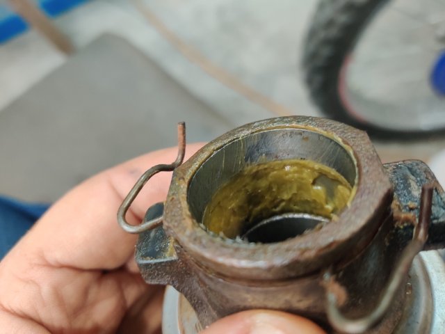
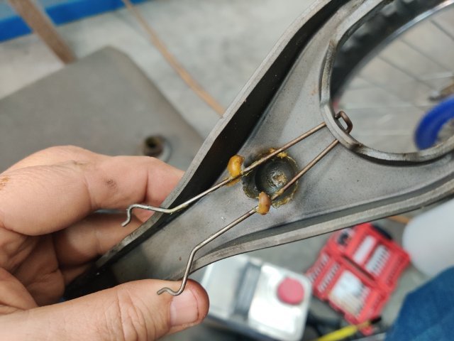
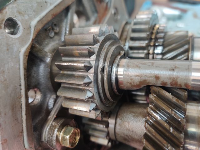
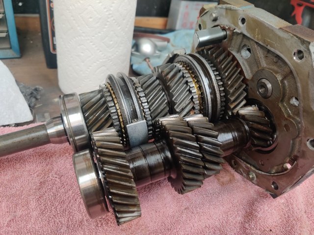
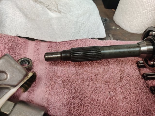
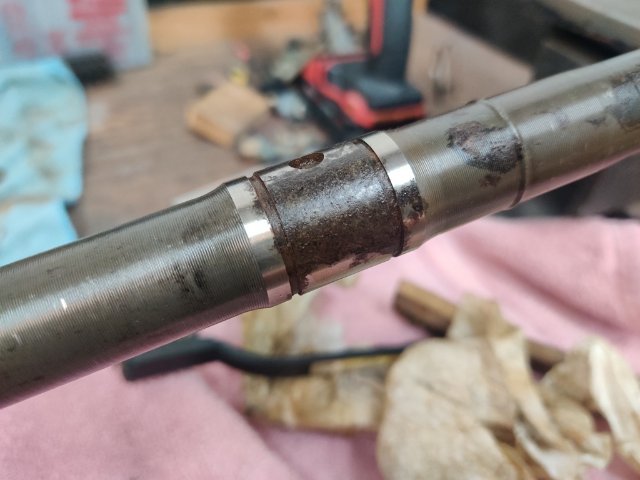
I think I scored with the purchase of a 240sx transmission. When talking to the salvage yard, they said the transmission came from a crash test car and it had 28 miles on it. Well... I was quite dubious, but they only wanted $100 more for it than one with 77,000 miles. So, I bought it. Today, I took the gear assembly out of the front and rear housings. The clutch release bearing sleeve has no visible wear marks and is packed with clean grease. The same grease is present at the clutch fork pivot. And, the reverse idler gear in this transmission which I have typically seen is chewed up on one side in used transmissions, looks like new (see the third pic)! Unfortunately, it has some specs of rust in a few places. There is one badly rusted spot on the main shaft under the speedometer drive gear (third pic) on about 1/2 of the surface on the diameter there. But, having looked it over pretty good, I think this will be a great transmission for the car. I don't need to use the speedometer drive gear because the car will now be equipped with a GPS triggered Speed Hut speedometer. I think I will just need to replace the rear most bearing (due to some light corrosion there), and give the gear set a thorough cleaning, and it will be good to go!
-
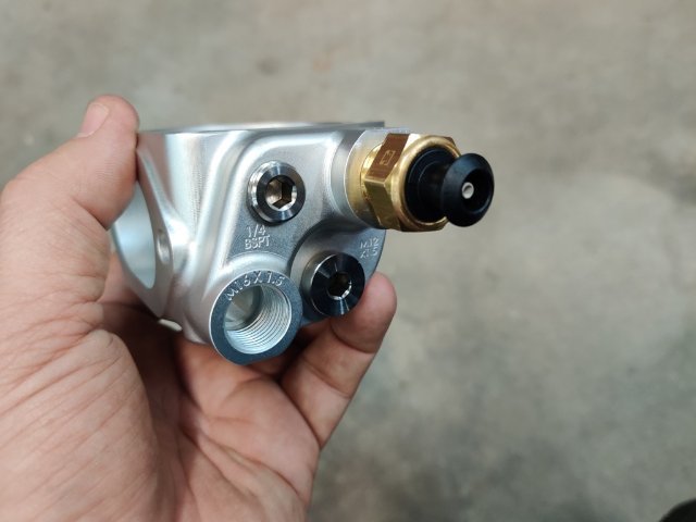
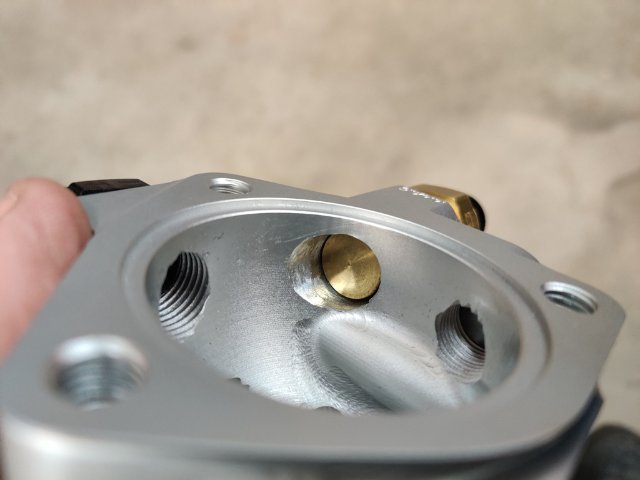
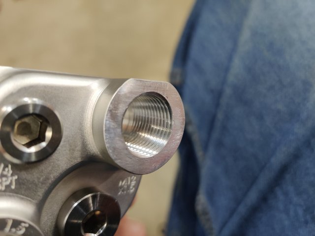
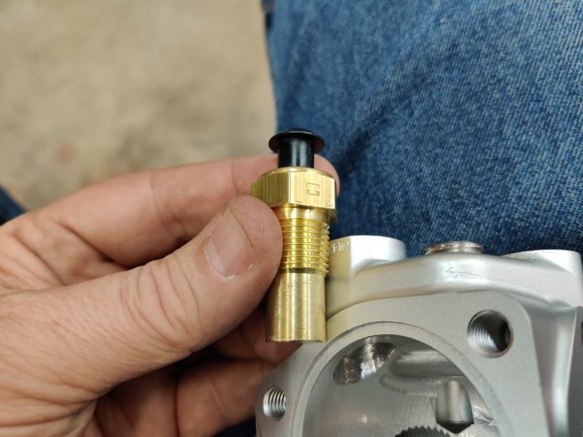
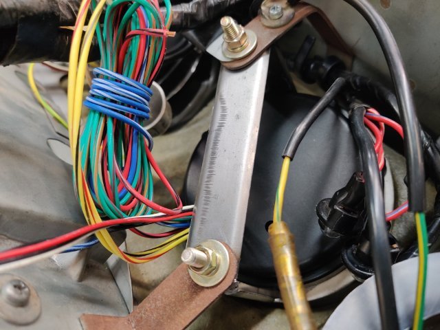
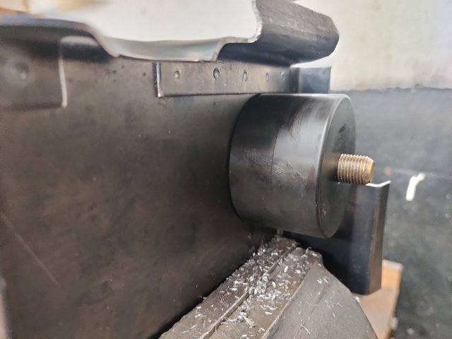
I found some time to work on the car today. Where I left off, I tried to fit the arms of the parts I bought, but I found that the parts did not fit well as is. They were a bit too long and the angle on them was not quite right. But, I was able to modify one of the 3d printed arms by cutting off the tab, and then drill a hole in the horizontal portion of the arm so that I could bolt it to the original "L" brackets that were utilized with the stock gauges. Then, I modified the rest of the brackets to fit the trio of gauges in the center of the dash. Though upside down, they look nice. However, the OD on the bezel portion of that locates the gauge in the dash is also not quite right. I have been in touch with the seller (maker of the 3d printed brackets) on eBay. He is going to make some new front portions that have a wider OD and send them to me. I will still use the modified arms I already have. Changing projects (3rd pic): I had need of mounting a 3/8 NPT threaded radiator fan switch. I came across https://protunerz.com/ while I was shopping on Black Friday - I had never heard of them before. They make some nice billet parts for Z cars. I decided to buy this thermostat housing because it has several existing openings for fittings. In addition to the radiator fan switch, I needed a spot for the water temp gauge sender, and two openings for custom lines that I have on my head to flow coolant from above the #4 and #6 cylinders. To fit the 3/8 NPT rad fan switch, I had to drill out the M14 opening. That was not fun using a vise and drilling freehand with a 37/64" drill bit... and running the tap by hand. I wish I had a drill press, though I still think it could have been a disaster trying to run the drill bit through the existing threaded hole. Doing it by hand, the bit "caught" a couple of times nearly wrenched my arms around. I had to finish the opening with a round file and VERY carefully tap the hole with a 3/8" NPT tap. It did come out well though. Only thing I wonder about is whether the sensor might not work properly without more of an "air gap" between the housing and the body of the sensor. I am assuming that the gap around the body of the sensor just needs to be large enough for coolant to get in and surround it. But I wonder... do I need to grind the opening up a little bit more around the sensor (3rd pic above) for proper function?
-
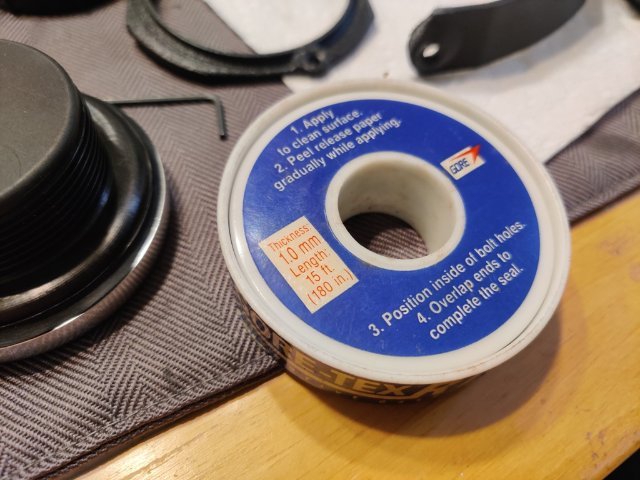
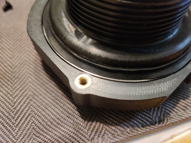
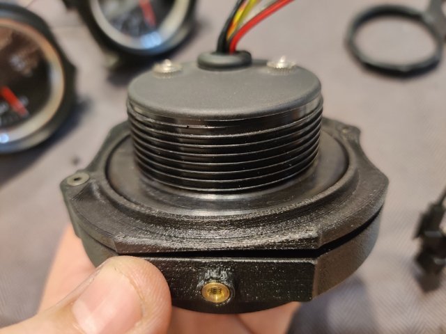
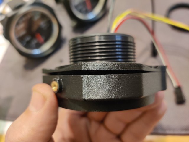
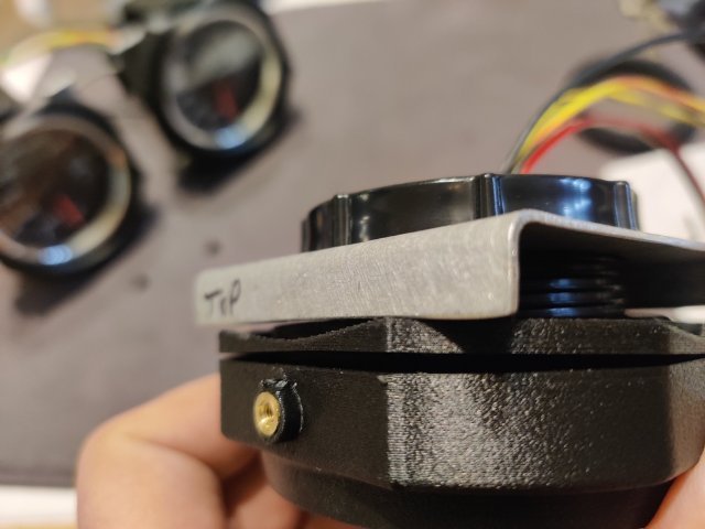
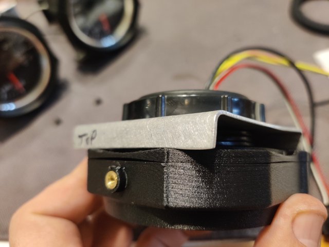
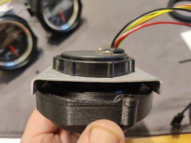
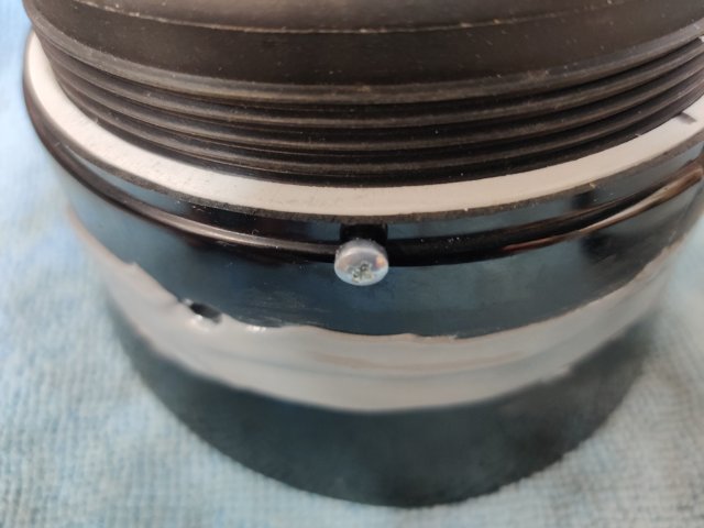
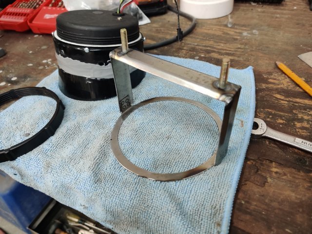
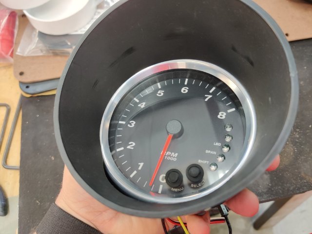
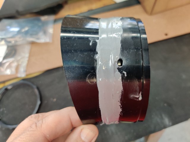
I purchased some gauge mounts from a seller on eBay for mounting the new Speed Hut gauges in the middle of the dash. They are 3D printed items. The design is pretty good. The plastic seems sturdy. And they incorporate metal thread inserts. The screws have a taper head, so they self center, and fit of the various parts is very good. However, I found that the gauges were loose when fitted to the housings with the backplates (which hold them in the housings) bolted tightly in place. The gauges rotated easily in the housing as there was no clamp force against the back of the gauge to hold the gauge forward against the "stop" portion that the bezel of the gauge is supposed to fit up against. After thinking about solutions for a bit, I pulled out some ancient Gore-tex I have. Basically, it is rubber gasket material with an adhesive on one side. It comes in handy for a lot of things. In this case, I cut a strip and ran it around the back of the bezel on the gauge. I fit the gauge into the housing and then pressed the backplate against the new Gore-tex rubber gasket to seat it into place. I then briefly removed the gauge from the housing and took this second picture (below) which shows how the new gasket deformed under "crush". Third pic shows that as well as the metal insert in the gauge housing. Another issue to overcome though was that the backplate only has two screws to clamp it to the housing, 180 degrees from each other. After I put the gasket in place and assembled the gauge in the housing, the backplate only pulled tight against the housing where the screws bolt up to the housing. See the first and second pics just below. I realized that I could take the aluminum mounting brackets I had already made during an initial attempt to mount the gauges in the dash, and flip them (back to front) and use the Speed Hut gauge mounting rings to resolve the situation however. See the third pic (above). While I thought I wouldn't need them any longer, these aluminum brackets ended up coming in handy. I simply screwed the Speed Hut mounting rings tight against the aluminum brackets... and this pushed the edges of the aluminum brackets against the plastic backing plate at the points which were not seating against the back of the housing properly. So, with this distribution of force at the non-secured parts of the backing plate, I was able to resolve the issue. I see now that I didn't take a picture of the other part of the gauge mounts. There is an arm that attached at the top and the bottom of the housing in the same way that was done on the stock 240z gauges. I hope I won't have any issues with that part bolting up, or with the gauge housings fitting in the dash holes. I will probably check that out this weekend.
-
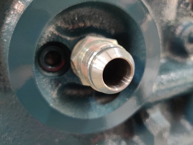
The head is an E88 casting which came from a 240z. So, that opening was there for the stock fuel pump already. Though not a desirable head as is, this one has been milled quite a bit to get the combustion chambers to be usable for this engine set up.
-
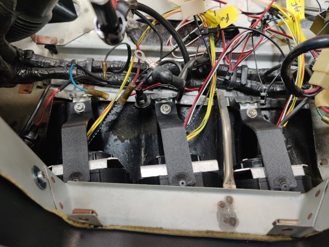
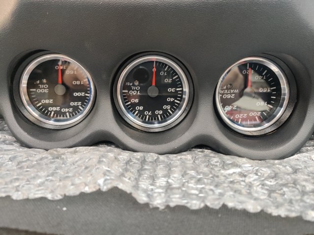
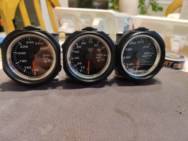
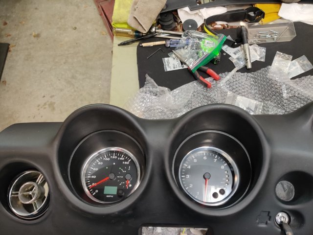
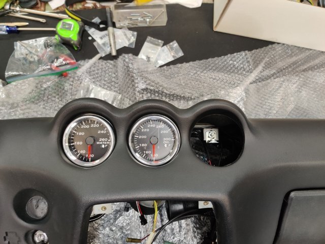
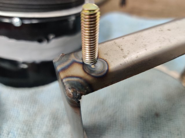
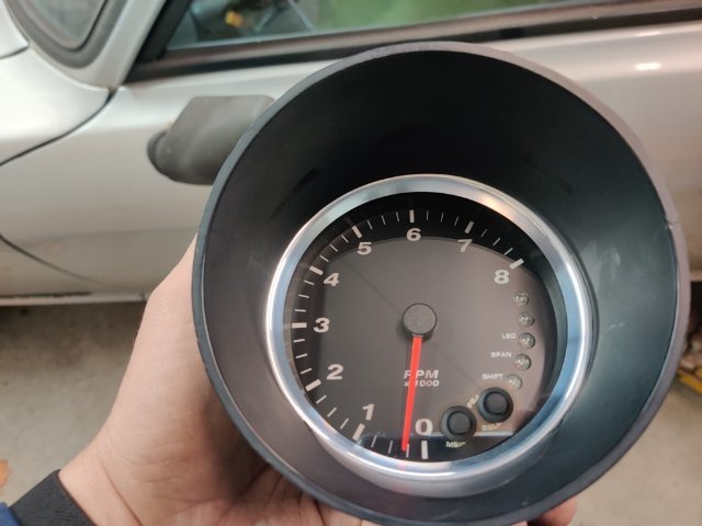
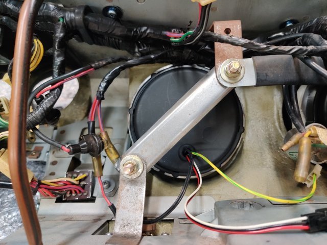
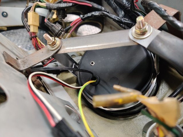
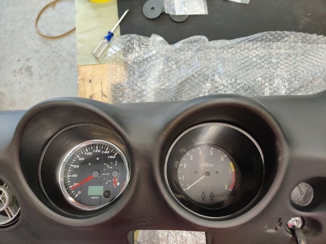
I worked on mounting the gauges a bit more this weekend. Some pics showing what I ended up doing for the tachometer: Basically, I drilled 4 holes through the outside of the modified gauge pod and into a sliver of a pvc pipe end cap. I just cut a section off the cap to make a round ring about 1/4" in thickness. The gauge goes in and seats against the much hacked remainder of the original gauge pod. Then the pvc ring goes in. Then the screws go through the housing into the pvc ring. This locks the gauge in place in the pod. Then the metal frame I made slides on. Then the trim ring that comes with the Speed Hut gauges gets spun on to lock the metal frame in place. I welded some M6 x 1.0 studs onto the metal frames. Backside showing metal frames for the tach and speedometer being secured to the original gauge mounting brackets. I also checked the fitment of the pod gauges. Because the bezels are a little under the size of the dash openings, I decided to buy some 3D printed mounting brackets I found on eBay. They will add a small ring of black trim around the gauge and facilitate a snug fit in the cut outs. They should be here in about a week. For the three center gauges, I chose water temp, oil pressure, and oil temperature, which I will probably install in that order from left to right. I have started looking at the wiring instructions... and comprehending what has to be done to get these functional. That is where I will pick up when I can.
-
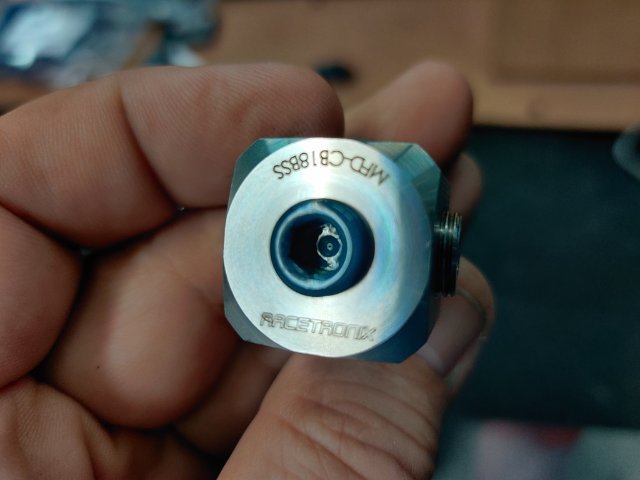
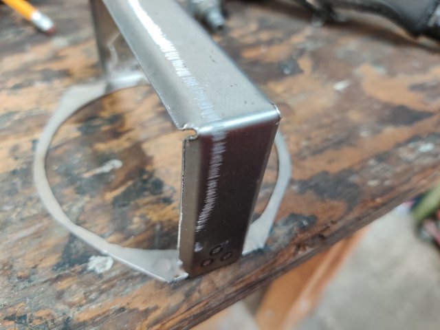
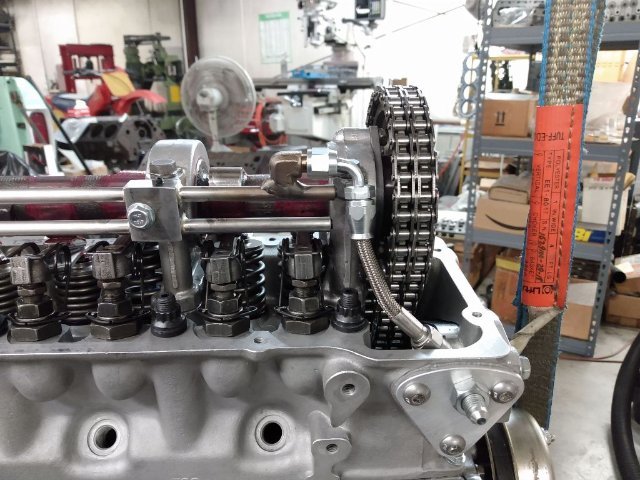
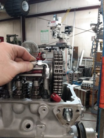
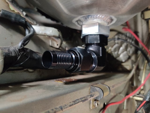
I switched gears a bit this weekend. I have started working on mounting the SpeedHut gauges I bought several years ago (during a Black Friday sale). At the block, I installed this distribution block. Pretty cool that it has 1/8 BSPT male threads to go into the block, and 4, 1/8 NPT outlets (and one 1/8 BSPT outlet). The black, 90 swivel in the picture is going to supply oil directly to the cam spray bar. Pictures from my engine builder when he was making the spray bar and fitting it to the engine: Getting the speedometer and tach mounted... has been very involved. I wish I could say it wasn't a difficult job, but the problem with adaptors that are available is they compromise the look of the finished installation. I like the look of the polished aluminum bezels that I chose. And to get them to show somewhat properly, I had to modify the stock pods a ton. For the first one, I bought some PVC items from Home Depot. I had to whittle them down to nearly nothing and glue them to what remained of the pod plastic housing. It's not worth describing how I did it as there has to be a better way. For the second one, I was able to repurpose some of what I cut off from the first pod... but still not easy, and not worth sharing what I did specifically, as no one would want to spend the amount of time and effort I did here. Anyway, I hope to finish mounting the gauges in the dash (removed from the car yesterday) today. Because the new gauges are much shallower, I needed to make a sheet metal bracket to support them from behind. The only way I could think of to do that was to make a large ring to go around the OD of the gauge (the speed hut gauges mount using a large trim ring). To the flimsy ring I made, I spot welded another bracket I made. I was able to bend each of the edges of this part about 45 degrees using my metal brake which added some rigidity. The final thing I need to do is drill holes and mount some threaded studs. When done, I will be able to secure the gauges to the dash using the stock mounting locations and hardware. The new gauges will not sit as far back in the dash. Again, due to their OD and fitting to the stock pod, I moved them forward a bit to get the bezel visible - this depth is where they look best.
-
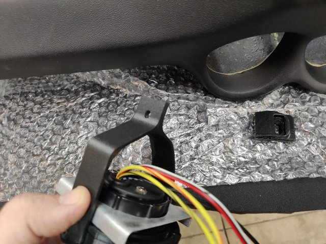
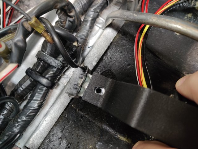
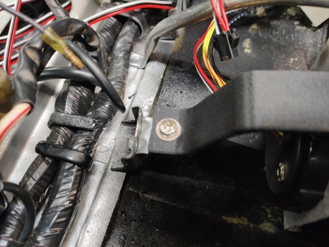
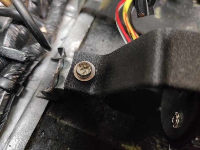
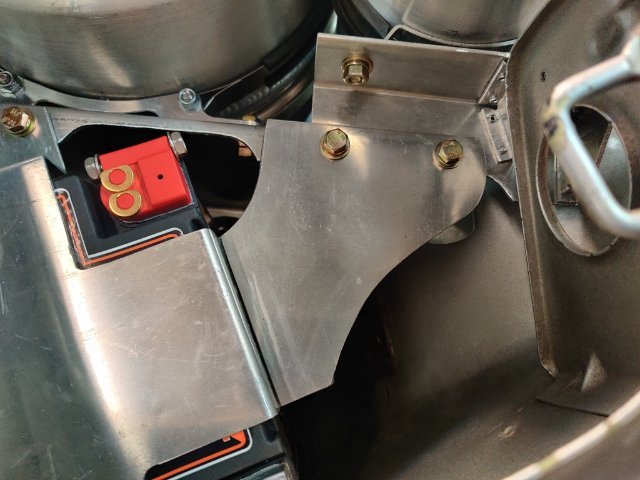
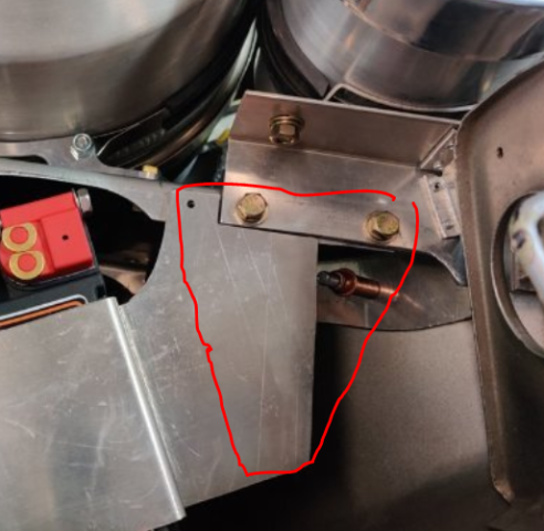
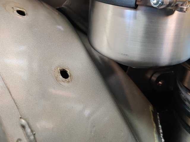
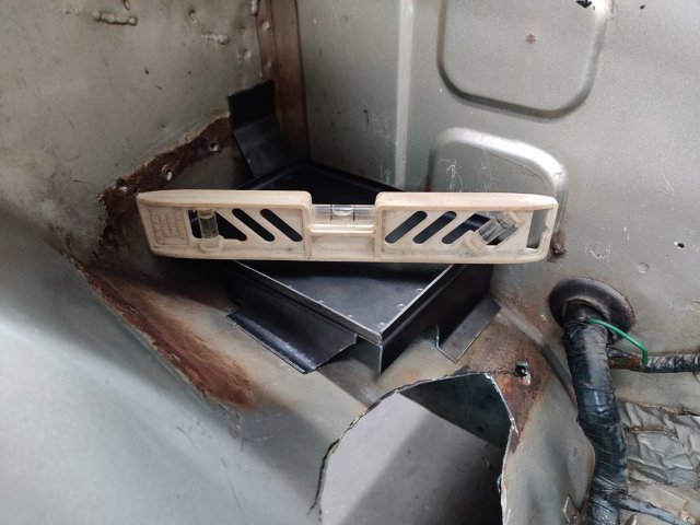
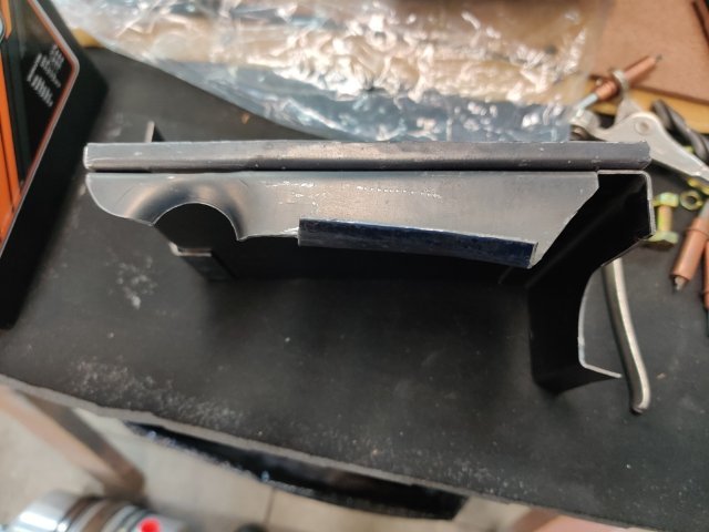
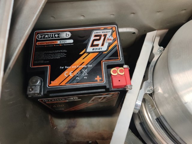
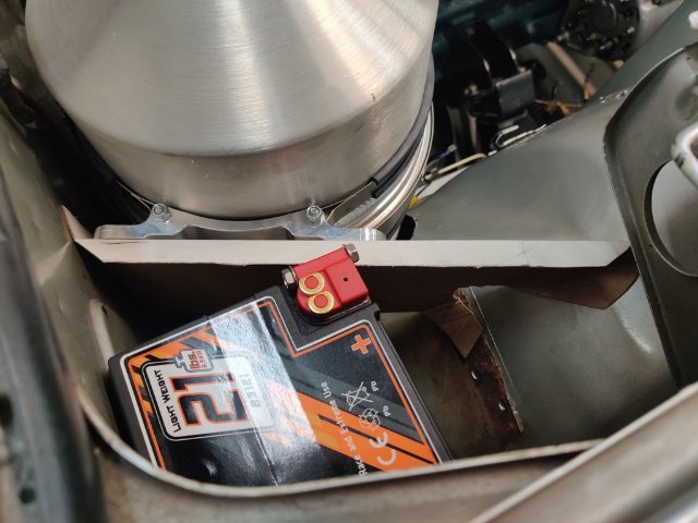
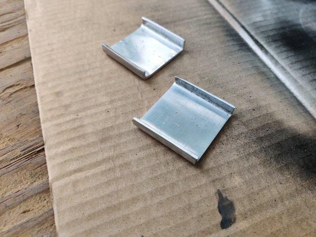
@tube80z - so I have done what you suggested here: I put lips on the battery tray to keep the battery from shifting at the bottom: The battery hold down "plate" has a couple of jog bends to capture the angled bracket that the tank mounts to. I just need to secure this plate I made (what I was referring to with the red outline above) to the main plate to finish this up.
-
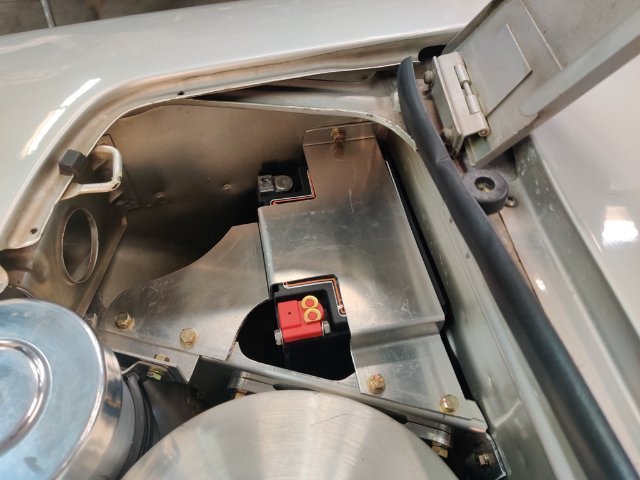
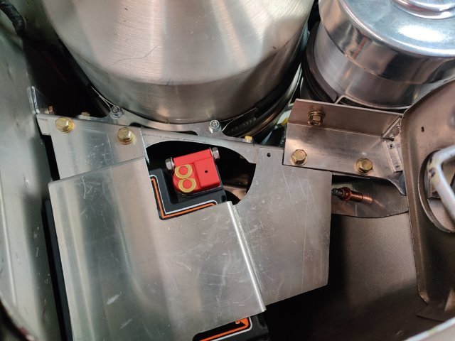
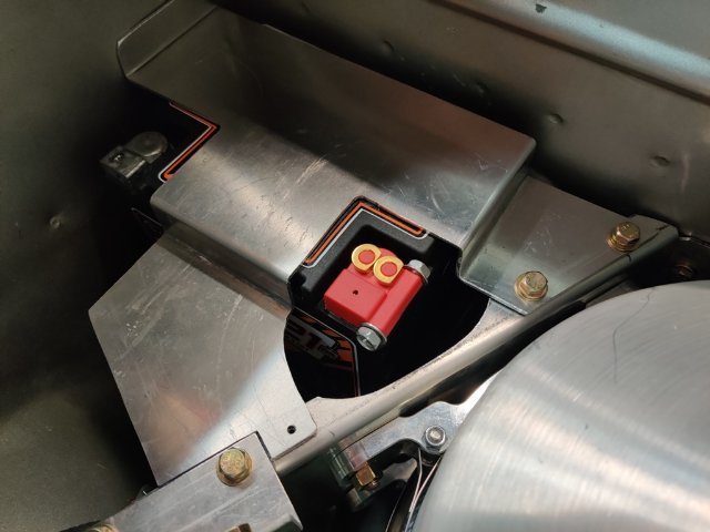
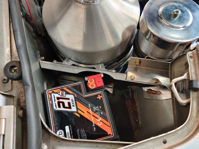
It seems there isn't much activity on this forum vs. about 10 years ago. I guess not as many of these cars are still being modified now. Anyway, an update on some progress. The pool hose I am using here is just for mock up purposes. It has the right ID to fit tightly on the fittings. I just heat up the the hose (a plastic/vinyl material of some sort) and then slide on the fitting. I believe this is helping to establish the actual hose lengths I need as well as "clocking" or indexing the fittings to the hose. Additionally, though I did not plan it this way originally, I came up with a great design for securing the battery to the tray... and made this upper battery mount bracket in such a way as to tie in to the bracket that I made to mount the oil tank in the car. The upper bracket I made today not only clamps the battery in place, but also ties into the oil tank bracket and the engine compartment panel, triangulating everything. This design makes the mounting for the tank very rigid. I still have a bit to figure out with regard to mounting the forward most part of the bracket that I made today to go on top of the battery. I think I may cut a plate like this red outline and rivet it to the upper battery bracket. This panel will sit atop of the angle piece that presently holds the breather tank in position. Then the two bolts (within the red outline representing the new panel) will join all three layers. The result here is that the triangulation appears to substantially strengthen the tank bracket. I won't have issues with the weight of the oil in the tank causing the brackets to bend/fatigue.
-
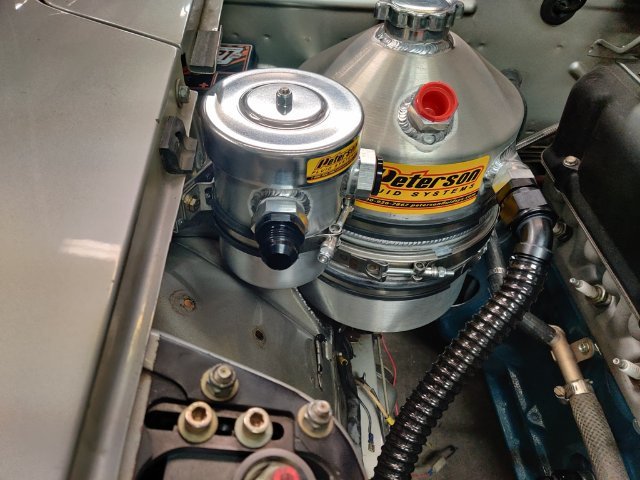
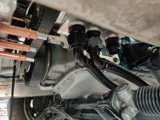
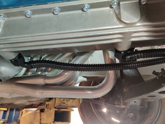
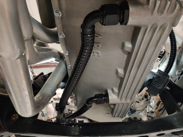
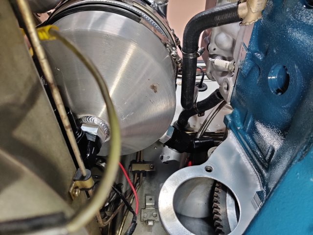
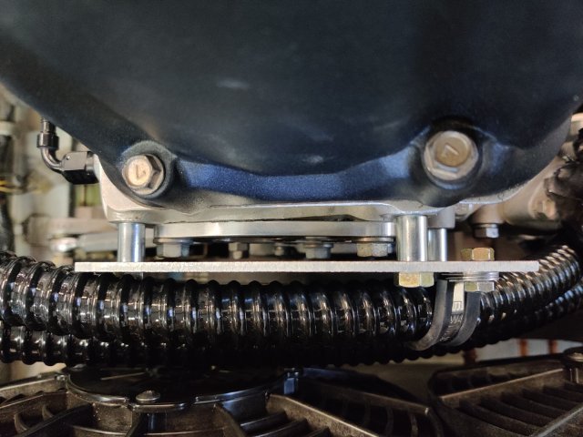
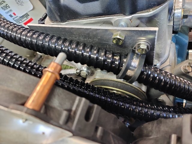
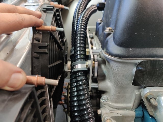
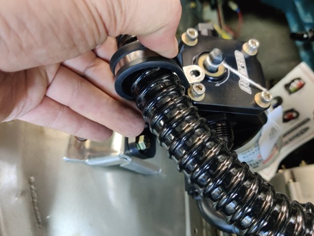
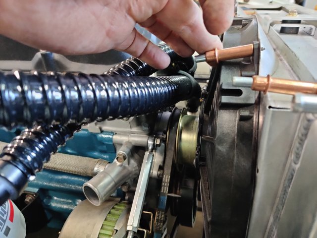
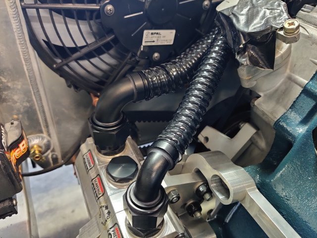
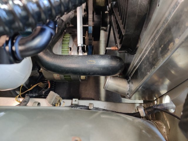
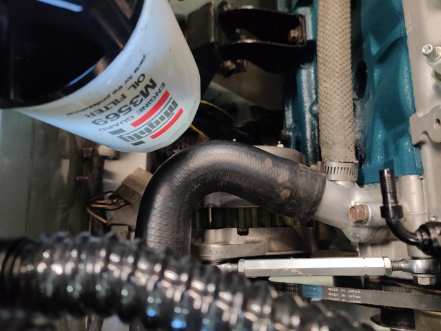
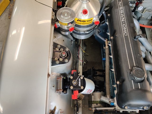
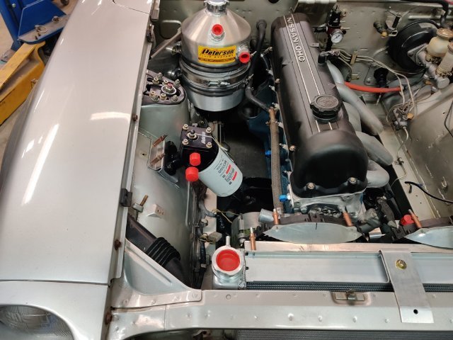
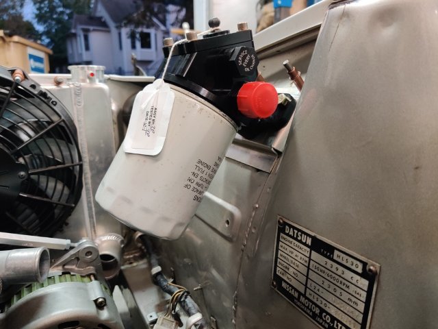
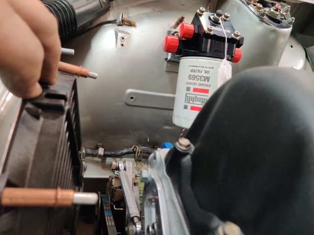
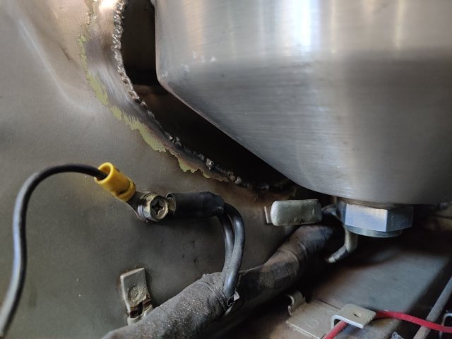
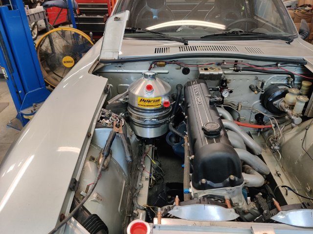
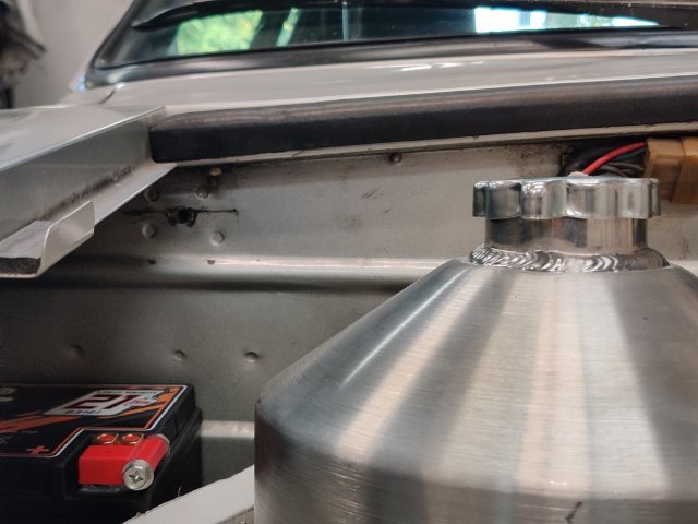
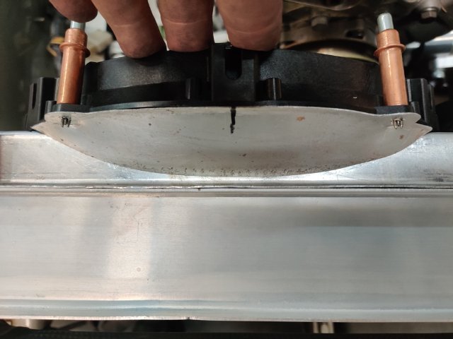
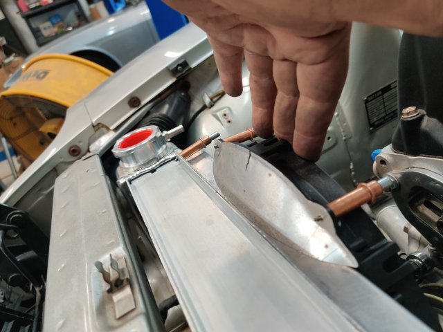
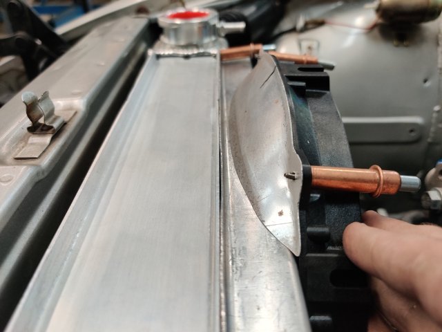
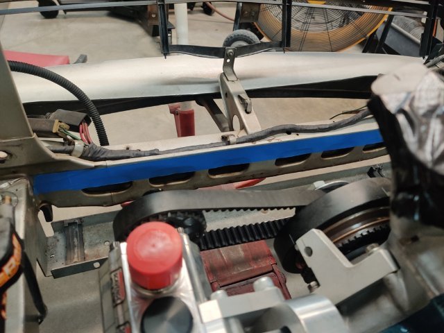
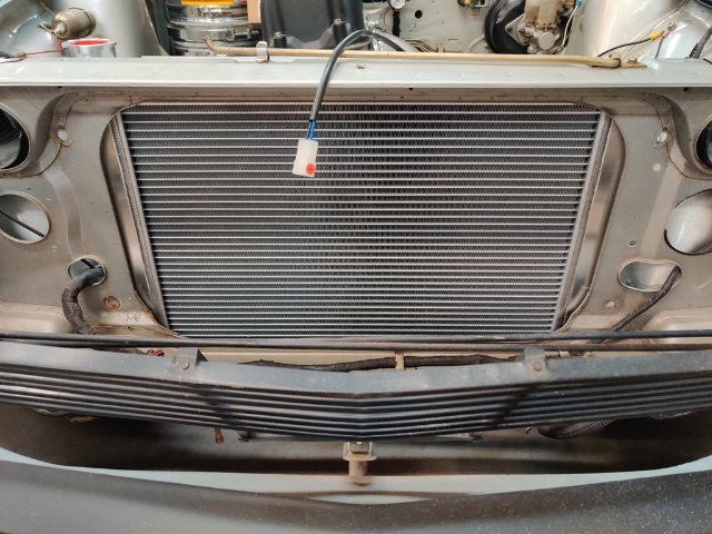
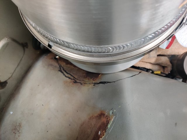
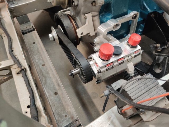
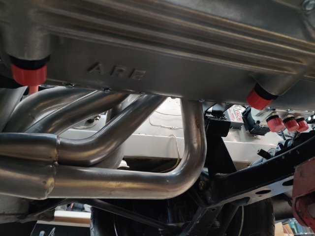
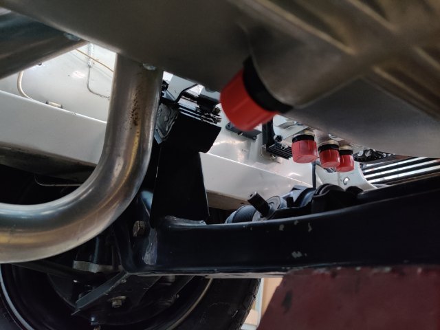
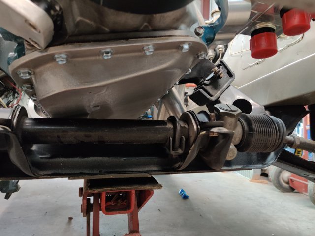
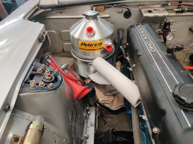
Final oil breather tank location and clocking. I will route a short hose from the tank vent out (red cap) to the black male AN fitting on the breather. The other fitting opening on the breather will be routed to the valve cover later. The hose in the picture is some kind of "pool" related hose. It is made out of plastic/vinyl with one coil wire in it. The ID is about the same as the AN fittings. I have one for -12 AN and one for -16 AN. I just heat the end up a bit with a heat gun and quickly push it into place on the fitting. It is working nicely to create "mock-up" lines. Two scavenge lines from the ARE pan to the pump: A special short 90 degree -12 AN was needed at the bottom of the tank. Tank clearance with all of it's surroundings is tight. Routing of two lines across the front of the engine... it took a while, but I finally thought up the idea to fabricate a plate for use as a securing point for P clamps to hold the lines securely. I used some dowels to space the plate away from the head and Kameari chain tensioner. I may shorten these a bit. The routing of the lines (one is -16 AN size and one is -12 AN) across the front of the engine - the lines are safely out of the way of the water pump pulley. I need to buy a longer bolt for the corner of the remote filter to secure another P clamp here (first pic). You may have noticed that I fabricated another remote filter mounting bracket. This one changes the angle of the oil filter so it is more vertical than the prior one. I did this when I realized that the -12 AN outlet doesn't need to pass close by the strut tower - instead, it goes directly to the original filter mounting location on the engine block. I previously was thinking it needed to go to the tank and was planning to secure the line with a P clamp to the tower. I put a stock lower radiator hose in place to check the situation out. Removal of the filter will not be difficult. As you can see in the last picture, I will have to modify the radiator coolant outlet somewhat. I won't be able to use the stock hose as is either. So, I need to figure out how to proceed to resolve this issue. I likely will remove the pipe outlet from the radiator, and modify it (or buy another) and weld it back to the radiator, changing the angle in the process. An "L" shaped tube with the same diameter as the stock hose would be a good solution here.
-
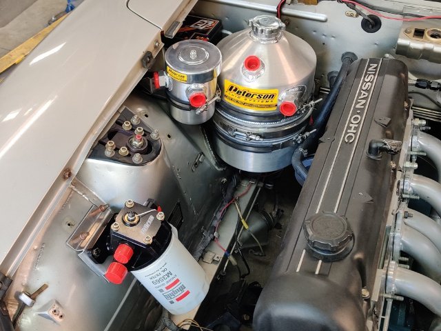
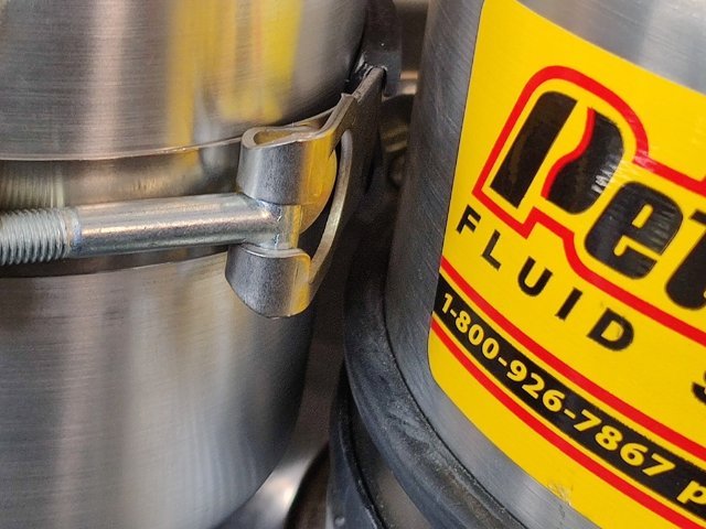
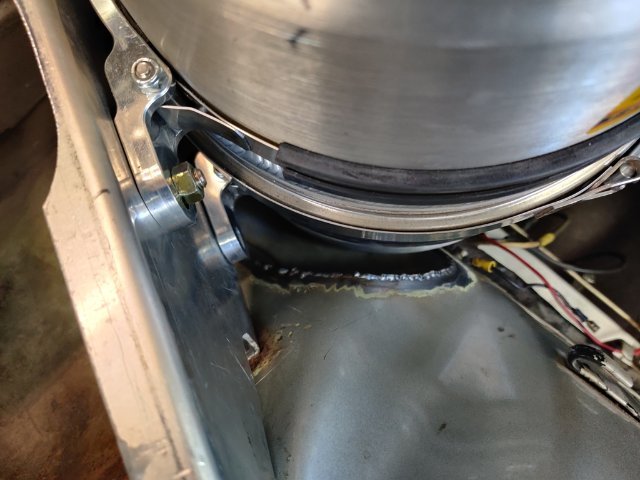
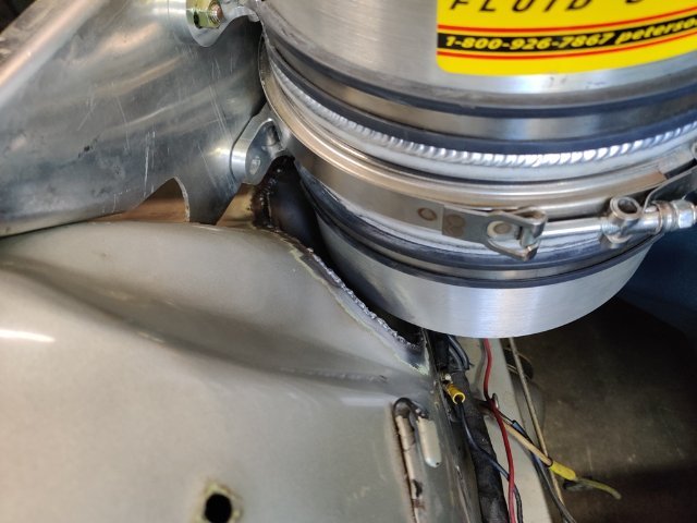
Next up, is mounting the the breather reservoir. Things are tight... very tight. But I think this location will work. I was able to use a simple "L" shaped bracket, bolted to the top flange of the bracket I used to mount the tank. It wasn't very rigid... until I tied it into the vertical steel panel that drops down from the inner fender support. Now, the main panel (and breather tank bracket) is secured on three of the four sides. I am pleased with the result. I just need to tweak the mounting tab locations every so slightly to get everything vertically set at the proper angle - it is a shade off at the moment. Though a pain, I can remove the battery without disturbing any of the oil system. This was one of my requirements when coming up with mounting the brackets. Now, it is time to finalize the order for the fittings.
-
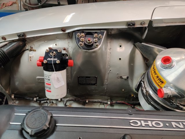
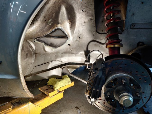
Next up is the oil filter remote mount. I fabricated an aluminum bracket to attach the mount to the right inner wheel house. On the 46 BRE Z, the mount is on the inside of the strut tower. I wanted it to be a bit more forward in the engine compartment, as I think that facilitates a slightly better routing of the line from the "out" of the remote mount to the input on the engine block. Essentially the line just needs to turn 90 degrees to go into the block, plus some angle to handle the height difference. Here are some pics from various angles. I am planning on running the supply and scavenge lines across the front of the engine at the front "cover plate" location, where I am running a Kaminari timing chain tensioner. I could fabricate a bracket to mount the oil filter more vertical than I have done here, but I chose this angle to keep the outlet tangential to the shock tower innermost surface. I plan to secure the hose with a rubber lined "P clamp" at the shock tower and then bend the hose for a straight (ish) run to the block. I also am thinking that angling the oil filter out like this will allow me to run the scavenge line between the wheel house and the filter (in the gap that exists) and secure the scavenge line also to the shock tower with a P clamp. If the oil filter was vertical instead, the scavenge line would have to pass by the filter on the other side, where it would be free floating - not as easily secured. That is my thinking anyway. I have never run lines like this for a dry sump system. So, doing what I think is best.
-
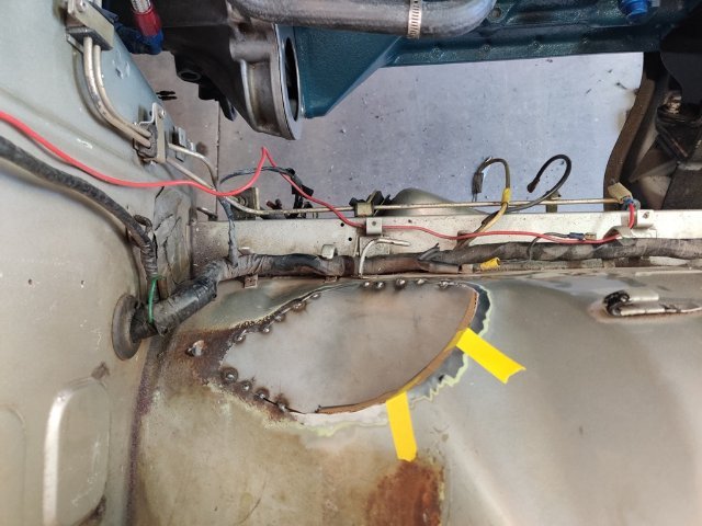
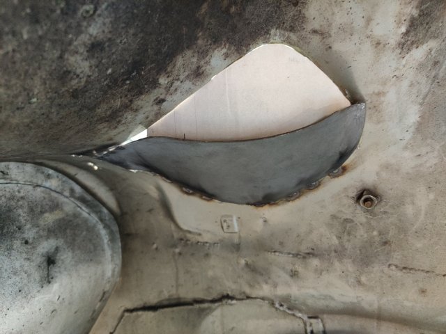
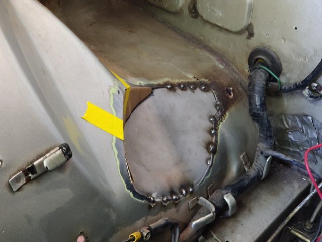
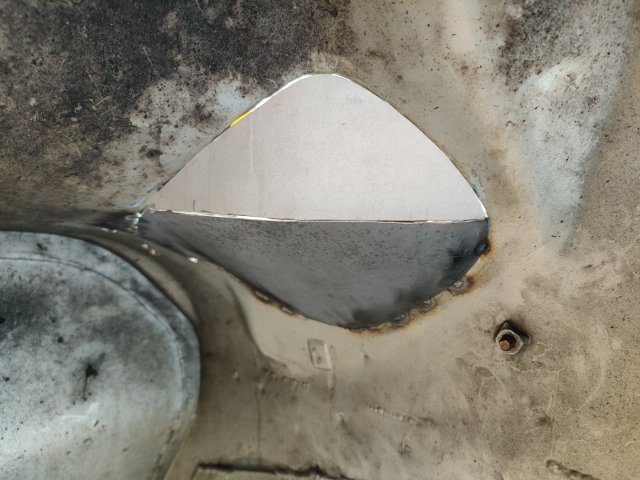
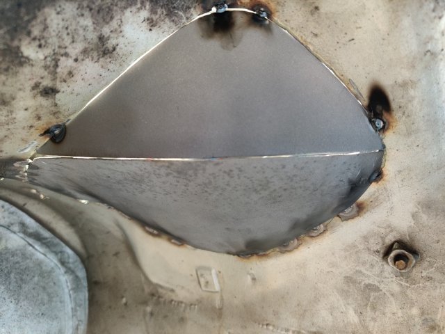
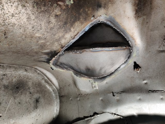
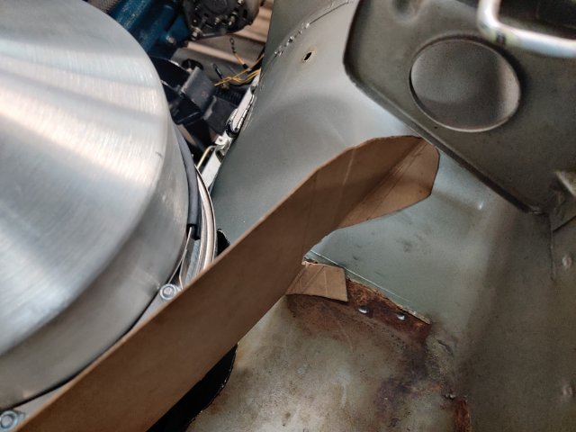
This past weekend I made some more progress. I worked on cutting the right inner wheel house, made two new panels, and welded them into place. I used thin cardboard to make templates for the two replacement panels. After tack welding the lower panel in place, I made the second, upper panel. I checked tire clearance, and then finished welding them in. I think my welding regulator is inaccurate. I was getting some contaminated welds until I bumped the gauge up to 27 psi (I have always used 20). Once I bumped the pressure up, the welds got a lot better. Metal fabrication like this always takes me a long time to do. I am glad this part of the work behind me now. I ordered a remote filter assembly and mount, and a breather tank this week end. They should be here in a few days. Then I should be able to finish up my order for XRP fittings for the entire oil system. I plan to buy the fittings and install them all so I can check/set orientation. Then I will buy some corrugated pool hose for the purposes of mocking up the lines. I will cut it to fit for each hose assembly, and then mark the hose and fittings to "clock" them in the correct orientation. Finally, I will box all of them up and ship them off to have an XRP distributor install Pro Plus Xtreme hoses with crimp on fittings.
-
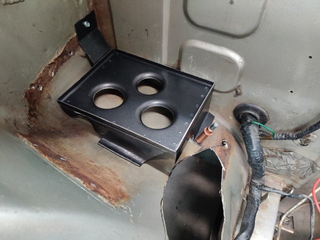
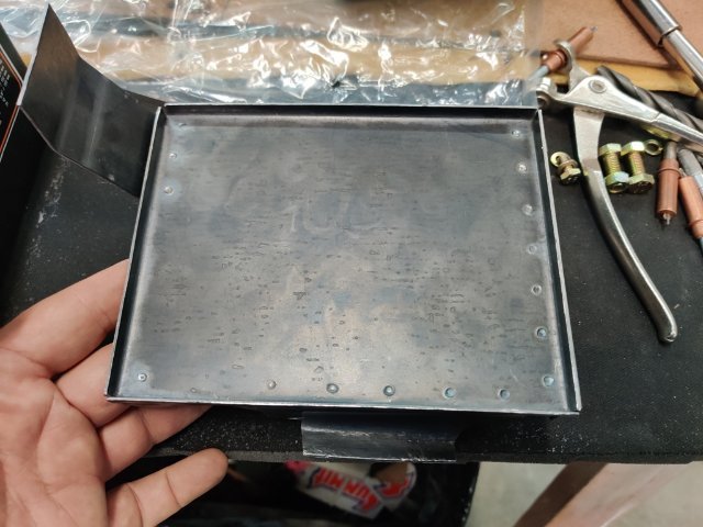
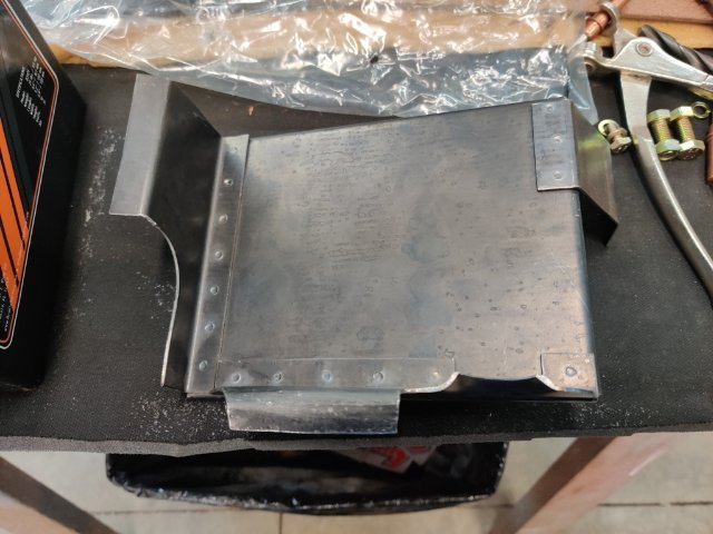
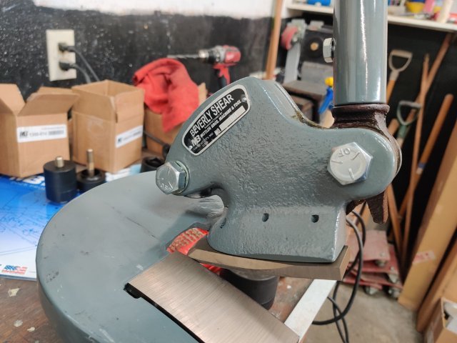
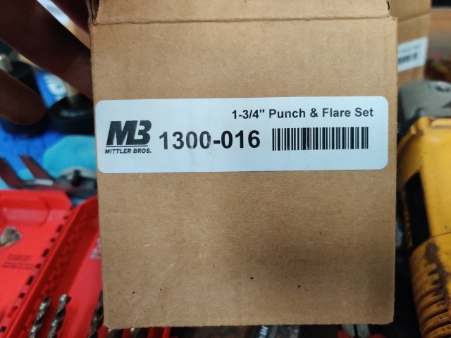
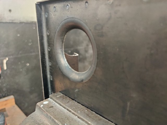
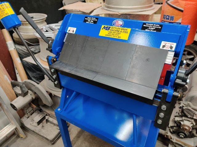
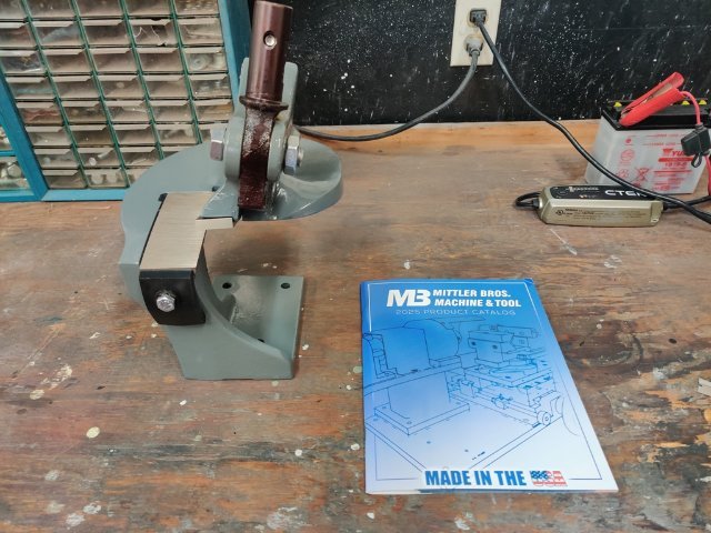
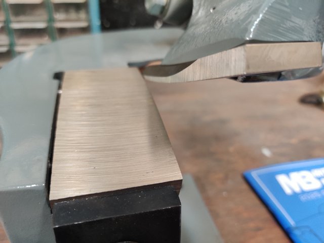
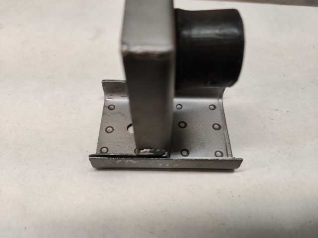
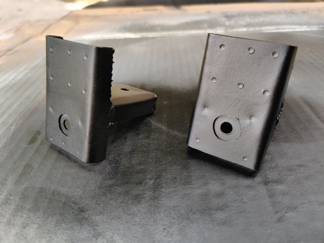
After several weeks of various distractions, I was able to commit a bunch of hours to working on the "track car" this weekend. I recently purchased some nice tools to make fabrication projects easier. Here are some pics of tools: And with those on hand, I was able to make a nice battery tray for the new Braille battery. The spot welder I bought several years ago was awesome to use as well. I am very happy with how this part came out, even if it did take me about 9 hours to make it! I still have to design a battery clamp down mechanism to hold the battery to this new tray, so I will work on that soon. With the battery tray temporarily in place, I again mounted the dry sump tank, and started figuring out all the fittings I will need for the lines for the dry sump system. I plan to order those soon and then mock up some hoses.
-
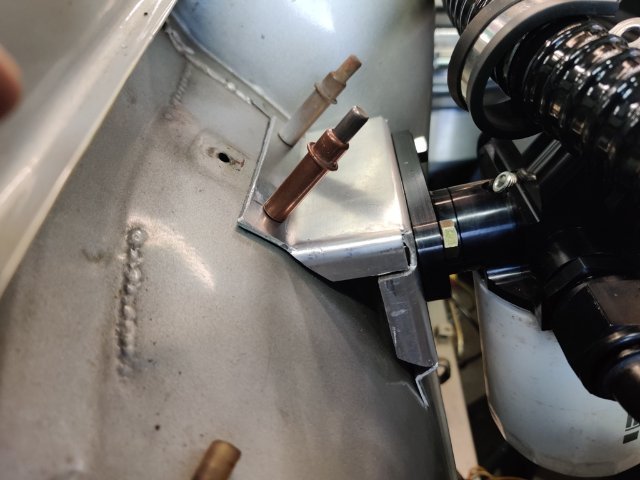
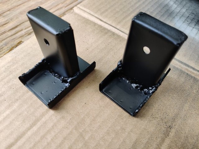
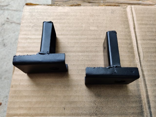
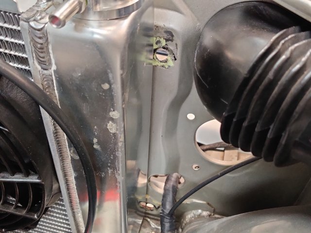
Today, I turned my attention to mounting the oil tank. Like the radiator, getting it to fit is quite a challenge. When placed against the firewall, the mounting brackets interfere with the brake and clutch hard lines, and the raised "ribs" in the firewall panel. I could space it out from the firewall, and still mount it there, but I came up with an alternative that I like. It will allow me to mount the tank far enough from the firewall to avoid wiring and hard lines and "ribs". I will be fabricating a mounting bracket which will connect diagonally from the firewall to the right inner fender. The final location of the tank will be just low enough to keep the filler cap from hitting the hood, and the drain will be located a couple of inches above the frame rail. Additionally, I purchased a Braille battery which is much smaller than the original. I will make and weld in a steel platform for it that will be similar to how it was done originally by Nissan. It will be a smaller platform, of course, but I will weld it to the inner fender in two locations and not to the firewall. At the top and bottom of the oil tank mounting bracket, I will put a 90 degree bend to add rigidity. I have some 1/8" thick 6061 aluminum I will use. Additionally, I have some aluminum angle. I may reinforce the top edge of the mounting plate with some of that. The bracket will be mounting to the firewall with two bolts (a reinforcement plate will be on the backside of the firewall), and to the front inner fender with two bolts. I may tie into the top edge of the oil mounting bracket in some way... to secure the battery in place. I want to be able to remove the battery without having to dismount the tank. So, that will be guiding my design effort for what I come up with to secure the battery in place.
-
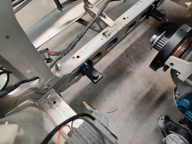
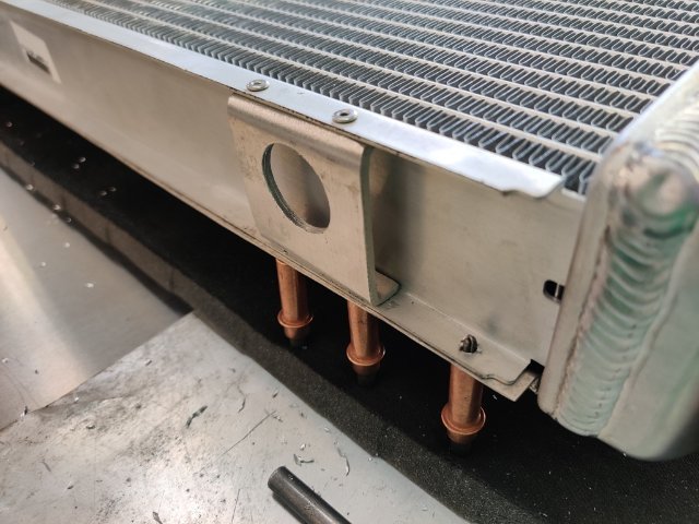
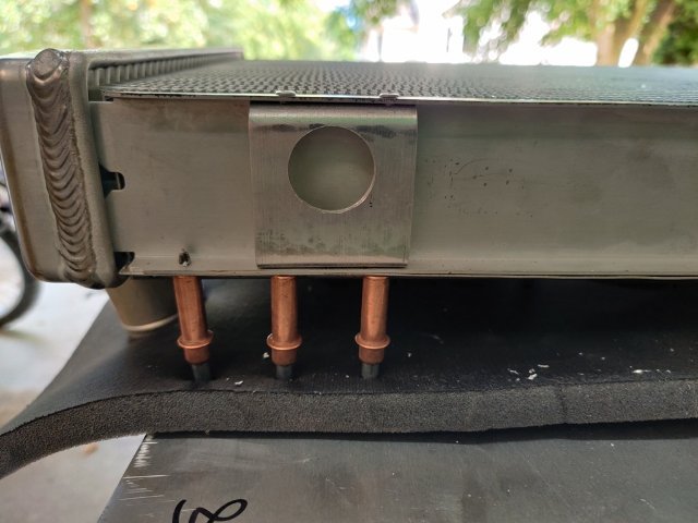
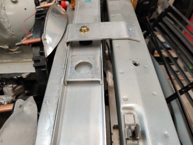
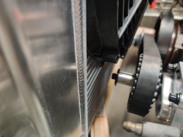
Another weekend of work has gone by, with my efforts spent on mounting the radiator. Time spent thinking of bracket design was more than I would have preferred. However, I did come up with something that will work well. Had I to do it again from scratch, I would use thicker sheet metal. What I have done here instead is fabricate up some brackets using some .032" (.8 mm) sheet. After test fitting them, I found it necessary to double up the part that bolts to the lower box channel of the radiator support. For the lower bolt hole in the bracket, I installed a rivet nut in the frame. For the upper hole (drilled after mounting the brackets using a bolt in the lower hole), I drilled through where the back face of the lower frame is spot welded to the front U section and used 6 mm x 1 mm bolts, washers and nuts. Being two layers thick at that part of the original frame box, it is pretty solid there. The lower brackets will handle the weight of a full radiator as well as g forces from bumps and braking. The rubber cushions support the radiator from the underside. To keep the radiator from shifting forward and back, or left and right, I came up with the idea to attach these brackets with holes that positively locate on the rubber mounts. Even with a lot of care when taking measurements, I ended up with holes needing to be offset toward the front instead of centered. Oh well. With this set of pictures showing the single top mount bracket, you can see a bit better how this design works. The bracket with the hole is 1/8" thick aluminum. That is riveted to the U channel at the top of the radiator. Another bracket which will bolt to the radiator support using an already existing welded in nut (7 mm with 1 mm thread), has a third rubber bumper bolted to it. This bumper positively locates the radiator via the hole in the bracket which is riveted to the radiator. The bumper in this upper bracket sandwiches the radiator (between the two lower bumpers and the upper bumper). I have also made the upper bracket with a rear, downturned flange. I will glue a piece of rubber insulator inside the back lip of this upper bracket. This will prevent the radiator from moving backward, as it might otherwise when the car is at high speed and air is pressing hard against the front of the radiator. I may need to come up with a similar type of flange to add at the bottom of the radiator for the same functionality. My clearances are so tight at between the fans and the front of the engine, that I need to ensure no rearward movement of the radiator can occur.
-
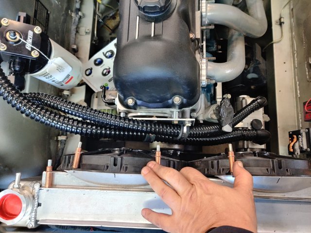
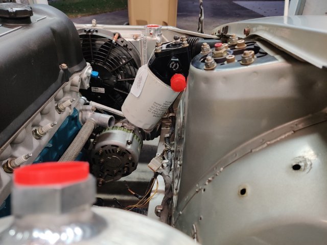
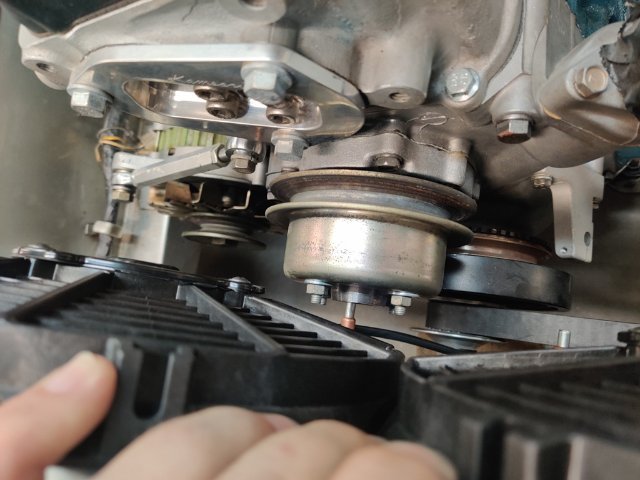
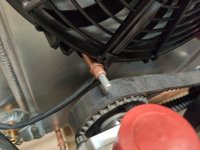
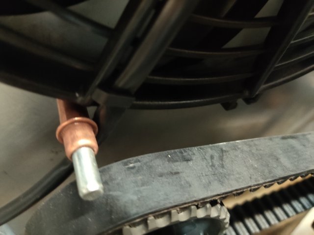
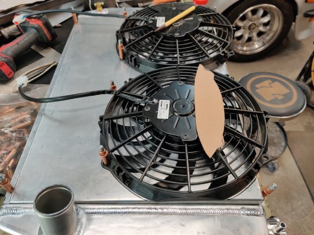
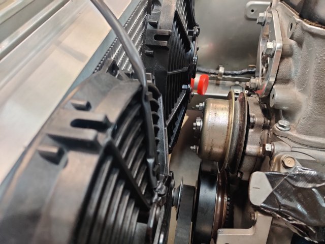
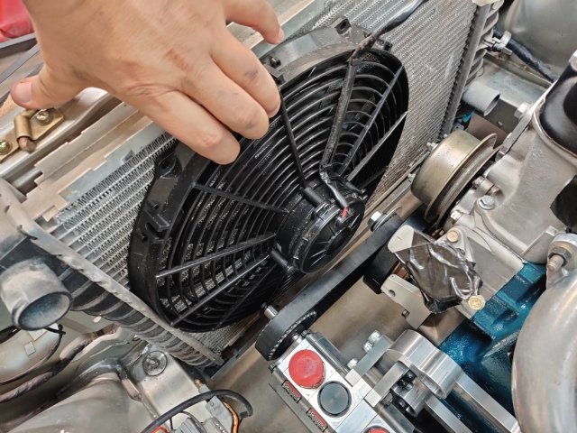
Progress today was slow because I ran into some further complications with adding a shroud along with the fans and radiator. Adding a shroud to my plan has made things more difficult. After much thought, I measured out and bent up a custom shroud. At the top, the shroud is spaced 1" from the fins. At the bottom, it is spaced only 1/4" from the fins. This was done to get a bit more clearance. So, it angles a bit from top to bottom. Additionally, I had to offset the fans so the top edge of them sits above the top edge of the shroud. This allowed me to get clearance at the oil pump belt. To cover the area where the fan extends above the shroud, I made a little aluminum extension. I plan to weld it to the shroud at the top. I will make another for the second fan and weld it in as well. At the lower part of the shroud, I will install some rubber flaps of some sort so that area will not just be a wall where air can't get through the radiator. I am going to replace the studs in the water pump (that hold on the pulley) with bolts instead. That will add about 3/16" more clearance to the fan. Additionally, I think I will need to put a strap on the inside of the shroud to strengthen it at the middle - this will be my attempt to keep it from getting pushed back (flexing) at high speed, and moving the fans closer to the rotating parts of the engine.
-
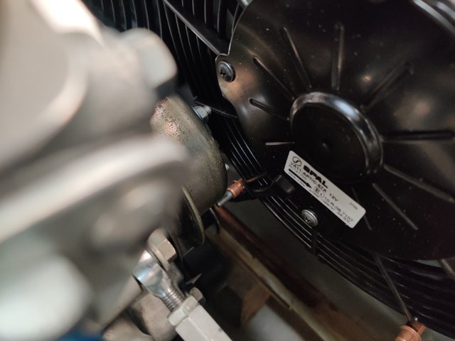
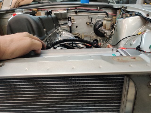
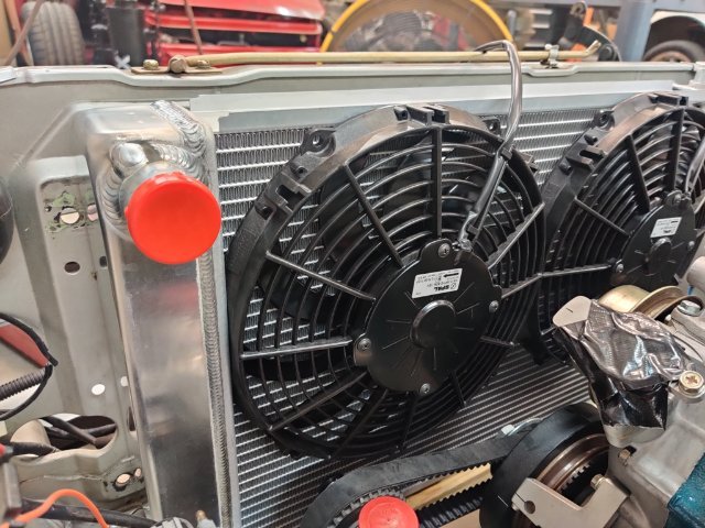
After lots of measuring and thinking, I ordered another Griffin radiator and two 10" Spal fans. This radiator is a bit wider and the same height as the other Griffin I bought years ago. However, the core has two 1" wide tubes instead of the two 1.25" wide tubes. Thus, the core is a bit thinner and that helps provide a bit more room for the fans. Being a bit wider, the two 10" fans fit better as well. Here are some pics: I will mount the fans at the top as shown. This will put the fans above the oil pump shaft and crankshaft dampener bolt. I will probably shorten the oil pump shaft, as the extra length is not needed for this application. The bottom edge of the radiator aligns with the bottom edge of this blue painter's tape. The side tanks fit just inside the stock radiator mount bolt locations: I am very pleased with this combination from a fit standpoint. Each fan is rated at 802 CFM. I repeatedly came across information where the CFM was higher when they were used in pairs in combination with shrouding. So, I plan to add some shrouding as well as some directing panels on the front to improve total CFM. I won't be able to measure it, but I think bumping the total up to 2000, an amount that should be good for a 6 cylinder engine, should be possible. Next, I will figure out how to mount the radiator, and wire up the fans.
-
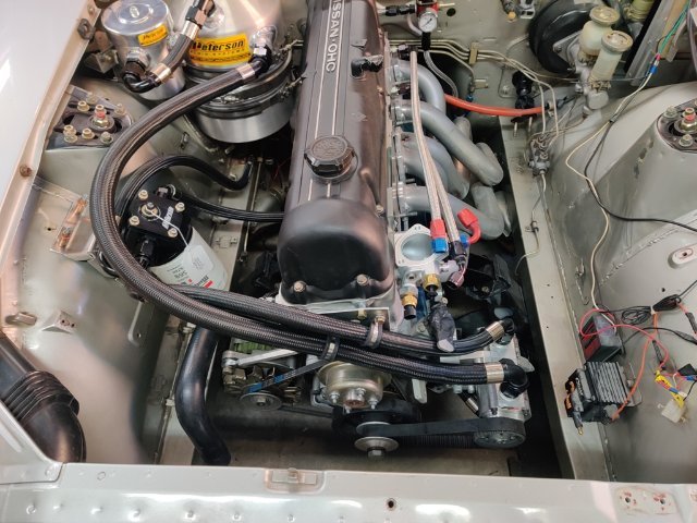
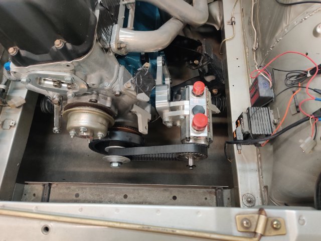
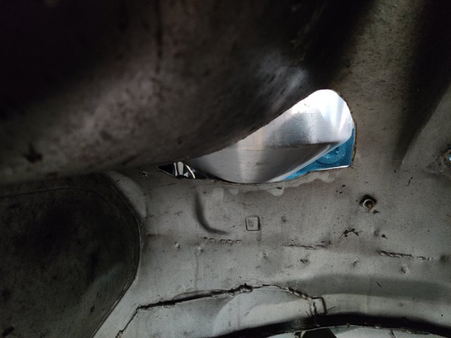
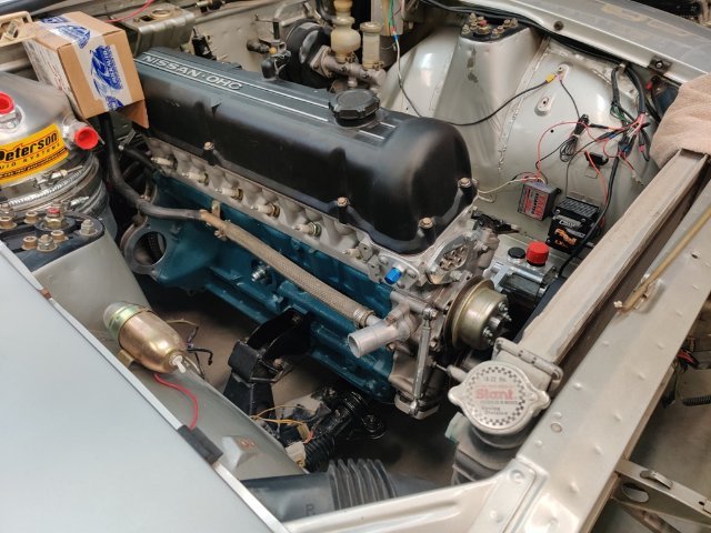
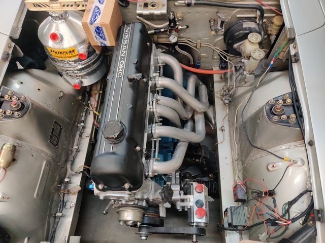
I put the engine in the car last weekend. This weekend I am doing a lot of staring at it and thinking. I need to figure out how and where to route all of the oiling lines. And I need to figure out what to do for a radiator and cooling fan as the Griffin I bought is 3" thick and is awfully close to the crank dampener bolt. Those are the immediate concerns. I still have to wire up and install a set of Speedhut gauges, drain and flush the gas tank and lines, and a bunch of other stuff before I can attempt to start the new engine. Going to put the tank about here: Have to cut sheet metal here to get the tank low enough to fit under the hood: Pump and custom mount: There is a good amount of space under the pan. I will route the two pan scavenge lines under here to the bottom two fitting on the pump. I can clock the bottom of the tank about 90 degrees to get the bottom fitting pointed towards the left side, and then I might be able to run a line from there, across the top of the transmission bell housing to the left side of the engine compartment, and run it along the frame rail to the front of the pump. Radiator situation - Griffin set in place in first pic is very close to the crank and oil pump shaft. The Stealth Conversions radiator is much thinner, but even some the 14" Spal would be a tight fit. And when I was last at the track with this radiator, the temp gauge indicated slightly elevated temperatures from normal. So, I'd prefer not to put that radiator back in this car for that reason. It was fine though for all use except track sessions in the August heat in Atlanta. I had no shrouding and a stock clutch fan (plastic) when it was last installed.
-
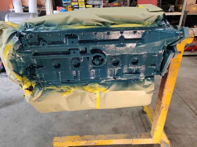
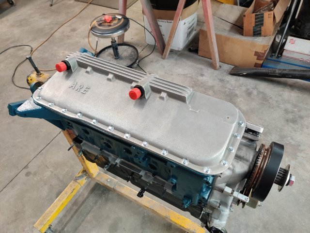
I have finally switched my focus to getting this car running again. This weekend I painted the engine block of the new replacement engine. I was hoping to get it in the car, but various things slowed down my progress. I thought I had a pilot bushing on hand, but couldn't find it. So, a trip to the store for that... Couldn't find the torque spec for the ARP flywheel bolts and wasted time looking for that. Little things like that eat time. Anyway, a few pics: With the back plate, flywheel, disc, and pressure plate now on, I am about ready to put the engine in. I think I will strip and repaint the motor mounts first. Then, I'll put the engine in and start the work to mount the oil tank for the dry sump. I will likely need to cut some of the inner fender well on the right side. I don't like going that route on my "early" Z, but I dislike blown motors more.