
Chickenman
-
Posts
1051 -
Joined
-
Last visited
-
Days Won
9
Content Type
Profiles
Forums
Blogs
Events
Gallery
Downloads
Store
Posts posted by Chickenman
-
-
14 hours ago, Timecode said:
OK, thanks for the tip.
Has anyone here experienced issues revving to 7k and the OEM bolt backing out? My current OEM setup hasn't given me issues backing out, my concern is with my old damper, which I feel will explode soon.
I'm guessing most who run an upgraded damper usually run the stronger bolt setup as well.
I know the stronger bolt allows more torque so less chance of the bolt backing out but is the OEM torque specs also accounting for the crank snout thread strength as well? Rebello told me a new OEM bolt/washer works fine and they do 20+ engines a month the same way with no issues.
Thread-lock companies say the bolt usually will break before the thread-lock gives way, hence my inquiry from others experiences. Typically, up to what size bolt needs heat to come loose without failure? I always use blue thread-lock but have little experience with red.
Yep... seen it on Datsuns, Toyota's, BMW's and SBC.'s at various Race Tracks. Happens more on Road Race cars and Rally cars than Drag cars. Extended high RPM's and secondary vibrations are the culprit. Kinetic energy and general destruction from a Crank damper flying off at over 7,000 RPM is NOT something you want to experience.
Edit. Red loctite on big bolts.The really critical fasteners that will result in death or destruction if it comes loose. Don't over use it. A drop or two is all that is necessary. You don't use High Strength Loctite on small fasteners because yes, you will snap them before the Loctite releases..
Proper Tools for the job. Proper strength Loctite for the job.
-
You would be amazed what extended running at high RPM's will work loose. I've seen Accelerator Pump screws on Holley carbs back them selves off. And base plate screws work loose then fall into the Intake manifold. happens all the time. I use a Medium strength Loctite on those. Never had a single failure while racing.
Rally cars have just about everything work loose if fasteners aren't Safety wired or use a Liquid retainer. Constant high RPM's and the pounding fro the roads and jumps took it's Toll. Guys who didn't Loctite everything or didn't use safety wire didn't finish Races or Rally's.
You don't have to slather the stuff on. One or two drops is all that is necessary. I use High Strength Red Loctite on Brakes and suspension mounting bolts ( Usually a larger size fastener ) and Medium ( Blue or Green ) Loctite on the small stuff. You can't always go by colors. So always check the product Technical data.
But I'll tell yah.. I've never had a driveshaft bolt or half shaft bolt come loose or any other critical bolt in over 35+ years of Racing and Rallying that was Loctited. I have had fasteners work loose that WERE properly torqued, had proper lock washers but Did not have Loctite or Safety wire applied. That only happened a couple of times before I learned my lesson.
-
Take it from people who have actually raced these things. Well before the Internet was ever thought of. Put the Red loctite on. Especially if you are going to push the engine at all.
Engine harmonics do bloody strange things. Nothing wrong with a little insurance.
I lost a $1,200 Tilton crank in 1977 dollars because a stupid engine builder ( not me ) used the wrong bolt on a Tilton Crank pulley. Tilton Damper had a thicker hub. Required longer bolt. Engine builder did NOT use Red Loctite. Probably would have held fine if he did.
And actually... bolts DO back out. That's wire Race cars also use Safety Wire. As do Airplanes. When your life is on the line you want to make damned sure that a critical bolt doesn't come loose from Vibration. Belts and suspenders every time.
-
 1
1
-
-
Thanks Tyler
")
-
BTW... that's the genius Mr Pearson himself making some final adjustments. You should see his Fab work. Thes cars are still State of the Art. And they were built in 1998 if memory serves me correct. Still the fastest cars in GT3 after 20 years.
-
I'll show you a picture of 4 Time SCCA National Runoff Champion Collin Jackson 240SX GT3 race car engine a bit later. Now these have to breath through a teeny tiny 38 mm restrictor on the engine to equalise HP. Andy Pearson, the engine builder at Specialty engineering can go Toe to Toe with any engine builder around.
Colin is the only entrant in SCCA history to have won every single SCCA Runoff he has entered. This year the SCCA Runoffs are in Sonoma. Where Coilin holds the track record. Dare we say 5 out of 5?
This is a KS24 12 valve Datsun motor... breathing through a single 38 mm " Straw"..... and it produces 280 crank HP. For a " Truck " engine that isn't supposed to be able to Rev or produce much HP... this is astounding.
There is s s**t load of work done to the Intake system and manifold. Including an absolutely HUGE Intake plenum Some very, very intelligent thinking going on here folks.
In the following photo... the 38mm restrictor is the black object just ahead of the Plenum. Look at the sizing of Plenums before and after the restrictor plate tube. You can't see the inlet of the restrictor tube, but it tapers smaller facing forward. Bear in mind that the Plenum Volume also includes the large diameter silver tube attached to the rear of the Restrictor Tube. So the complete Plenum volume is rather large shall we say. Part of a successful restrictor Plate engine.
-
I'll be doing this upgrade sometime in the future. Along with 100 other Projects I seem to keep putting off.
With respect to BRAPP, the restriction in the runners is not as relevant to TB sizing as people think. Importantly they are not looking at the complete operation of a Plenum manifold. Don't forget, ALL 6 runners have a combined flow that has to go through the Throttle Body. Any improvement on flow to ANY area of the Intake manifold will have an effect on the overall performance. Especially to NA plenum manifolds.
Adding a 60 mm TB and porting the TB opening won't give you much of a gain. But it is measurable. Removing the bumps at the TB intake definitely helps.
Adding a larger Plenum while keeping the same size runners also results in a Performance gain. People who do not understand how this can work with smaller runners need to look at the design of Plenum manifolds . There are formula's for working out the Plenum volumes. I don't have them at my finger tips. But for maximum performance the Intake plenum volume has to be much larger than the Volume of all the Cylinders combined .
The trick is reducing the Vacuum pressure drop created inside the Manifold. Ideally you want the Plenum and TB to be large enough to allow the Plenum to be at atmospheric pressure at WOT . If you are creating a Vacuum in the Plenum at WOT, you are reducing flow to the engine. This is true on any engine. Most factory manifolds do create a Vacuum at WOT.
Increasing Plenum volume and TB size do improve performance. Even with much smaller intake runners. . All you have to do is look at V8 EFI Plenum racing manifolds. HUGE Plenums with HUGE TB's. TB"s have a much larger flow capability than a single runner. Or even all of the cylinders together. It's all about reducing ANY restriction to flow through out the complete manifold, and also about keeping the Pressure drop minimised at WOT.
-
See Softopz on the Vendors forum. He's a Hybrid Z member and is a MegaSquirt and 14Point7 distributor. Plus he builds awesome Custom harnesses.
When you get it all ready to go, give me a PM. I do Remote Tuning and create Custom tunes for each individual cars, Very reasonable rates.
-
With Microsquirt you must use dropping resistors with Low Impedance resistors. It has no Pulse Width Current Limiting injector drivers to drive Low-Z injectors like the MS2 and MS3. Or you can use High Impedance Injectors of course
Personally, I find the Microsquirts has limited expansion capabilities. It's the cheapest for a reason. I would choose a MS2 assembled unit over a Microsquirt, especially on a Turbo car. Mainly for the expansion capabilities. But that's just me.....
-
Personally, I'd stay away from the Relay board. Many builders elect to design their own system using separate relays. . It gives you more Options in Power distribution.
Plus, the PCB board traces are a bit too small IMHO for high amperage Cooling fans and High Volume Fuel Pumps. Fuel pumps should be wired from the Battery with 12 gauge wire , through a 40 AMP relay and all the way to the Fuel Pump with 12 gauge wire. Ground side also has to be 12 gauge. The small PCB traces limit current on the Relay board. Weakest link in the chain deal.... just my .02c.
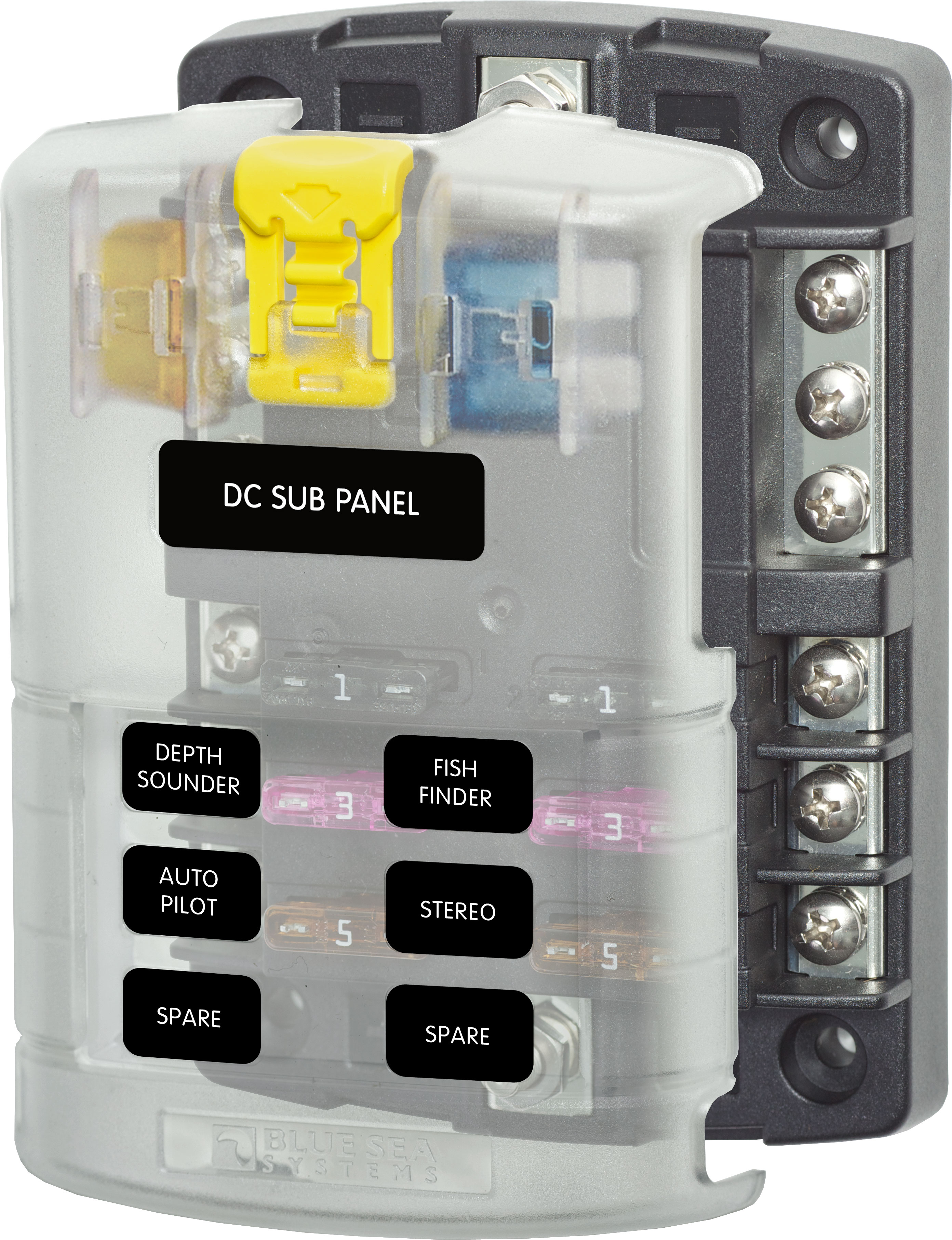
I like keeping all DC motors on separate Relays ( Fuel Pump and Cooling fans ) because they are danged noisy electrically. I put a Common Bus Fuse Box before the realays, and then feed the Relays off of that. Blue Sea makes some very nice Marine Common Bus Fuse Boxes. The Positive and Negative Bus models are very handy when wiring a standalone EFI system.
I wire it Battery Positive > Common Bus Fuse Box > Relays
#1 Relay = ECU and CAS/Hall sensors ( 30 amp Relay )
#2 Relay = Fuel Pump ( 40 AMP Relay )
#3 Relay = Injectors ( 40 Amp Relay )
#4 Relay = Cooling Fan ( 40 AMP Relay)
This method isolates the electrically noisy DC motors and Injector solenoids. The ECU and CAS/Hall sensors get their own Power circuit with clean isolated power. Use quality relays such as Bosch. The higher rated relays have larger contacts and are usually better made with Capacitors ( On Terminal 30 ) to cut arcing on the contacts.
https://www.bluesea.com/products/category/16/61/Fuse_Blocks/ST_Blade
-
I'm suspecting the MAP spike is in response to some other issue. It's a symptom rather than a cause.
-
Might be an idea to take screenshots of your settings and Export/Import your Tables. Then start a New project and Tune using the 3.4.2 defaults. The way you will get a clean build from scratch with all of the MS Extra 3.4.2 default settings. WUE, ASE AE etc. And you don't have to worry about signature mismatches.
-
Think I found the issue... at least with the Datalogs missing information. You are using an ancient Firmware on that ECU. Original B&G version 2.60. .B&G code is over 12 years old.
You should update your firmware to MSExtra code. Latest release version for MS2 is 3.4.2. Lots of improvements and bug fixes since the B&G firmware.
You update the ECU Firmware from within Tuner Studio. Choose " Firmware Update " in the Tools Menu. Your laptop must be online with your MS ECU and must be connected to the Internet.
Update your Firmware and reload your Tune. I would advise making a brand new Project file after the Firmware update to keep things straight. Otherwise you may have issues with file mismatches.
You will get a signature mismatch on your Tune when you update the Firmware . Easy to fix. Just make sure that you your Laptop is connected to your ECU and Internet at the same time. You will be given an Option to download the latest signature files. That will update your Tune Signature format to match the new Firmware.
Note: Do NOT confuse the ECU firmware update with Tuner Studio software update. Two different things.
Think of Firmware as a Bios update on your Laptop or Desktop computer and Tuner Studio software update as Windows/MAC OS updates.
-
What version of Tuner Studio did you Log with Free version or Paid version. Many selectable fields are missing. I wanted to see if you had any Sync loss. But the field was not viewable.
Did you edit out any fields from Data logging?
-
-
Q:
Is a fuel pressure regulator required?
Asked by QUINCY on March 24, 2016
A:Thanks for your question. This pump has a max output of 9 PSI, so a regulator would be needed if 9 PSI is more pressure than your carburetor is designed for. Many carburetors require 4-6 PSI so in many cases a regulator is recommended.
Summit Racing Answer - March 25, 2016
-
On 4/11/2018 at 8:30 AM, Alioli77 said:
My car has an airtex 8012sx fuel pump with no regulator as it just pushes 3 psi.
The specifications for the Airtex 8012sx shows it has an unregulated out put of 9.0 psi. Don't know where you got the figure of 3.0 psi from. So you do need a good FPR. That would explain your flooding issue with your SU carbs.
-
Quote
BIP373s on a MegaSquirt-II V3.0 or V3.57 – Single Coil
Hardware mods required:
- Jumper IGBTOUT to IGN to send to IGBT ignition coil driver signal out of pin 36 on the DB37. (not needed on a V3.57)
- Cut out R57 if fitted on a V3.0 (This won’t be there on my units, though.).
- Our assembled V3.57 boards, if not fitted for direct coil control, will have a jumper from JS10 to the center hole of Q16. Remove the jumper from the center hole of Q16, and reroute it from JS10 to IGBTIN.
- Solder a BIP373 into the Q16 slot, using a mica insulator.
Do you have the Jumper wire JS10 removed from center hole of Q16 and attached to IGBTIN ?
- Don't forget to change the little Jumper Caps on the 3.57 board
- Place the JP1 jumper in the 1-2 position.
- Place the J1 jumper in the 5-6 position.
I do wish MS would not use the word " Jumper " for a connecting wire.
This is a " Jumper " :
-
As Softopz and I have both mentioned. Use the MSExtra hardware guide. It has the most up to date information and methods. I also sent you the relevant sections to look at for wiring. That does NOT include section 5.2.2. Section 5.2.2 is for a VR sensor. You do not have a VR sensor. You have an Dual Optical Crank Angle Sensor . As stated in section 5.2.8 of the MSextra hardware manual, the Nissan, Mitsubishi and GM Optispark systems have to be built in a specific manner. And that manner is in section 5.2.3 of the MSextra manual. Not the Diy site.
Use section 5.2.3 . The Nissan Optical CAS also must have a +12 volt power feed. It's not a simple LED like a Petronix or Mallory Unilite. Lots of complicated circuitry in the Nissan CAS and it requires +12 volt power input.
The part that must be understood, is that an an Optical sensor or a Hall sensor can be wired through the Opt/in circuit or the VR conditioner circuit. Either method will work. The old method was Opt/in. But the VR conditioner circuit provides a clearer signal and is provides adjustable noise filtering which the Opt/in circuit does not. That's why it is recommended in the MSExtra manual. But the use of the VR conditioner was only available with the software revisions in Firmware versions 3.2.1 and later. That's why we keep saying to use the MSExtra 3.4.2 Hardware manual. Tuner Studio will work fine with your current settings and the Tune I sent. Once the missing components are added and things are wired correctly....
The term VR conditioner is badly named. It causes confusion as people think that it is only for VR sensors. That's not true. It can be used with any sensor. Hall, Optical LED, VR or points. A better named would be just a generic: " Signal " conditioner IMHO.
Your mainboard ( and Relay Board ) are wired wrong and have missing components. Install the Bip 373. Move JS10 wire to an unused output ( Maybe SPR3 or SPR 4 ) It looks like SPR1 and SPR2 are populated. Probably for PWM idle control. Hussein can advise better on that than me.
You need.
1: BIP373 coil driver installed in Q16. Jumpers configured and jumper wire for JS10 relocated.
2: + 12 volt supply to the Nissan CAS. Right now we aren't sure what it's getting.
3: +12 volt supply in Run and Crank position ( Ignition switch ) to your coil. Right now it has nothing. That's not gonna work.
Remember that the MS ECU controls most devices by GROUNDING. It doe not supply +12 voltage to injectors, ignition coil, fuel pump, IAC solenoids etc. Anything with a high current demand has to be supply +12 volts through a dedicated circuit or high current relays.
Hope this helps clear the muddy waters...
-
BIP373 = Yes
DIY Custom 54mm L28ET Trigger wheel = yes.
Connect Optical through VR conditioner = Yes.
The MSextra Hardware manual will have directions to build VR conditioner circuit in section 5.2.3. VR conditioner recommendation is an update since the DIY articles were written. There are links to specific VR settings that go into more detail. It's all in the MSExtra 3.4.2 Hardware PDF.
-
Make your life simple. Buy the BIP373 coil driver from DIYAutoTuning. It's a whole $8.50. Forget about the HEI Module.
https://www.diyautotune.com/product/bosch-bip373-coil-driver-mod-kit/
Also, use ONLY the MSextra Hardware manual. That schematic is old news..... as is mostly everything in the Mega Manual. MSExtra Team has been doing the firmware development for the MS ECU's since about 2006. Anything marked " Mega Manual ", is from original B&G firmware developed before 2006... so its' only about 12 years old. A lot of improvements have been made since then.
You should also use the VR conditioner circuit instead of the Opt-In/Opt-Out circuitry. The VR conditioner gives a cleaner signal.
Softopz recommend this method ( VR conditioner ) . He custom builds MS2 ECU's and also custom harnesses for the L28 ET and just about anything you want. He's in the vendors forum.
Please note: I'm not a builder. I know a fair bit about MS builds, but I mainly do Remote Tuning. Once you get ready to run I can help you out with a Baseline set-up and Remote Tune for fisrt start-up. PM me for details.
-
Have you posted this up at the MSextra.com Forums? Are you using the MS2 Hardware guide? Download it here:
http://www.msextra.com/doc/pdf/MS2V30_Hardware-3.4.pdf
Do not use the DIYAutoTune instructions. A lot of it is outdated material.
You need a high current Ignition driver to drive a single coil. That's the BIP 373. Waste Spark coil packs would need 3 x BIP 373.
Individual COP ( LS2 coils ) need the MS3X expansion board.
-
Socorob: If you lowered the car with springs or Coil overs. Did you shorten the strut tubes? If not you are probably running out of suspension travel and hitting the bump stops. Common problem. Then you have to put Box Car springs in the thing to keep it off the bump stops. Not ideal.
-
1
-
-
We all done similar things at some point with cars. At least there was some good discussion that came out of this. Now go out and enjoy driving the car!!

 Summit Racing Answer - March 25, 2016

l28et Damper bolt different than others???
in Nissan L6 Forum
Posted
Yep. That's pretty much my Rule of thumb also.