

cgsheen
-
Posts
672 -
Joined
-
Last visited
-
Days Won
8
Content Type
Profiles
Forums
Blogs
Events
Gallery
Downloads
Store
Posts posted by cgsheen
-
-
Ya, pics...
If it is a turbo harness, the only difference would be: the '81 harness has a 8-pin connector with a dropping resistor package (little aluminum "box") that sits just forward of the firewall near the master cylinder(s). The '82 & '83 turbo harnesses don't have that "feature"... What year is your ECU?
-
The 280ZXT ignition harness helps if you don't understand the coil wiring on these cars. But - as I've said multiple times now - you don't need the ignition harness. 2/3rds of the wiring is already there on the stock coil.
Plus it's not going to help you much - you don't have the turbo coil/ignitor.
What you need to understand about the L28ET ECCS system is: The ECU controls spark. The ECU sends the "signal to fire" to the Ignitor (Power Transistor), which amplifies the signal to a state that will cause the coil to spark. If you don't have a stock Ignitor for the 280ZXT, then you need a replacement Ignitor (Power Transistor, Ignition Module). Most people here use the GM HEI 4-pin if they're looking for a substitute for the stock Ignitor.
There are 400 posts in Z Forum-land about procuring and wiring a GM HEI. You'll need to ADD the "signal" wire from the ECU to whatever Ignition Module or Ignitor you end up using. The Black/White to your stock coil is Battery Voltage when the ignition is in the ON position. It'll provide power to both the coil and ignitor. The Blue wire can be used to drive the Tach if you disconnect it's connection to the stock electronic ignition module. It'll attach (or stay attached) to the "-" coil terminal along with the amplified output from the ignitor. If you don't understand that, have someone who does wire the coil and ignitor up for you...
-
Download the Factory Service Manual - 1970-1971 Datsun 240z Sport. You need the "1971 FSM Supplement". Get it at xenons30.com (an internet search of "1971 FSM supplement pdf" found it right away for me...)
It describes the entire heating/ventilation system and shows all of it's component parts. What you have there so far will make a lot more sense once you've looked over the Supplement.
-
So you'll be ready to join us on the Mt. Lemon run on the 15th?
-
Fairly simple actually, just make sure you get all the parts you can if you have a donor. You don't need the pedal box, just the 2 pedals and their associated hardware (bolts, springs, washers, bushings, nylon bushing for the spring end, etc.) Most people forget the clutch "hard line" (unless you want to use braided steel hose for the hydraulic line).
In the '75 that I trans swapped, I noticed the hole in the transmission tunnel was cut diferently. I had to cut the top of the trans tunnel for the manual shifter. The "pattern" is already there in the metal, you just have to remove some additional metal at the front. Speaking of: Get the boot bracket off the 260 (the rectangular ring that clamps the rubber "inner shift lever boot" to the top of the trans tunnel).
You don't need to modify the console, the auto trans parts will come out/off and you'll never know the auto was in there.
As for the transmission, simple swap. You'll need a clutch/flywheel package of your choice and then make sure the throw-out bearing collar is the right length for your clutch package. Don't forget to remove the flexplate adapter and get a pilot bushing installed.
-
Lucas was talking to our Fab Guy recently about this very thing. I haven't seen anything yet though...

He's ready to do suspension on his Z, so I'm keeping my fingers crossed.
-
Don't worry about the "Ignition Harness". If the stock coil wiring is still there in your 280Z you have 2/3rd's of the coil/ignitor wiring. The Black/White that ran to your stock coil will provide power to the ignitor and then to the coil, the Blue will still take signal back to your Tach, the coil/ignitor will be grounded to the frame, and all that's left is the signal wire from the ECU to the ignitor - just one simple wire to add.
-
700mm hg (top mark of the stock 280ZXT boost gauge) equals 13.535756611psi. Still, Tony is right - a working relief valve will pop-off long before you get to 700mm hg... (preventing you from getting to 700mm hg...) And, it makes a noise that's unmistakable! Everyone nearby knows when that thing opens - and wonders what the hell it is.
-
Like this...
-
C.A.S. signal wiring:
Green -> ECU pin 8
White -> ECU pin 17
The wire color changes in the ECCS (engine) harness at the round 4-pin C.A.S. connector. On the stock harness, it actually goes like this:
G -> GY -> ECU pin 8 (I'm fairly certain this = "one degree" signal (outer optical disc ring, 360 slits))
W -> GB -> ECU pin 17 (Is so, this = "60 degree" signal (inner optical disc ring, 6 slits))
Please note that some of the sensor wiring is shielded cable. The shield is to protect the signal from other electrical noise (interference). They use shielded cable for the CAS and AFM wiring.
-
)
2) Does this diagram look better?
No. The Black/White is NOT a GROUND. It's BATTERY VOLTAGE (power, +12V, juice...) (sorry I shouted...
)Black/White can be referred to as "Main Power" directly from the Ignition Switch, at IGN ON, +12V (which is technically incorrect as the positive voltage can vary greatly...)
"1) Theoretically I could just replace the relay with two manual switches that I have to switch on before I start the car, Correct?"
Correct, but in my view, that would be an even bigger PITA than finding a stock-ish relay and wiring it up like the diagram...
"3) I dont quite understand what you were saying about the HEI in the last couple of sentences in your post. Could you explain that?"
What part?
If you had an HEI in your hand, you'd notice that the the backside is a metal plate. And, the mounting holes have a brass ring on the inside. The HEI can get hot (the "power transistor") - hot can kill electronics. That's why many people mount the HEI on a heat sink (usually a finned aluminum box or plate - designed to pull heat from the device attached to it.). Search - there are many examples on the interweb and it's not just Datsun guys that use the HEI instead of the stock Ignitor...
The "HEI body needs to be grounded" is cautionary - the HEI itself gets it GND from the body of the module. Either the backplate or brass mounting rings need to be in contact with GND. If you don't mount the HEI directly to the car body or some other grounding point, you'll need to attach a ground. Easiest is attaching a ground wire on one of the mounting bolts while you're wiring the ground to the HEI GND spade (connector).
Otherwise the HEI (or stock Ignitor) is four simple connections:
1. Power
2. Ground
3. Input signal from ECU
4. Output signal to coil "-"
I don't care what color wire you use. I just think it's wise to follow the factory color scheme. Easier to trouble-shoot down the road and less confusing for you (and whoever else needs to work on that Z) sometime in the future.
-
Crap, while I was writing you copied the "ground from ECU" in your drawing... NO!
That's the B/W - power at IGN ON. It does NOT come from the ECU - it comes from the ignition switch. That's power to both the coil and Ignitor as I said above. Please change your drawing so this inaccuracy doesn't propigate...
(Just noticed you're from Tucson, tell Jon "Hi" for me.)
-
EFI Relay:
Personally, I would scrap the EFI relay you have pictured. It's a slightly complicated relay used in early EFI Z's and it confuses most people. For the L28ET you just need a simple 6-pin relay like they use in the stock 280ZX. (it's a simple 2-contactor (switch) relay pictured in you ciruit diagram above - an electromagnet or "coil" (when powered) closes the contacts (pictured as bars above dots in the diagram). When unpowered it releases the contacts and "turns off the switch"... One "switch" powers the Injectors and one "switch" powers the other ECCS components. (including the C.A.S.))
If you follow the circuit diagram: Power to ECCS comes from the battery, through a fusable link, to the relay. The relay is set by the B/W "IGN ON" power - so - one side of the relay coil is connected to B/W from the ignition switch, one side of the coil is connected to GND.
"Source" power to the "switches" comes from the battery through fusable links (on the stock 280ZXT that's a Brown and a Green going "in" to the relay switches). On the "output" side of the relay, one goes to power all six injectors (stock color is Red going out) and one goes to all of the ECCS components and to the ECU as shown in the diagram (stock color is B/W).
C.A.S.:
Correct, Red and Black are power and GND. Power comes from the EFI relay as mentioned above.
The White and Green are signal out to the ECU. One of the outputs signals every degree the engine turns, the other every 60 degrees the engine turns. (it's easy to tell if you have these wired backwards: pull the coil wire off the distributor. When you crank the engine it should spark frequently if you hold the end near a ground point. Wired backwards, you'll only get one spark every several engine rotations. Swap the White and Green and it'll spark like it should...)
I'll pull out my electrical meter and test which ECU pin the White and Green from the C.A.S. connect to. (one goes to pin 8, one goes to pin 17 - I'm dyslexic about which is which) I'll post that up later.
Ignitor (transistor ignition module, power transistor):
There are some inaccuracies in some of the links that describe both the stock Ignitor and the HEI module. The Ignitor itself couldn't be more simple. It's merely an amplifier. It takes a signal from the ECU and amplifies it to a value that will cause the coil to fire.
SO... It has a power input and a GND. It has a signal input from the ECU (pin 5 - Yellow(?) wire) and an output to the "-" side of the coil (normally Blue). Power to both the "+" side of the coil and the Ignitor comes from the B/W - you already have that from your stock coil. (Your Tach signal will also come off the "-" side of the coil)
If you use the HEI, the body needs to be Grounded and many people mount them to heatsinks...
In one diagram, it shows the B/W as a "Ground". NO! The B/W in this era of Datsuns is always Battery Voltage at IGN ON! Never assume the B/W is a GND!
-
Correct. You can't just replace an '81 distributor with an '82-'83 distributor. You also need the distributor shaft from the '82-'83... Welcome to the wonderful world of dropping the oil pump and properly installing the shaft that drives the pump and distributor. Hint: know everything there is to know about this before you start. Installing the shaft improperly will cause you enormous headaches.
-
We had a '75 280Z here several months ago. It was driven 4500 miles by it's Datsun Dealership Owner owner and then put in a Museum. It's the most complete / original Z Car I've ever seen. I'd never really seen original weatherstipping so we were all over it, checking out the seals. It's amazing how good the original door seals were AND how wrong Precision got the reproduction part... (the 280 doors closed with a finger, the seals were soft and pliable...)
I too checked out the Kia door seals years ago and found they're actually just a "side bulb" type seal that you can buy new at a slew of places. The Kia seals do have a 90 degree corner molded in - not quite as tight as the 90 degree on the Z, but close. With the "side bulb" I just make them start and finish at that tight 90 degree corner and cut the two ends at a 45 to mate with each other. There are 3 or 4 stores nearby that carry this type of weatherstrip. It's very common.
-
My last post got deleted in the latest site outage so I'll post this up again:
We've had a local machinist make us weld-on adapters that are 280Z specific. They're the correct size for the 280z / "Late" 260Z strut tubes. (The Stance-USA adapters are 2" and we have been boring them out for the 280Z) Plus, they're longer for the rear so they can be welded directly to the hub.
We may be having them make 2.0 inch (240Z / "early" 260Z) adapters as well - Stance-USA can't seem to keep them in stock...
-
The stock engine mount is still on the cross member (passenger side - only one in the picture). I don't see any other mounts welded in there from your picture. The transmission looks like it could be a Datsun tranny, but it's pretty hard to tell from the picture you took...
-
There should be lots of threads you can find on this particular question. My advice is: don't waste time with stock engine management in your situation. Start with something you can tune. Which? That discussion is endless.... Start reading.
-
I'll be sure to mention your comment to Greg and Lucas. Seems like this has been "back-burner'd"... I know they both plan on using a camber plate with integrated strut tower brace mount on their project cars but neither one of them have been working on that recently.
(In AZ, we do things kind of bass-ackwards: Summer is the time we get nothing done in the garage (too darn hot). We save all our projects for Fall, Winter, Spring...)
Otherwise there has only been modest interest (at best) expressed from the community for these. You'll probably be waiting for at least one of them to get serious about installing the suspension on one of their project Z's before they turn out that camber plate.
I do believe however that the integrated strut tower brace plate will be a direct replacement for the existing "vanity" plate.
-
I know I have an '81 ECCS harness. But, I think that's the only one I have left. I should have looked while I was at the shop today.
I'll check tomorrow and call you. -
I never thought I'd see this day! It's usually the other-way 'round!
-
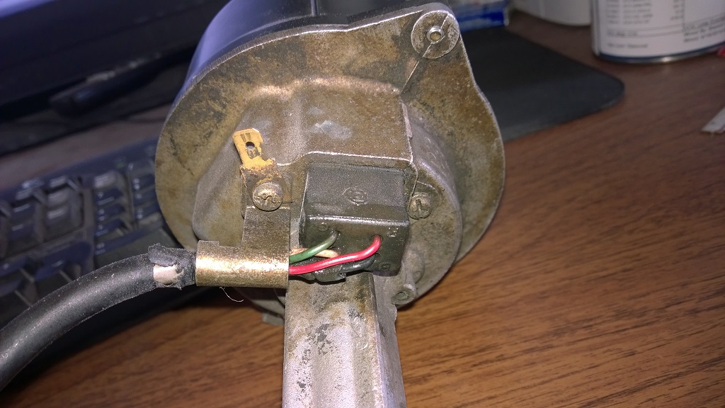
Yup, that's them. You may need to clean off the coating before you'll be able to re-solder and re-do all 4 to be safe.
-
Ya, if you're talking about a nissan optical module, I had the same thing happen. Turned out to be a broken solder joint on one of the pins (blades) that the harness connector plugs into. I had an intermittant drop out of the CAS signal to the ECU. I could have just replaced the optical unit but I resoldered all the pins and it's worked just fine for the last 2 or 3 years.
-
Even all the brake hardware - springs and retainers - are readily available. You wouldn't want to use the parts that should have been there anyway unless someone had already recently replaced all that. It's not much money to buy all new parts. Should probably rebuild (or replace) the brake cylinder while you're in there.
Oh, you're in the Philippines... You should just get TonyD over to help you with that.


 )
) I'll check tomorrow and call you.
 I never thought I'd see this day! It's usually the other-way 'round!
Harness years?
in Nissan L6 Forum
Posted
Yup, that's an '82-'83 harness and I'm pretty sure the ECU is also. Good Luck...