Barrel_Ball
-
Posts
83 -
Joined
-
Last visited
-
Days Won
1
Content Type
Profiles
Forums
Blogs
Events
Gallery
Downloads
Store
Everything posted by Barrel_Ball
-
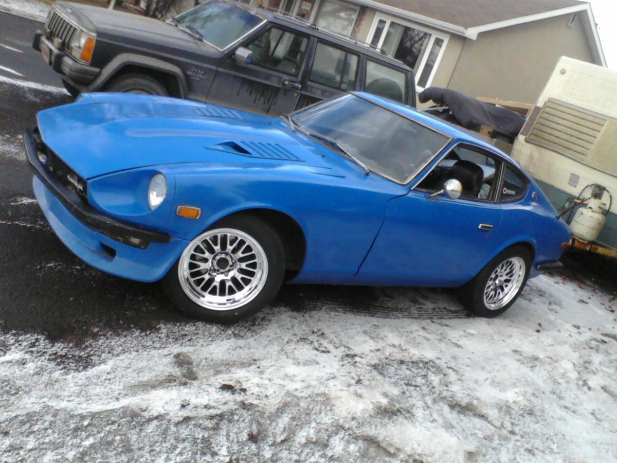
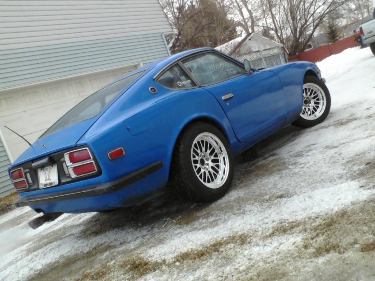
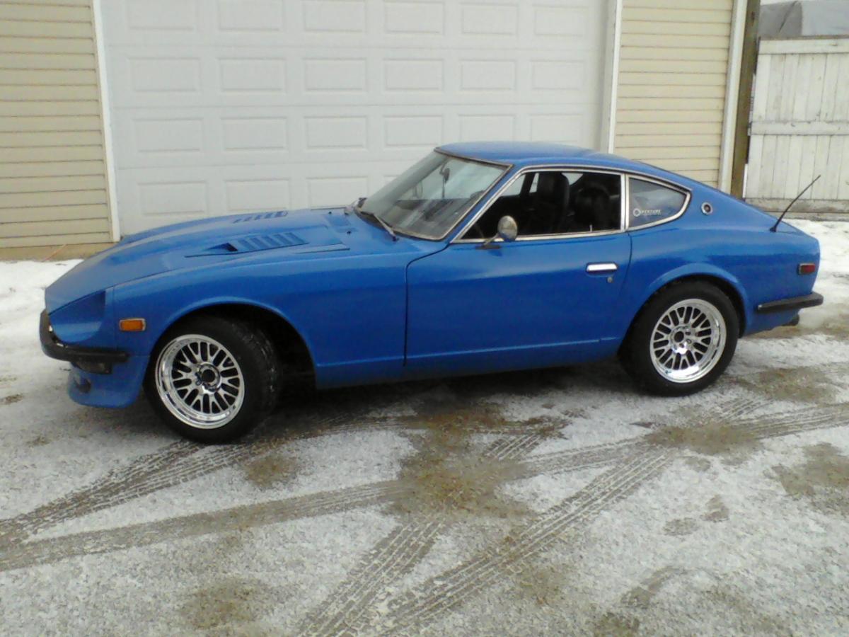
Finally got rims n' rubber on this beast. XXR 531's in platinum (16x8" 0 offset) wrapped in Falken Azenis PT722 A/S (225/50R16). Lookin' sharp!

-
Repainted mine last year. Need to go back and redo the roof and rear left quarter again since they're beginning to crack... Got a set of 16x8" 0 offset XXR 531's waiting for some rubber.
-

All three LED's on MS-II on solid at same time
Barrel_Ball replied to Barrel_Ball's topic in MegaSquirt
Okay, I reflashed it, and that didn't fix it yet, but when I replaced the fuel pump relay with a new one (they're cheap, generic relays), everything started to work again. Weird. Anyway, since I reflashed the firmware already at that time, I had to punch in my VE and Spark tables from scratch really quickly before the laptop's battery died again. I limped it over to my friend's place yesterday to return some tools, and adjust the timing. I still runs a bit rough on the low side, but it pulls hard under full load/boost, so it's working better than ever. And just as a preventative measure, I used silicone on the relay pigtails to seal the contacts from water damage. I don't want to leave the car in a mall parking lot over night again. This winter, I'm going to redo the harness again, and maybe get an actual relay board this time. Might actually have to sacrifice my glove box for it, but as long as it's all protected from the elements, that's all that matters at this point. -
All three LED's on MS-II on solid at same time
Barrel_Ball replied to Barrel_Ball's topic in MegaSquirt
Okay, so after some pulling apart and diagnosis, all I know is that my fuel pump relay burnt itself out by shorting 12volt live throught the whole thing I would assume. Now I'm going through the MS box itself, and I have yet to see a burnt component. I even traced pin 37 back (which is where the fuel pump relay's windings go to, and all it connects to is D4, a zenner diode, which then grounds through the board. All that's working. Is it possible that it's noticing that there's a connection problem with the relay that's supposed to be running the fuel pump, and error-ing out because of it? -
So I finally got my car on the road for tuning/driving a couple days ago, learned that ignition timing still needs some tweaking, and that I still need long enough vacuum line for the boost gauge. Anyway, it's been raining non-stop here in Calgary for the past couple days, and because of that, water got in my relay plugs (specifically, my fuel pump relay, no board here). This evening I pull it into the shop at my work to wrap the relays in duct tape to temporarily waterproof them until I can get a separate enclosure for them or something, and after topping up my tire pressures, I get in to start it, and sure, it cranks over, but it won't start. No signal to the coil, all three LEDs on the Megasquirt are on constantly. So I had to leave the poor thing in the shop overnight and walk it home this evening. Normally, the middle LED is on when the MS is on, and the bottom one blinks on and off at different intervals depending on the engine speed. I can't say I've seen the top one ever come on, or if it did, I probably wasn't paying attention. So if they're all on solid at the same time, does this mean I did something wrong? If so, is there anything I can do to find, and fix this issue because I hate the idea of driving my underpowered 4x4 all summer! P.S. Sorry for the wall of text. Also, I would've logged the situation as it happened, but the battery on my laptop died around then. Bad day...
-
I see, that's good to know. I suppose that means I'll be using my ol' laptop alot this summer. Probably put it on the road next week, since I only get wednesdays off, and the insurance/registry places are only open weekdays here. Anyway, it's been a slightly frustrating, yet very-worth-it experience so far. With this setup, I can say I worked on nearly every aspect of how the car runs. Once it's driveable, it's on to bodywork, and maybe a bit of racing. Thanks for the advice folks. I hope I don't break anything here, so wish me luck on the tune.
-
Oh... I believe I forgot to mention that I'm only using TS-MS lite, so the VE Analyze function doesn't work. But I guess a few trips around the block or up and down my back alley should give me a better idea of where I'm at. Looks like another week of doing nothing until I can get a registration code...
-
So I finally got the system to work enough to start the engine, and I put in the old metro VE/spark tables as a starting point. Problem is, whenever I try to rev the engine, I see the A/FR gauge hit somewhere around 10.9-11.2, which I'm assuming is way too rich. Just wondering if there's any kind of changes I should make to this thing to make it work better. I had to us the MS-II extra code since it was the only one that would let me select the proper trigger settings. Because of this, the VE table is a 16x16, but I just used the 12x12 numbers, and set the other 4x4 columns to higher values that the engine won't reach anyway. Here's the attached msq for tunerstudio. Got any ideas? 280zt 051811.rar
-
Huh... Yes, you can call me an idiot now. turns out, there were some jumpers I was supposed to make here on the PC board: XG1-XG2, OPTOIN to TACHSELECT, and TSEL to OPTOOUT. Can somebody tell me if this is correct for our application, or is it different for ours? Again, something I accidently skimmed past, and missed entirely.
-
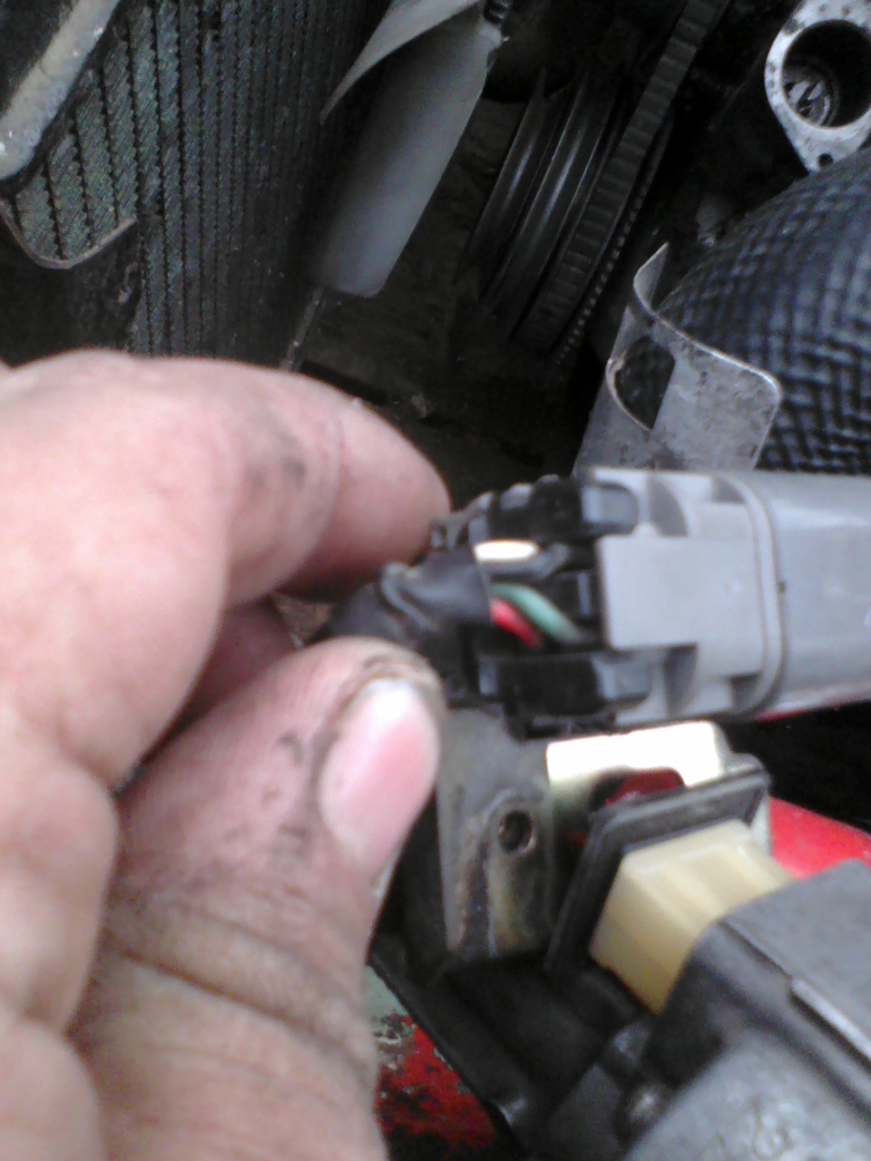
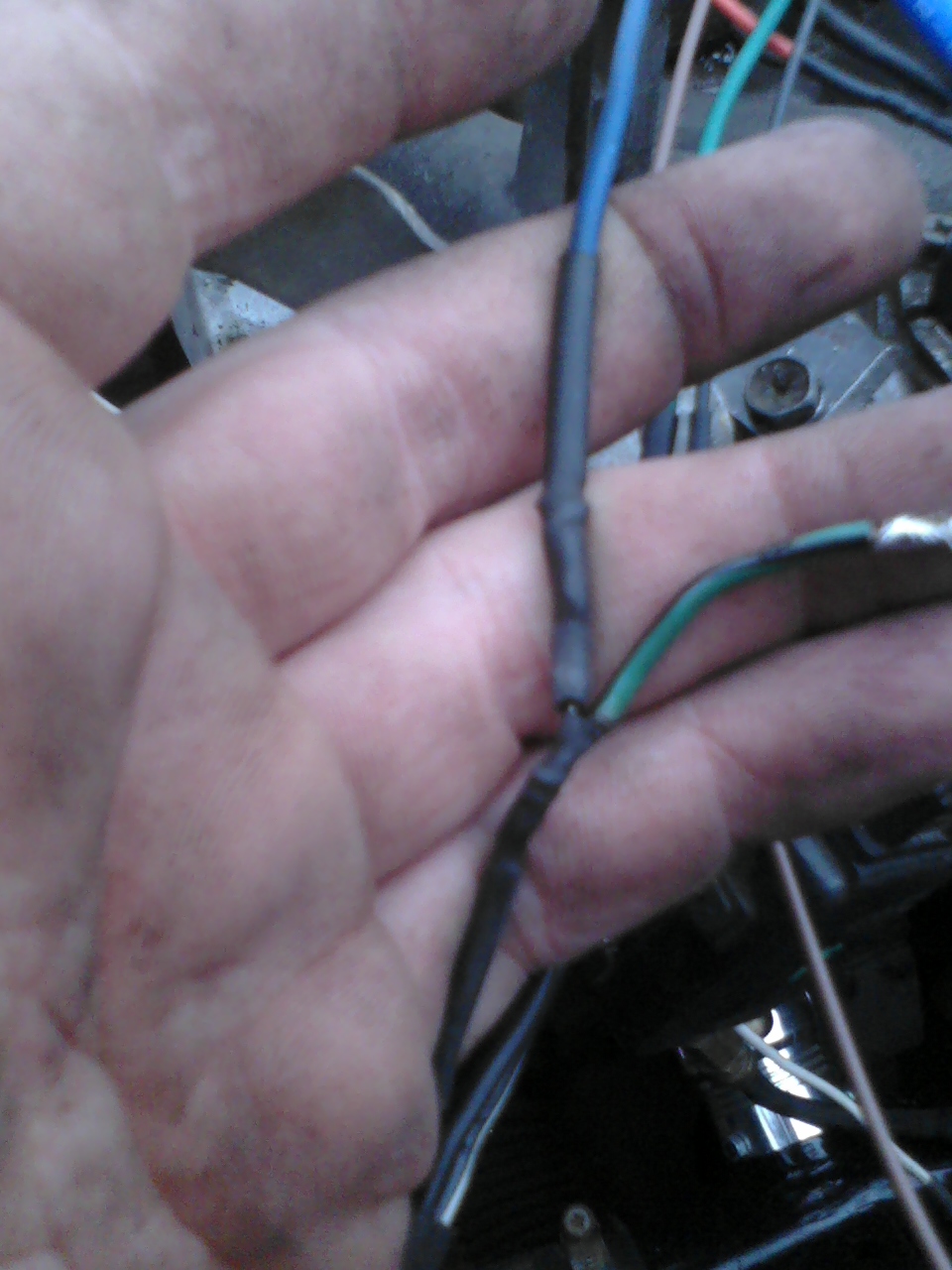
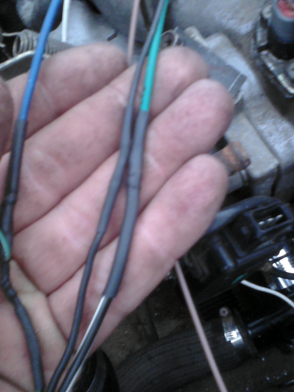
I finally had a chance to check out TS lite's logger feature, and I'm getting nothing from the sensor even still. Now I'm even confusing myself. I even stripped away the IGN wire's heat shrink to make sure the shielding wasn't touching the rest of the wire. I got pics here of the wiring in question. in the pigtail pics, Green/Black (harness side) goes into White (dizzy side), and Black/White (harness side) goes into Red (dizzy side). The 'Y' shaped junction is the Green/Black going into the IGN wire on the MS harness, with the Blue wire coming from a switched 12V power source. there's a 1K ohm, 1/4 watt resistor in line where it joins in this junction - you can't see it because it's covered in the heat shrink tubing. In the last pic, Green wire from 12V switched source goes into Black/White wire, while the solid Black goes to ground all the way from the dizzy. As stated before, my multi-meter sees voltage changes with this setup as I turn the distributor, yet for some reason, MS-II doesn't see a hint of it. Also, no, I don't have a stimulator to test MS-II with, yet I'm kind of wishing I had the cash for one at the time, so I'd be done with trying to get it all working by now. Edit: I just reviewed R57 in the megamanual: It says to not put anything there on the v3 board since it "creates problems" with the VB921/BIP373. Mind you, they're also talking about a 47K ohm, 1/8 watt resistor, too, so I don't know if using a 1K, 1/4w resistor will make a difference or not. I don't want to short something out by accident.
-
EDIT: I reflashed the firmware - It now runs MS2 Extra 2.1. Now I got the proper ignition menu, so I set it to basic trigger, rising edge, inverted. Still nothing. Weren't there some small potentiometers inside that one would adjust to make it work or something? I saw another thread regarding something like that, but I'm not too clear on it yet.
-
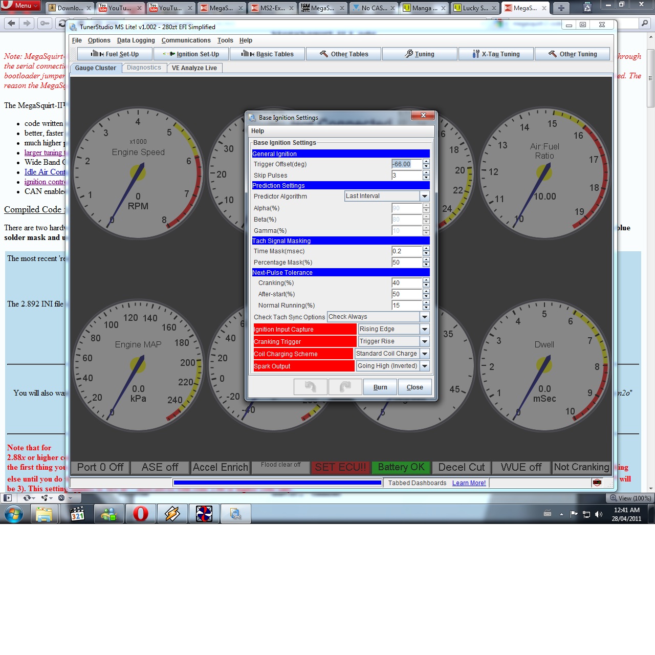
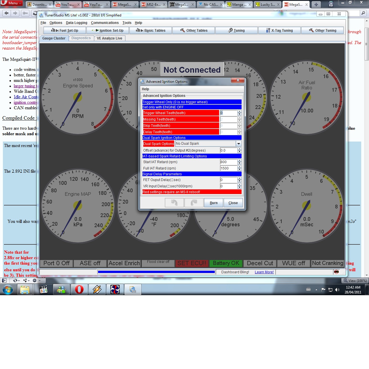
Wow, that looks a bit different than the supposedly same version of TS lite I'm using. Here's the ignition menus I end up with... Is there some sort of .ini file I should've added to a Cfg folder or something?
-
Okay, I looked at tunerstudio for a bit, and noticed that it doesn't have a trigger setup option either. I see no way in either program to set what trigger type I'm using. The base ignition settings just start with trigger offset, no spark mode or anything. If I missed something, I'm open for suggestions.
-
Huh... That's news to me, since that's what the tutorial site still recommends. Guess that's what happens when I enter the fray late in the game. Okay, I'll try the free version and see how that goes, since I don't have a credit card, and I never used my paypal so I don't remember my password... hehe...
-
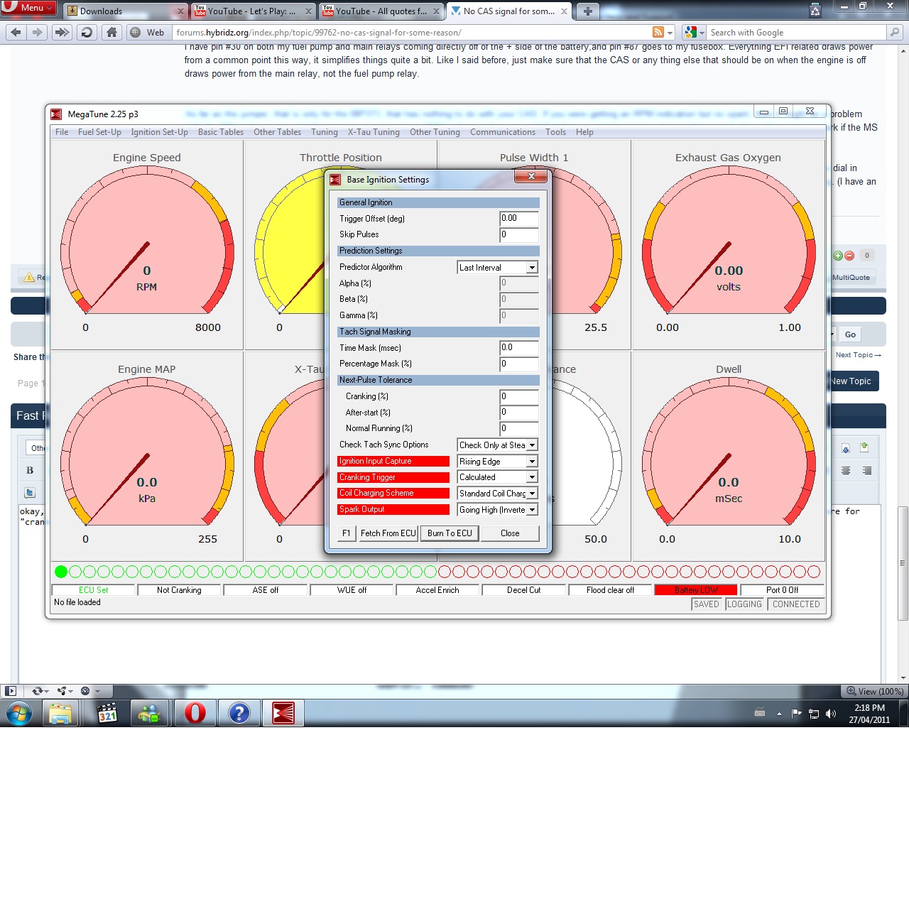
okay, so I guess the rising edge I didn't set, but where would I find the basic trigger? All I see for 'ignition trigger' in the 'basic ignition settings' window are for "cranking trigger", with the settings: 'calculated', 'trigger return', or 'trigger rise'. The attached pic shows the only ignition setting window I know of besides the timing table.
-
Okay, so I tried a few things like was suggested in the above post, and the CAS is getting/sending power/signals, the coil's getting power, even from the factory wiring (I disconnected the FP relay wire from the coil to confirm that). My only guess is there's a Problem with the MS-II, either hardware or software... Also, is it natural for the MS-II to sometimes keep the ignition system energized when the key is off? EDIT: Here's a pic of the assembled board. Did I do the jumper right for MS-II, or is my reading comprehension really that bad?
-
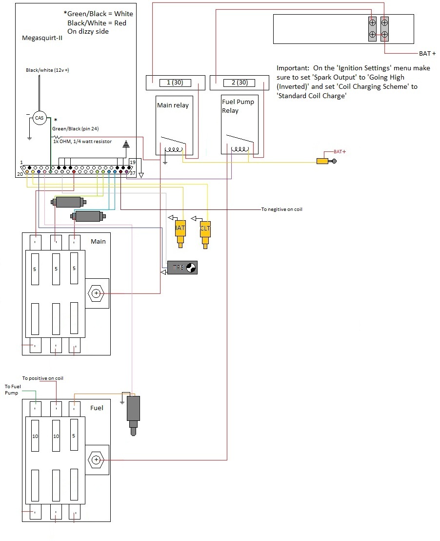
Well, I just used a test light on the plug going into the CAS, and the main power wire to it, which is the Black/White -> red wire, coming from the Main relay, is getting power. The test light won't get anything from the resistor wire, which is also the signal wire going into MS-II, since I would assume that thing is pushing miliAmps at this point due to the resistor. Even the ground is hooked up properly. I even got my wiring schematic made up here, and it's based off all the other diagrams I've seen. I wonder if the sensor finally kicked the bucket, but I don't know how that could happen...
-
I'm in the process of getting my Megasquirt 2 (V3.0 board) to work on my turbo '76. Pretty much stock internals, N/A cam, 10psi boost last time it ran, stock everything else on the engine for the most part. Here's the problem: The CAS ('82/83 turbo dizzy), isn't giving out a signal. LED on MS-II isn't blinking, no tach signal in Megatune, no spark off the coil, nothing. I did the IGBT jumper mod on the DIY site (using the BIP chip), and wired the CAS as the diagram said, with the resistor even. Is there some setting in Megatune (matches firmware v2.892) that I need to turn on for this to work? Ignition settings I put in are 'standard coil charge', and 'inverted/going high'. That's all I saw in the menu... Seems like every other setup I see is on earlier versions of Megatune that have different menus/tables. Any kind of help would be greatly appreciated.
-
Looks like your project is coming along really well so far. I'm curious about what the turbo and exhaust manifold look like. Keep up the good work.
-
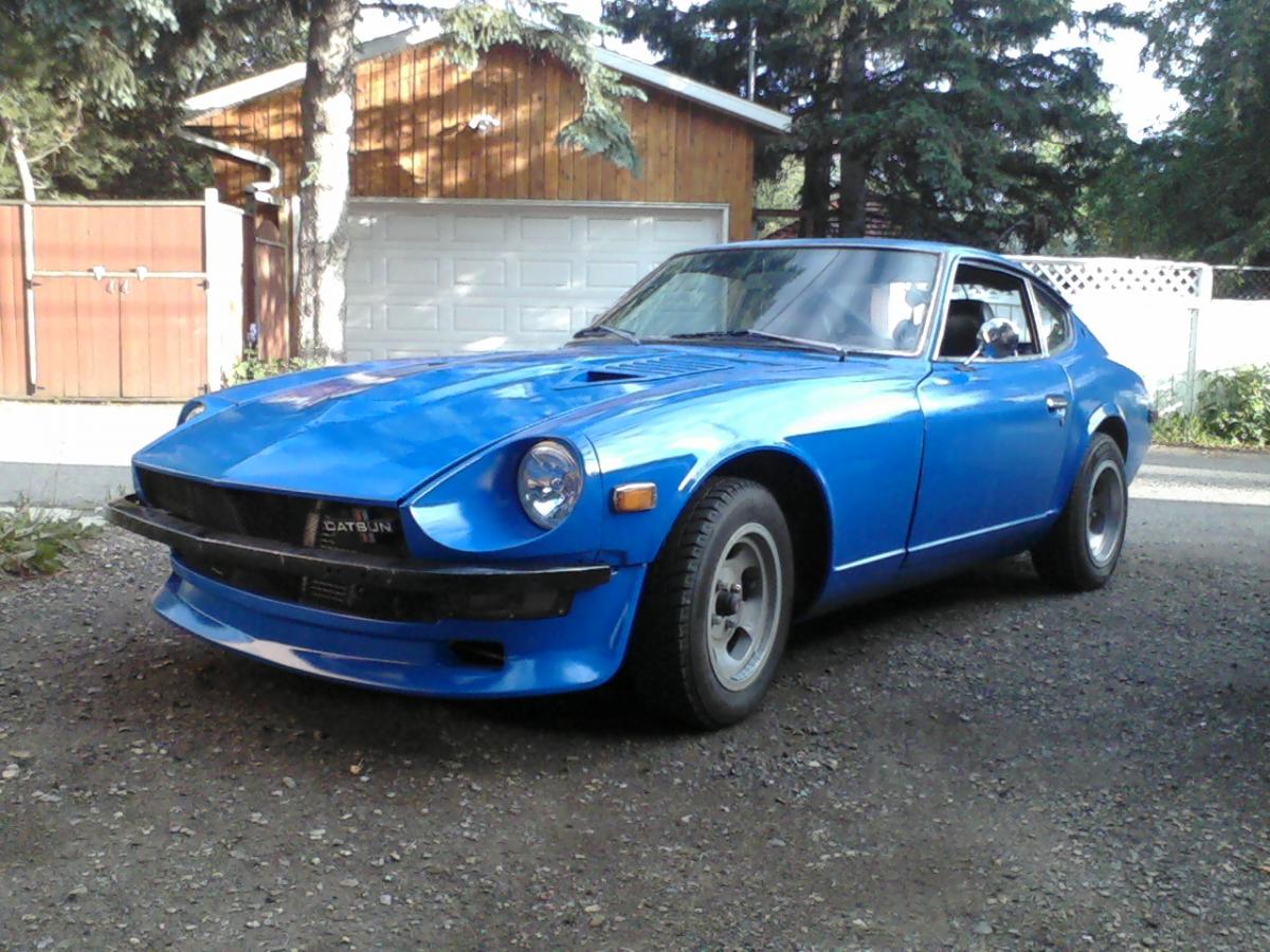
I had to have been 5 at the time, living in Mississauga, Ontario. We lived on a little cresent street where on the inner corner, I saw two 1st gen Rx-7's (little did I know I'd have one as a first car, but that's neither here nor there), and on ther outter side of that street. I remember walking by and seeing an open garage door at some guy's house, in that garage, parked facing inwards was what I thought at the time was a Pontiac Beaumont (the quarter window shape looked similar), but there was a few things amiss. I got my Dad to walk down the street with me to see if he can tell me what the car was. At this time, the car was sitting in the driveway, incomplete, obviously a project car. My Dad saw this and said "Oh, a Datsun 240Z. I used to have one of these.". From then on, I went out of my way to learn what these cars were, their history, their specs, their aftermarket, their signifigance in the automotive world. when I was 19, I saw a '76 2+2 sitting in a driveway in my area (I live in Calgary, Alberta now) with a 'for sale' sign in the rear window. I bought the car and a rusted out 240 for $300 with the intention of just swapping the drivetrain from the 2+2 into the 240, but I learned that both cars were beyond repair. Then, a certain Z club guy emailed me from one of the forums I posted on at the time, saying that he knew where I could find a decent project car - turned out to be his house! 1976 280Z 2 seater - Purple, white stripe, paid off for $3000 in early '08, got running with '76 2+2 drivetrain in June of '08. I'm turning 22 in a couple weeks, and my car already has things like the Toyota brake mod, L28ET swap, and soon, Tokico suspension, amongst other things in the near (or distant) future. I own a Z, and am dang proud of it.
-
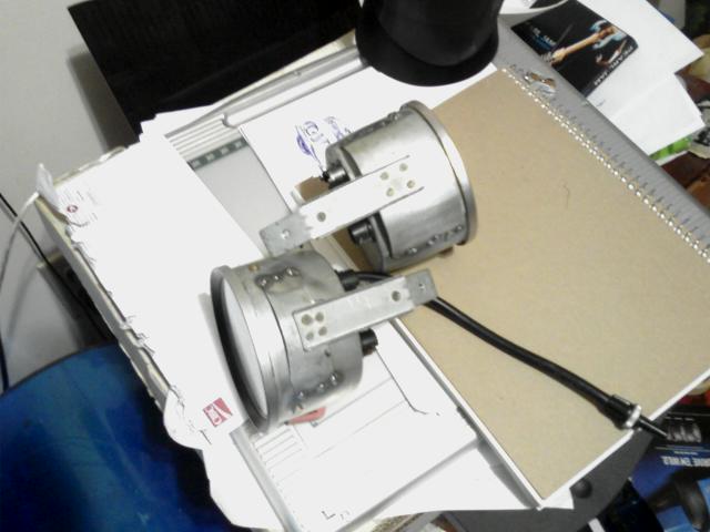
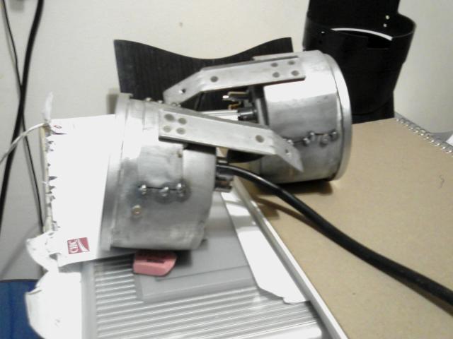
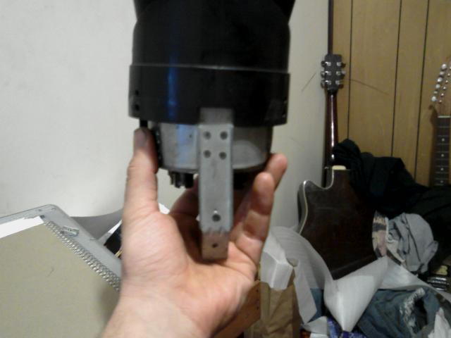
Found these gauges today
Barrel_Ball replied to Barrel_Ball's topic in S30 Series - 240z, 260z, 280z
Okay, so the 'resistor' replacement trick didn't quite work, but I came up with a proper solution. I had a tach from an XJ6 sitting around, so I used the circuit board from that, and soldered it to the XJ12 unit. Hooked it up today, and it works perfectly. Also, the two big guages are installed in the car now with brackets welded to the cans made from the stock gauge cans. All I need now is a proper fitting speedo cable, which I'm sure I can have made at a shop or something. I'll post pics of the gauges installed with new LED backlighing working next time.
-
Hey folks. Can anybody tell me even approximately what length the driveshaft for a 280ZXT T5 swap for a '76 280Z with a stock diff needs to be? The shaft I have with the proper ends is a 2+2 unit, and is waaay too long, so I figured I'd have a new one made using the ends to this one, but I need an yolk center-to-yolk center length and I have yet to find an answer. Any help is appreciated. Thanks.
-
Found these gauges today
Barrel_Ball replied to Barrel_Ball's topic in S30 Series - 240z, 260z, 280z
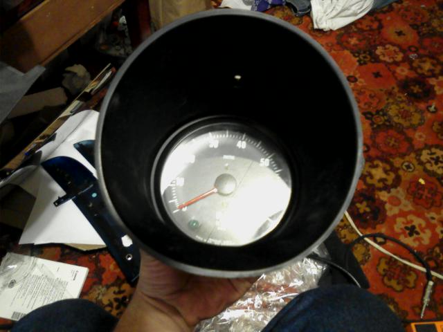
So today, I decided to do a little experimentation, and de-soldered that striped component (which I'm positive is a resistor of some sort) and soldered in a 10K potentiometer. I then, pulled out my stock tach, and hooked up the wires to the Smiths unit, fired up the car, and notice that it works. However, it only runs up to about 3500 RPM then dies off a bit. I have the red wire with the female bullet connector on the bullet male of the tach, the green wire on the spade, and the black wire on the ground of the tach body. I know I'm close to getting this to work properly, but I still think I'm missing something here. I pulled open the stock Z tach, and noticed that the ground wire also goes into the tach circuit. I wonder if I need to use that black wire on the same terminal as the green one? Since it might just be a second signal wire, but I'm not 100% sure. -
Found these gauges today
Barrel_Ball replied to Barrel_Ball's topic in S30 Series - 240z, 260z, 280z
I suppose you're right. I guess that a couple of alternatives would be to either A: Use the circuit board from a 280 tach, or B: Just find a way to adapt the face of the Smiths unit onto the 280 tach. Also, I just found an XJ6 tach at the junkyard today (who'da thought another one would show up!), but the stupid thing only goes up to 5000 Rpm before it redlines, so I'm not sure I could get that to work on my engine, unless I somehow solder that 6 board onto the 12 tach. Guess I'll have to take another picture - this time, of the 6's board... -
Found these gauges today
Barrel_Ball replied to Barrel_Ball's topic in S30 Series - 240z, 260z, 280z
The car I salvaged these from is a '77, which had the Lucas fuel injection, and I don't think I'm going to go and switch out all my wiring to run a V12 with that setup. In fact, just to rebuild these engines is expensive as it is. I just want to use the gauges with my car, which I think is possible. The place I work at deals with Subarus and Jags, so there might be a technical manual there that might have the schematics on an old smiths tach, but alot of their older books hidden in locked cabinets. Also, if what I think is a resistor is, in fact, a capacitor, what's with the stripes? I've never seen a striped cap before in my life - Not even in older stuff.