Barrel_Ball
-
Posts
83 -
Joined
-
Last visited
-
Days Won
1
Content Type
Profiles
Forums
Blogs
Events
Gallery
Downloads
Store
Everything posted by Barrel_Ball
-

1978 280Z (project name: Mothra)
Barrel_Ball replied to Barrel_Ball's topic in S30 Series - 240z, 260z, 280z
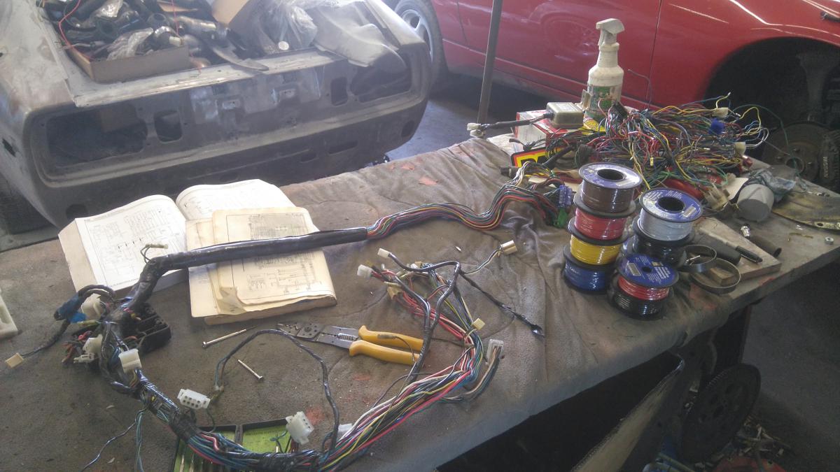
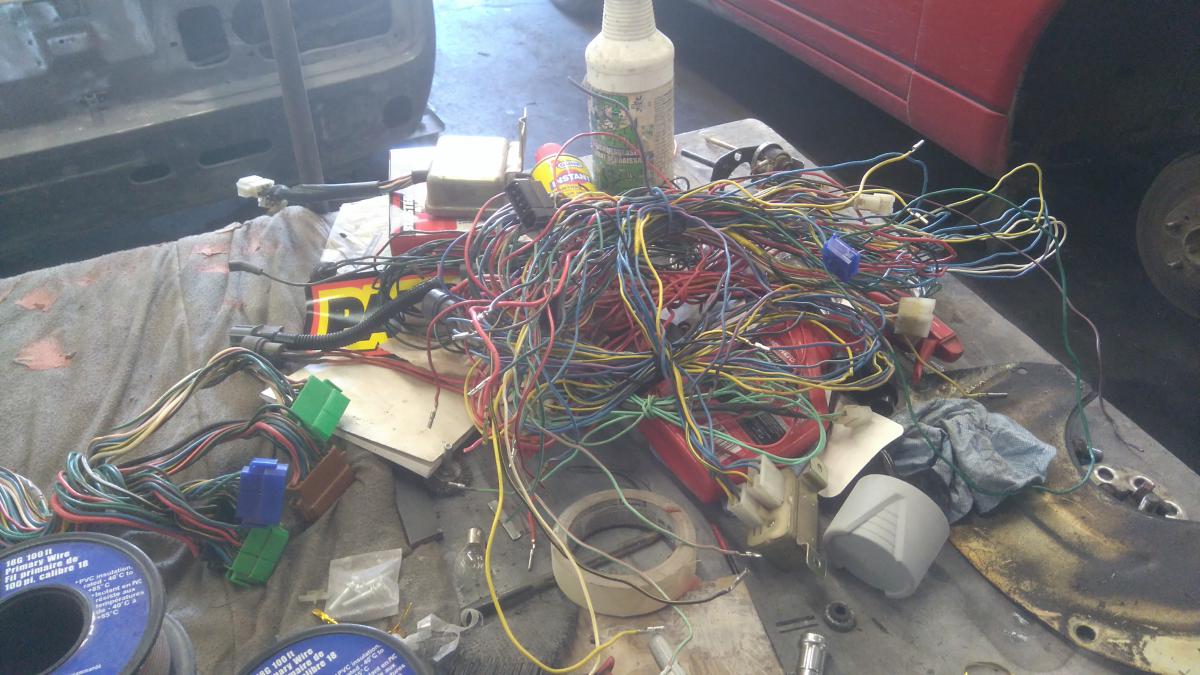
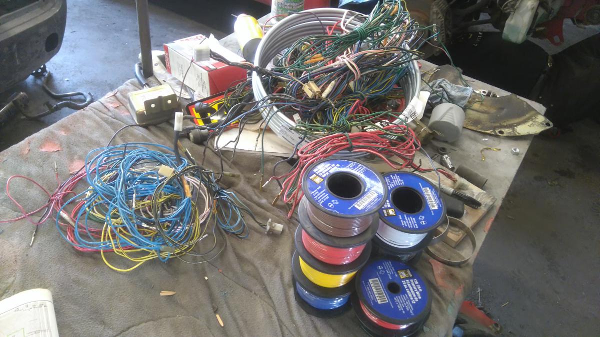
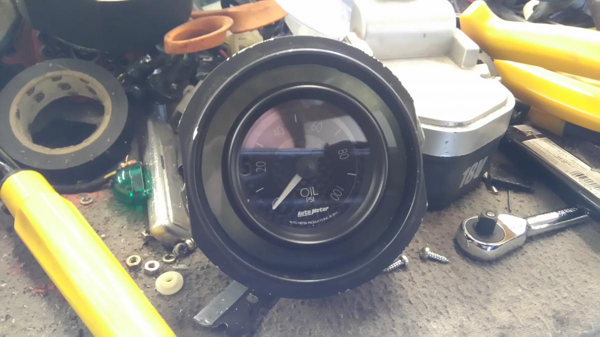
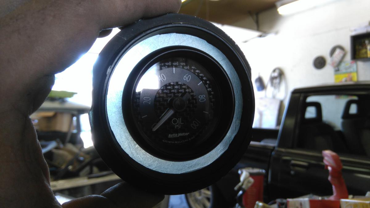
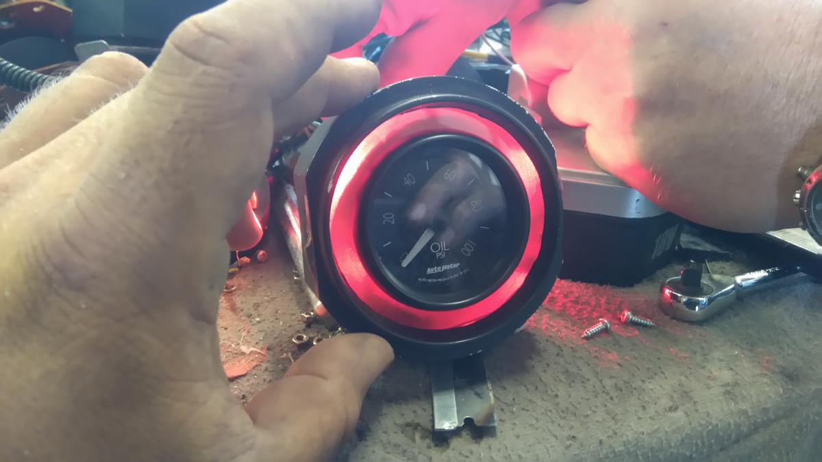
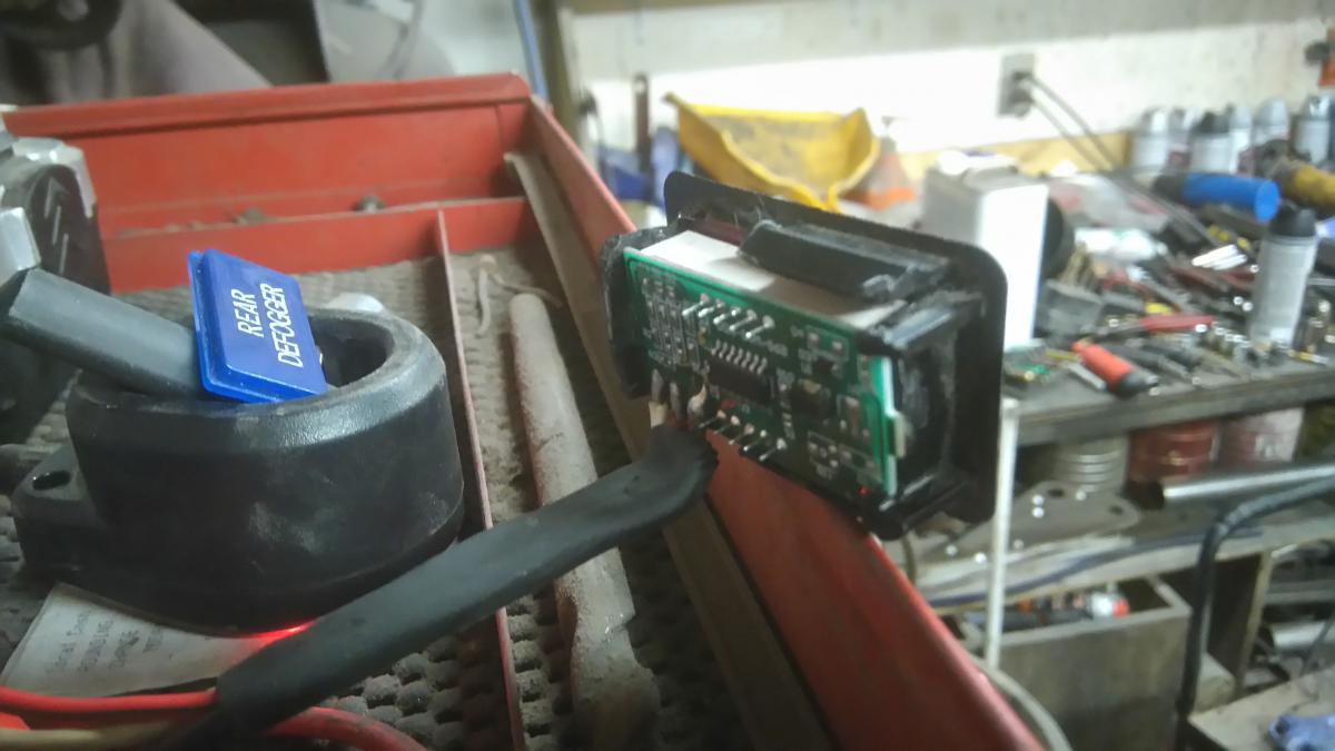
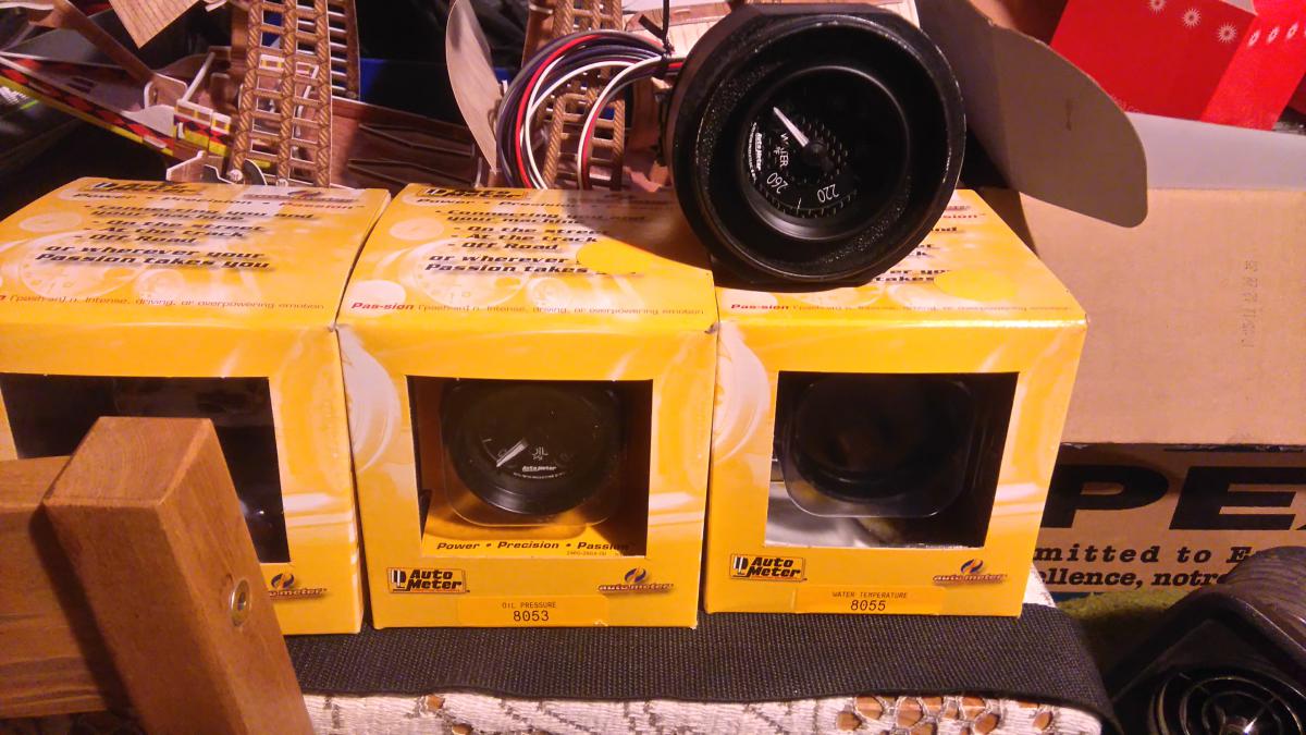
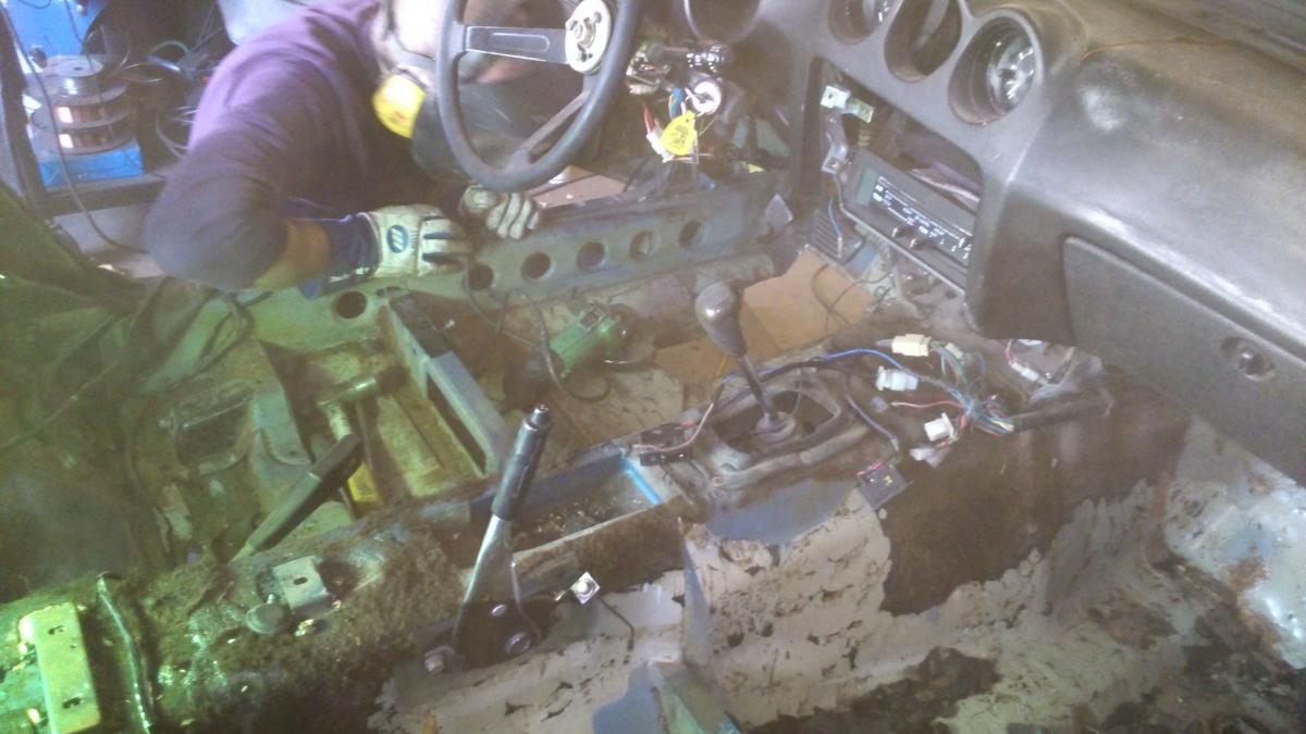
Project update. While stripping all the unnecessary stuff out from the front half of the car's wiring, I noticed some damage, and other crap on the back half, and decided "ah, screw it." and now we're re-wiring the car, bumper to bumper. Some of the harnesses on the table. Rainbow spaghetti. Lots of work to do. Then, the fun, experimental moment! When I bought my little 2" Autometer GT's, I already knew, going in, that they were not going to have any dummy lights of any sort, and seeing as I was going to drive this on the street, diverting my attention away from the road to look at a needle position on a certain gauge would be distracting, mainly in heavy traffic, where most people don't know how to drive. So I was tossing around some ideas for indicator/warning lights for the limited space I had in my dash. Then an idea hit me upside the head... Same installation method as previously planned, but this time, with tinted see-through acrylic, instead of opaque. Roughed up on the back side to break up the light. You know where this is going... And there. A "low oil pressure" dummy light. Soon as you see that red ring of death, you shut down that engine. Will plan a yellow one for "low fuel". Also decided to put in a digital volt-meter. Uses the old rear defog light bezel. Cheap and compact for the most part. Installed in center console. More to come.
-
L28ET custom exhaust manifold experiment
Barrel_Ball replied to Barrel_Ball's topic in Nissan L6 Forum
We're working on a support bracket for the turbo, most likely going to hang it off the intake manifold, since that seems strong enough. When I get in touch with my friend who TIG'd it together for me, I'll ask him about putting in some slip joints. Like I said, it's gotta come off for ceramic coating, anyway. -
L28ET custom exhaust manifold experiment
Barrel_Ball replied to Barrel_Ball's topic in Nissan L6 Forum
Could I get away with making my own slip joints, or do I have to buy specially made ones from Burns? Do they have to be an interference fit, or should they be able to move freely? Would a single slip be adequate, or is a double slip joint required? Suppose I put them just off the flanges where they bolt to the head? Or would they pull too far away and cause leaks? I'm new to slip joints on a turbo manifold - Only ones I've seen are leaky ones on N/A headers. Sorry for the gratuitous questions - I'd rather this stuff didn't fail at all, and some mechanic friends are telling me I'm thinking too much about this. -
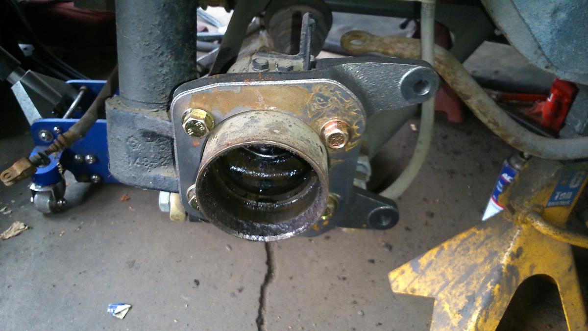
If the drive shaft is spinning, and the car is not moving, then the problem lies with your diff, and/or its connection to the wheels. I recommend you remove the diff from your car, put it on your work bench remove the back cover, and turn your pinion (input) flange, preferably while trying to hold your stub axles still. This will let you see if even your pinion and ring gears are meshing properly (they probably do, but process of elimination), and will allow you to see if your stub axles' splines are engaged with the inner bits of the diff. I fear that hammering on it previously with the old stubs not going in all the way may have busted something.
-
L28ET custom exhaust manifold experiment
Barrel_Ball replied to Barrel_Ball's topic in Nissan L6 Forum
I think I'll do just that for now. I'm more curious to see what kind of, if any, performance gains I can get with this particular design. -
L28ET custom exhaust manifold experiment
Barrel_Ball replied to Barrel_Ball's topic in Nissan L6 Forum
I can kind of see where you're getting at, now. Almost sounds like I would be back at square one if where 2/3, and 4/5 join 1 & 6 are where the expansion joints should be. I measured the straight parts of 1 & 6, and they're shorter than the length of the available expansion joints I'm aware that exist (2.5" available room as opposed to the 3" or so of the joint). I have seen/heard of countless aftermarket and custom manifolds, made from the same material, and welded the same way, with longer, more complex runner sets, and the only ones I have heard of cracking, are the cheap ones that were welded poorly. Is there a reason why they don't break, shortly after installation? -
1978 280Z (project name: Mothra)
Barrel_Ball replied to Barrel_Ball's topic in S30 Series - 240z, 260z, 280z
I honestly didn't think people would find the writeup that relevant, but thanks. The only real thing you'd have to do with the panel is find a way to patch the vinyl where the crank was. I'm gonna rebuild my panels in a custom fashion, but whoever can do theirs in a stock look, credit where it's due. More updates as they unfold, currently making fuse block brackets. -
Hey, whatever works. I just thought I'd show another way of going about it, since some people were curious about it. As for the structure of my doors, some of the sheet metal was already gone from whomever previous owner from who knows how long ago cutting circular holes in the doors to clear for speakers. Probably end up patching up those holes, again. You could also put in bracing over the motor, to strengthen the cavity. But again, whatever works, here's another method.
-
Which car would you buy to upgrade from your Z?
Barrel_Ball replied to afbrian13's topic in Non Tech Board
If I had to choose a new sports car - The new Fiat 124 Spider. New Grocery Getter - Current Subaru Impreza hatchback (Fun to drive in 5 speed trim) If was an older sporty car, R34 Skyline 25GT-t coupe (nothing fancy, just fun) older grocery-getter - My old '02 Impreza TS wagon (comfy, practical, and cornered like it was on rails) -
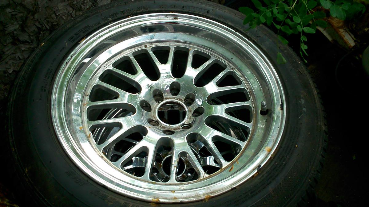
Wheel Show! Post your pics of you wheels
Barrel_Ball replied to k3werra's topic in Brakes, Wheels, Suspension and Chassis
XXR 531 in platinum. 16x8", 0 offset. Wrapped in Falken Azenis PT722 - 225/50R16 On the old car: On the current car, before it was stripped to a shell:
-
L28ET custom exhaust manifold experiment
Barrel_Ball replied to Barrel_Ball's topic in Nissan L6 Forum
Ah, those were the studs for the mounting bracket from the Subaru, who's up-pipe I butchered for that flange. Ha! -
Those are basically the reasons why: First, not knowing they actually had power windows, never having seen an example, although I had my suspicions with the door panel cut marks, and second, figuring I can't get the parts anymore, unless I fork over a premium for them. These were cheap, easy enough for me to convert, and they work. Not everybody can find the rare, exotic, optional parts for their cars, but anybody can fabricate something.
-
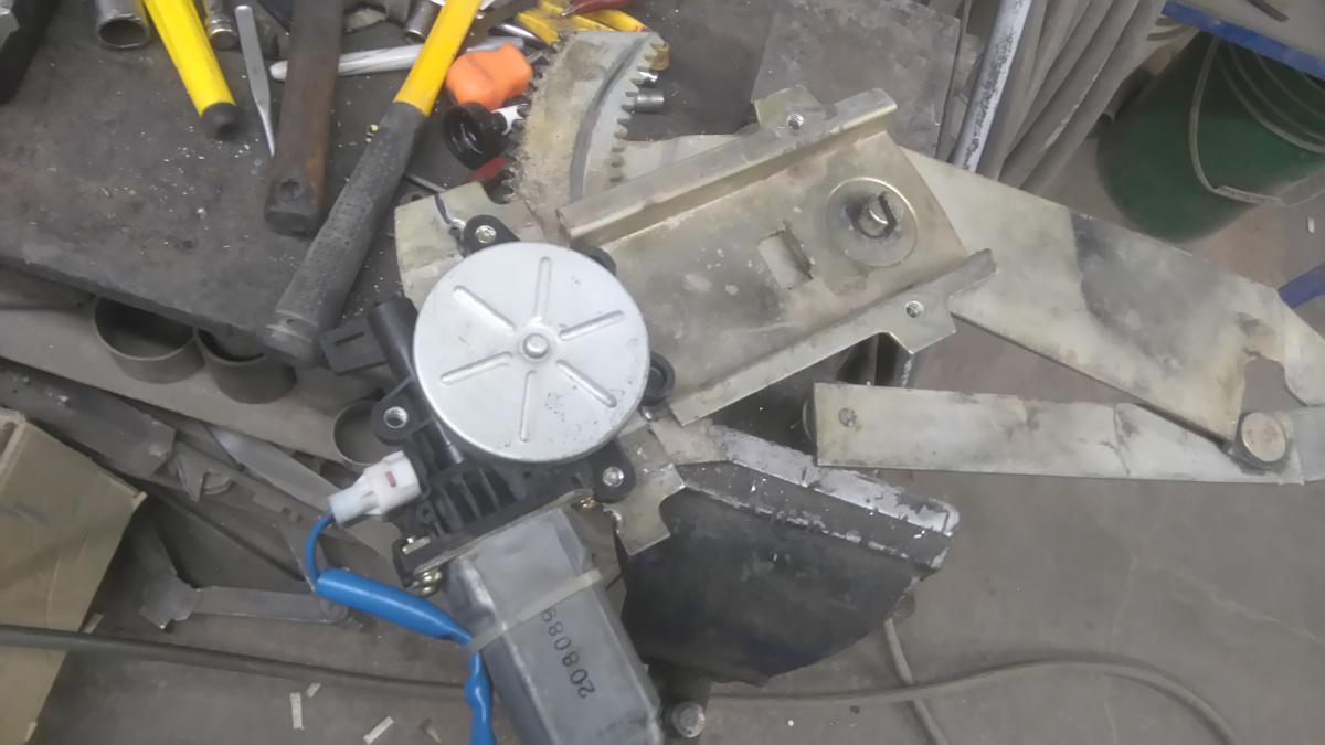
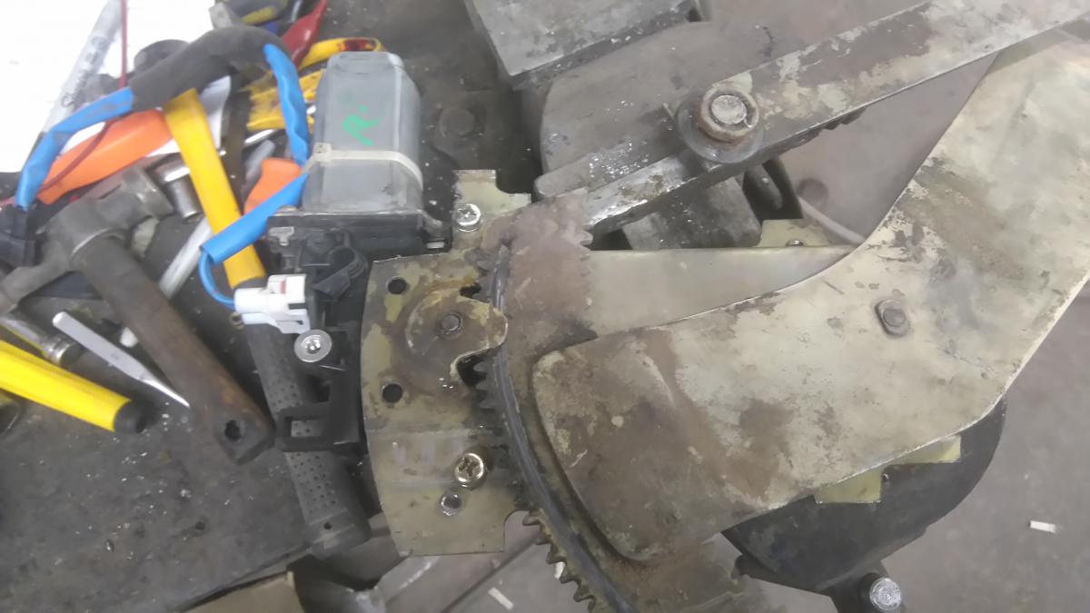
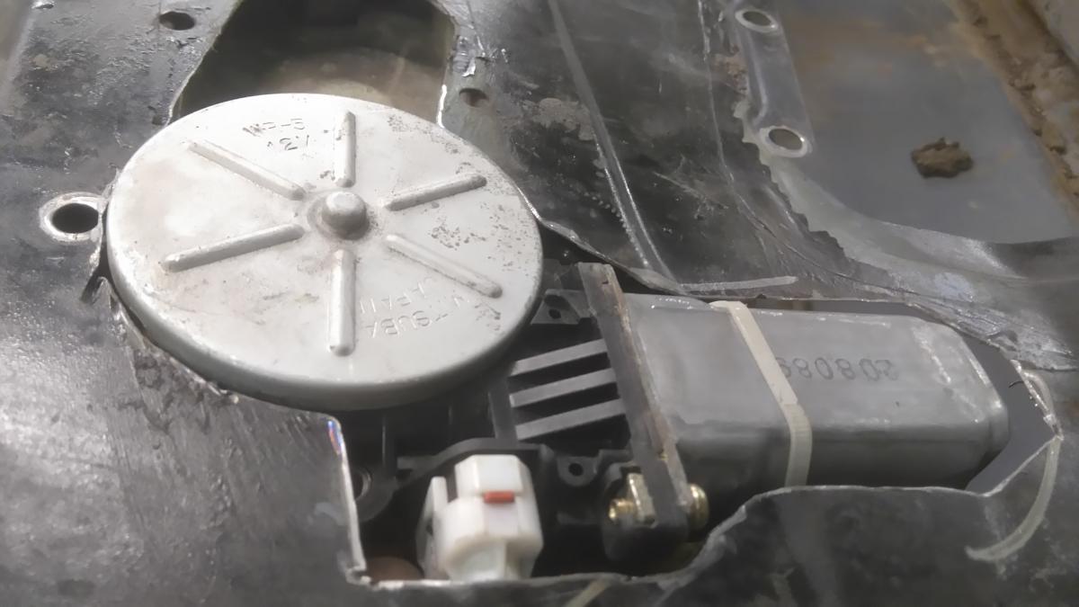
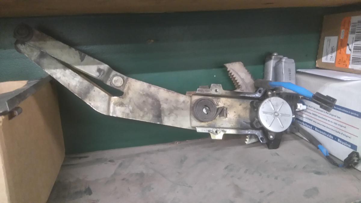
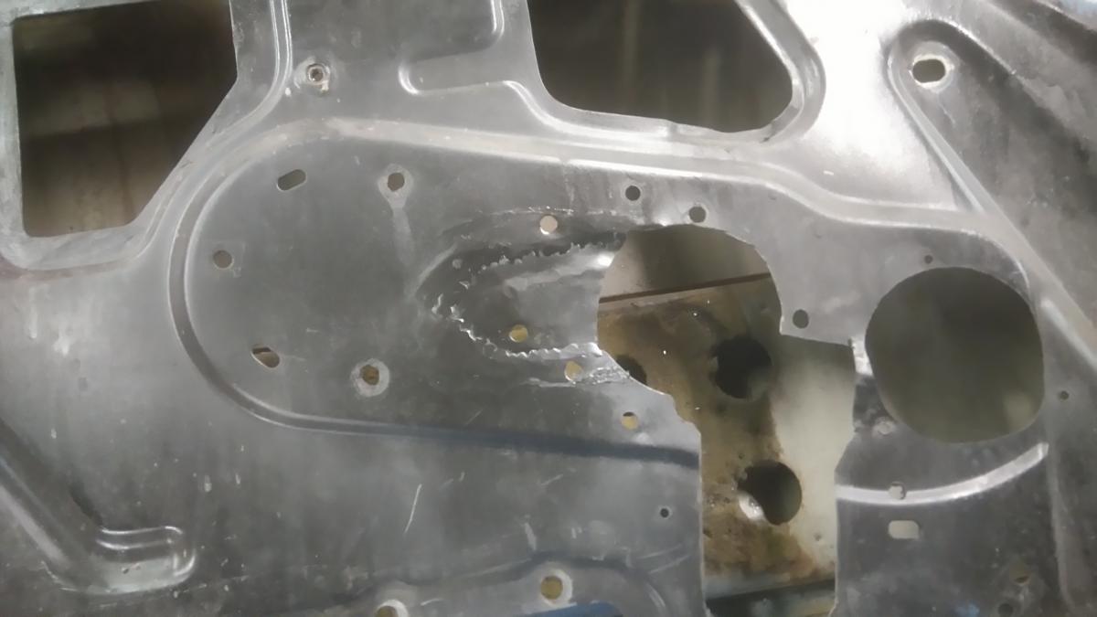
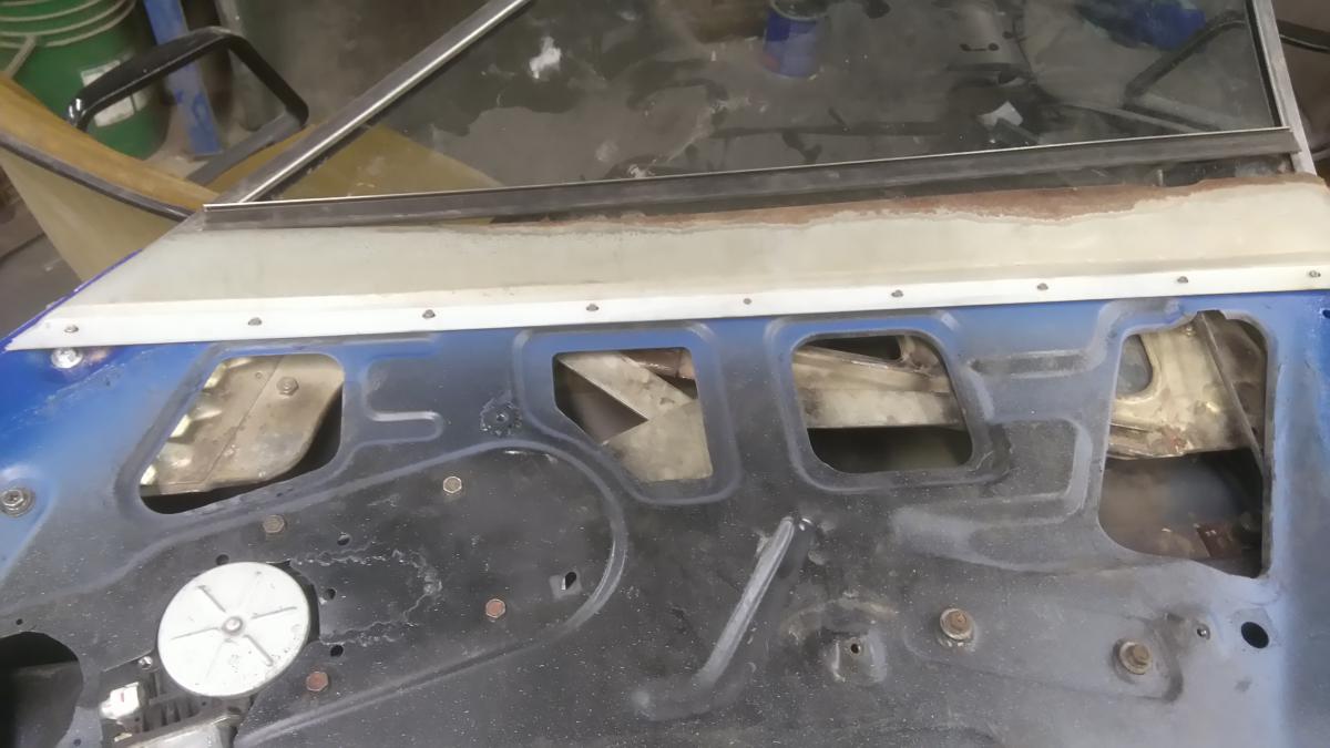
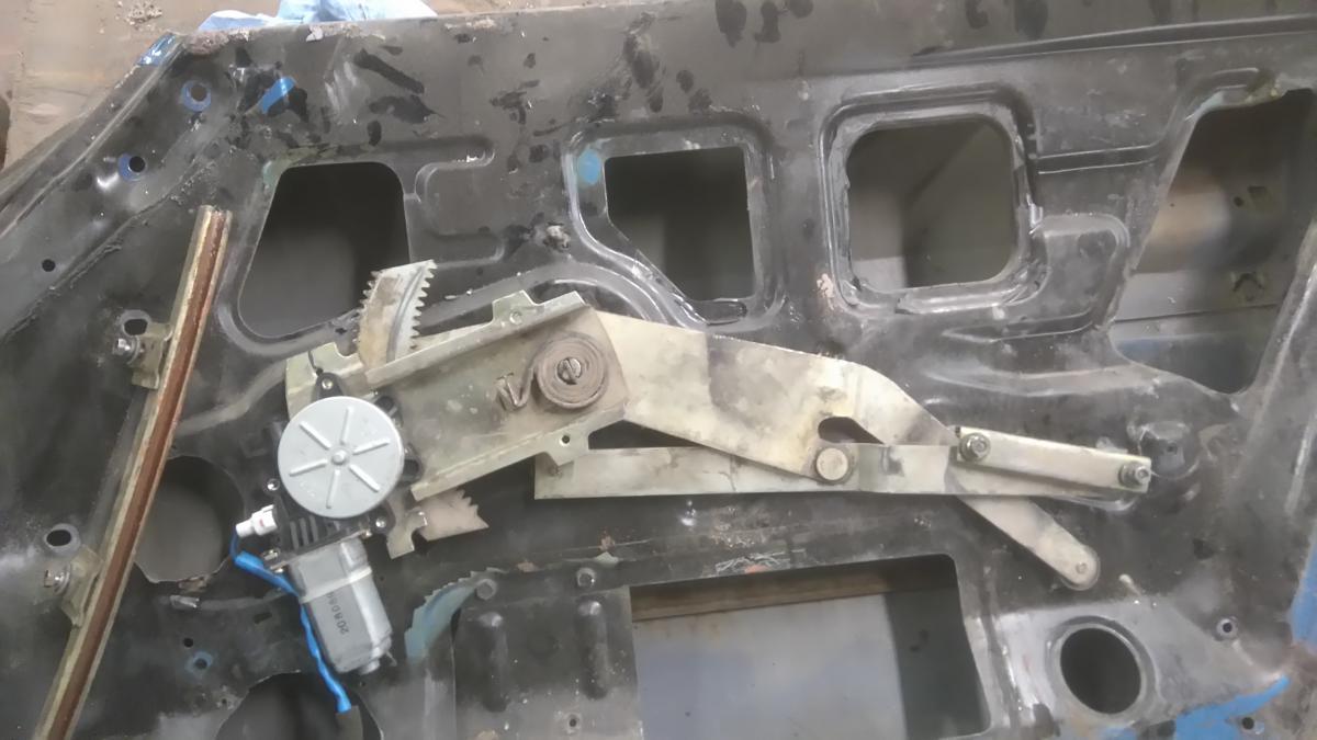
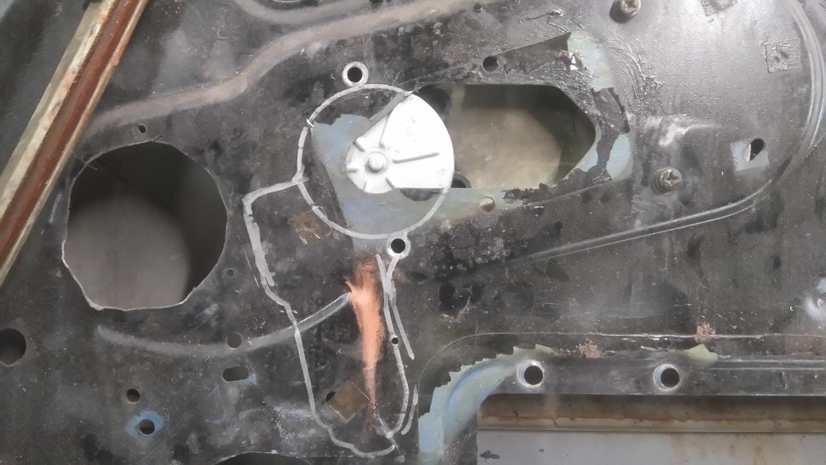
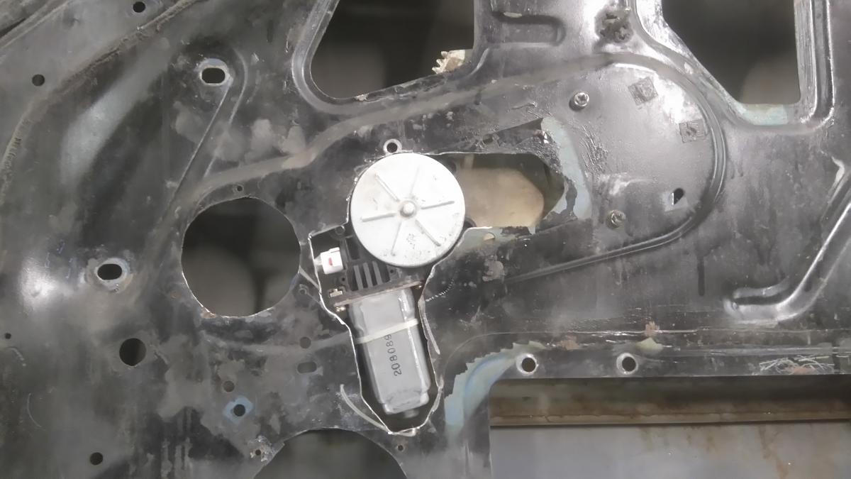
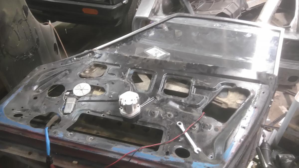
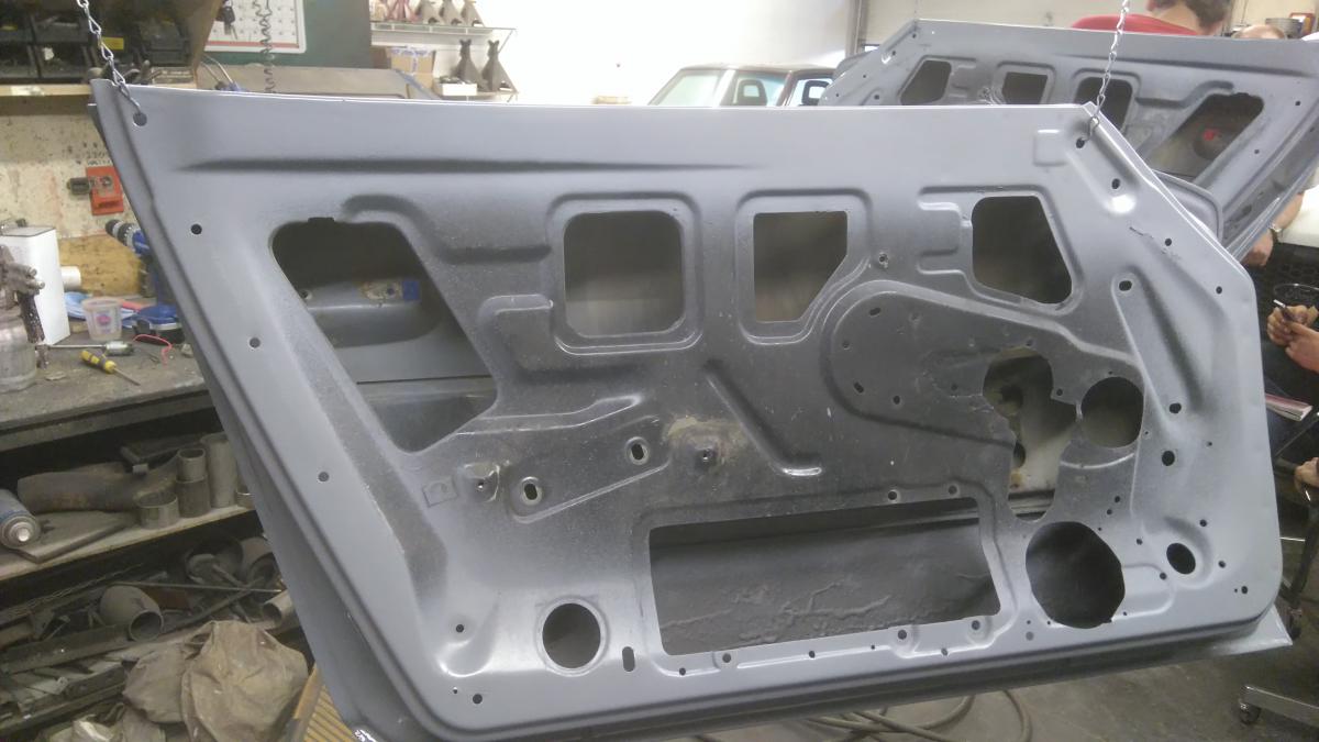
Figured I would post this here, as it pertains exclusively to the first generation Z car. I've seen power window kits that involve a remotely mounted motor, a cable/chain drive of sorts, to a little splined tube that slips over the stock window crank spindle. Problem is, while it may be good enough for many, I find that the fact that there's a protruding black, plastic cap on the door panel where the crank once was, is kind of cheap-looking in my opinion. So I decided, while my doors were apart for bodywork and other repairs/upgrades, to try a power window conversion of my own. Keep in mind, though, that the doors are currently (as of typing this) not on the car, and the switches are not wired into the car, yet (we're re-wiring the car at this time, in fact). So let's go through this with the pictures I remembered to take during the conversion: The motors from the front doors of an '05 Subaru Impreza. The gear tooth pitch is the same as the original spindles, with the two minor details to keep in mind being: The Datsun spindle has 7 teeth, while the Subaru motor has 8 teeth, and the pilot hole needs to be drilled out a little. I don't remember what drill size, exactly. Just make sure it's snug, but still moves smoothly I started by drilling out the three riveted points holding the original spindle in place, removing it. I then determined where the motor had to sit, marked off the area it needed to go, and cut into the bracket mounting flange, so that i could flatten it out around the spindle area. You can see the two holes I had to drill out for the motor to mount. Note the screws. I layed out where everything needed to go on the door to check for any interference points. All clear, so far. Demonstration video of preliminary test here. I bolted the un-finished assembly in place to trace where I would have to cut metal out of the door, as the motor will have to sit through about 1/8" - 1/4". One session with the zip-wheel later... Just pokes through... Assembled everything on the door for clearance/bind testing. All good. Assembled operation test video here. Still needed to final-adjust rails, hence why it wasn't put up all the way. The finished brackets with motors mounted.. I had to trim some of the motor flange back on the regulator, and weld in some trimmed 1/2" x 1/2" angle steel channel on either side to brace the regulator, as well as provide a new mounting flange for the door, complete with new captive nuts. Hard to see here, but I welded in a section of sheet metal to fill in part of the void where the original regulator came through, to add structure back into the doors. Doors are now assembled, adjusted, and sitting in a shed until they're needed for the car's final assembly Not pictured are a pair of rear door window switches from a mid-90's Honda Accord. They are 5-wire, which can handle the current these motors will push. Plans are to use a 20A stud-type circuit breaker per door, may use 2 if deemed necessary. The switches will be mounted in the change pocket of the center console. Not my best install writeup, but I hope this helps anyone who would want to do this type of conversion in the future.
-
1978 280Z (project name: Mothra)
Barrel_Ball replied to Barrel_Ball's topic in S30 Series - 240z, 260z, 280z
I could do that, but I wonder if anybody else has done it, already. I got pictures and a video, but I don't even have the doors back on the car, let alone wired in, yet! -
L28ET custom exhaust manifold experiment
Barrel_Ball replied to Barrel_Ball's topic in Nissan L6 Forum
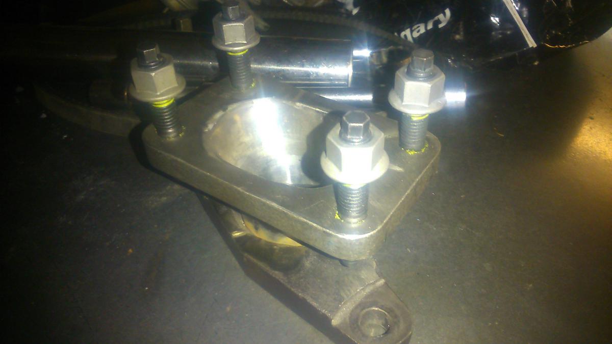
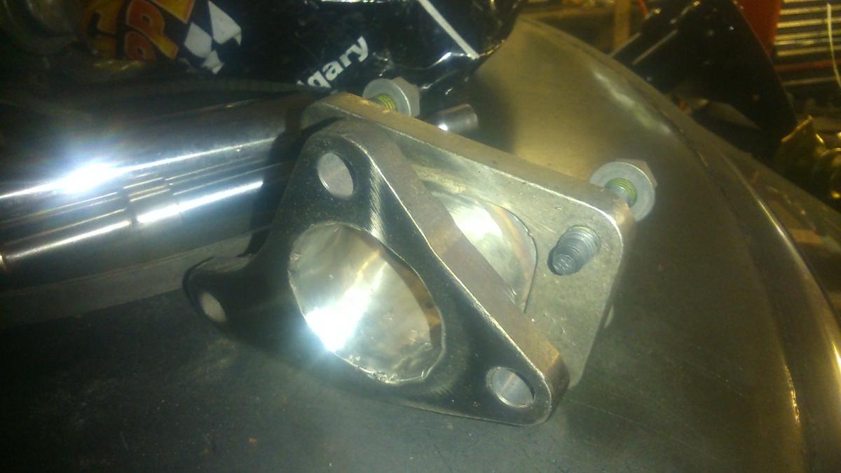
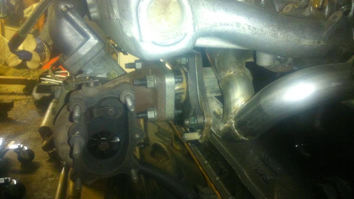
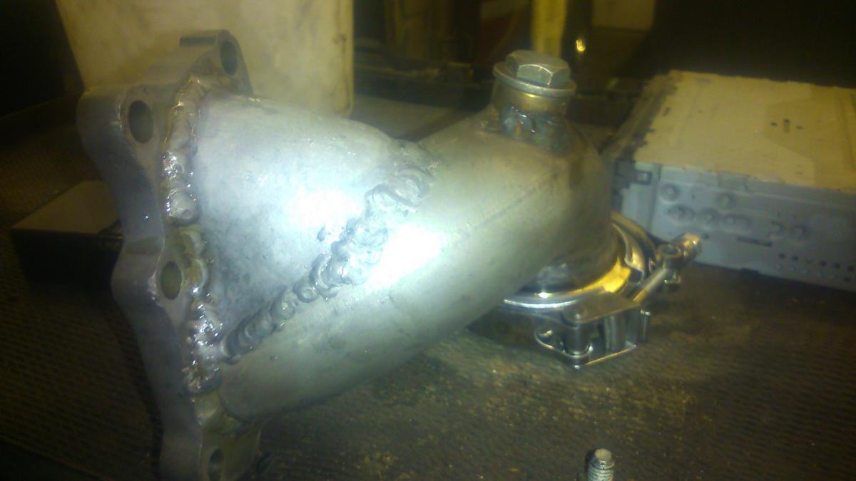
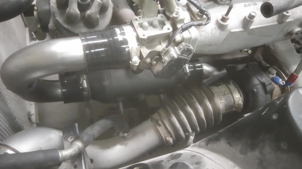
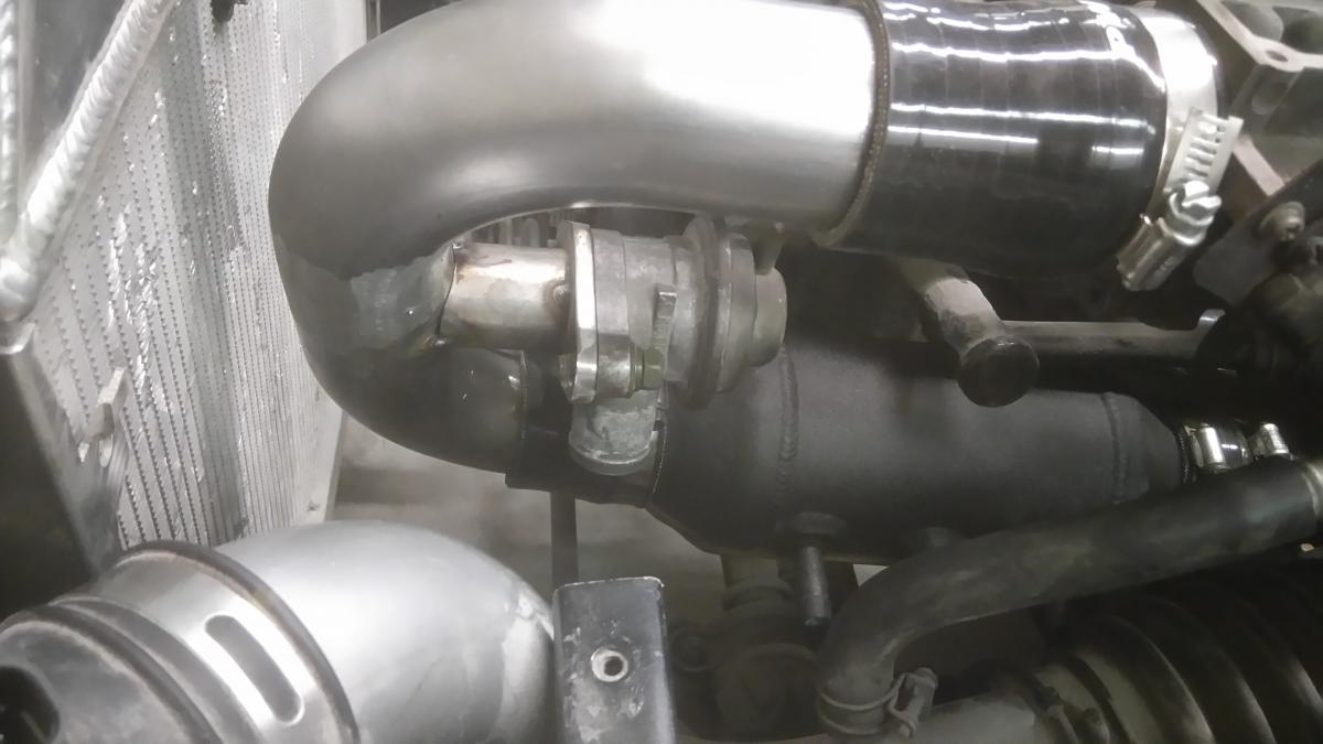
I originally made this with a Subaru turbo flange, since I had an IHI VF52 That I was gonna use, but I had come across a Nissan T3 from an RB25, after it was completed, so I made an adapter to go in between. It spaced the turbo out about 2 inches, but that turned out good in the end to make room for my intercooler setup.
-
L28ET custom exhaust manifold experiment
Barrel_Ball replied to Barrel_Ball's topic in Nissan L6 Forum
Dumb question: Before, or after where the others collect into them? There's plenty of room after the 3-1 joints, but before them, I'm not so sure, yet. I'll see what my local performance shops have, and measure from there. -
L28ET custom exhaust manifold experiment
Barrel_Ball replied to Barrel_Ball's topic in Nissan L6 Forum
Not sure I'd trust slip-joints to not leak on a turbo manifold. I am thinking, though about adding a support bracket, from the turbo compressor housing, to the intake manifold. I have read that supporting the turbo with just the header isn't a good idea, since as the header heat-cycles, the weight of the turbo could cause the whole thing to sag. I'm not too worried about it, right now, as I still have much work to do, before the car runs again, what with no front wiring harness, and all. You can make anything work - Where there's a will, there's a way. -
1978 280Z (project name: Mothra)
Barrel_Ball replied to Barrel_Ball's topic in S30 Series - 240z, 260z, 280z
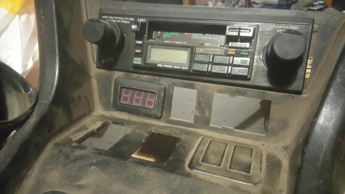
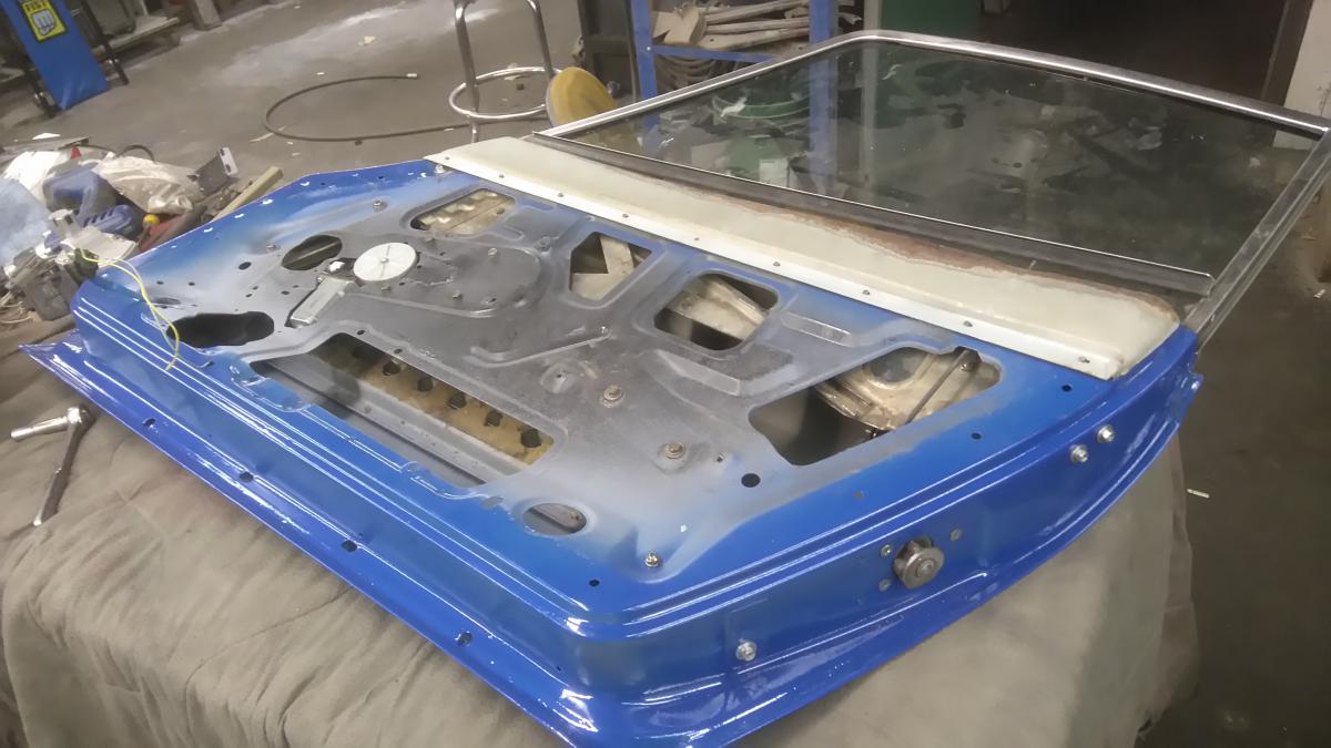
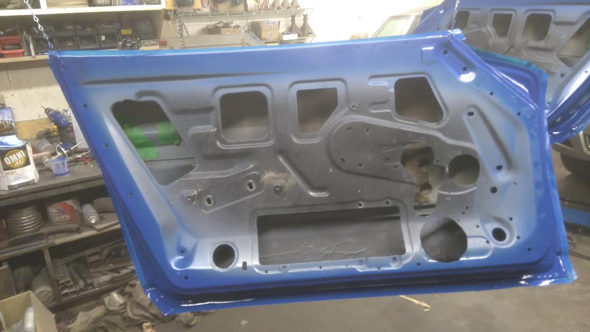
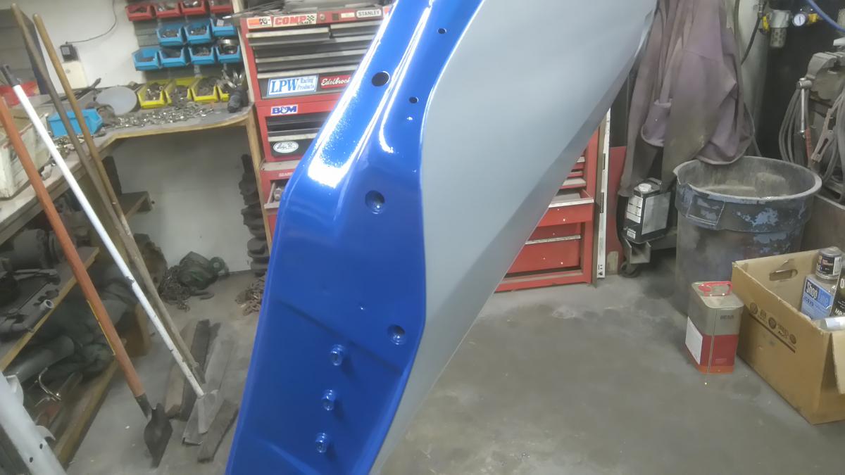
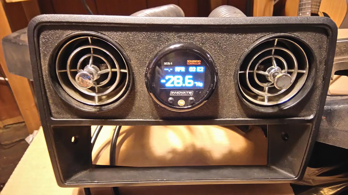
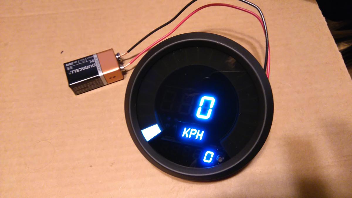
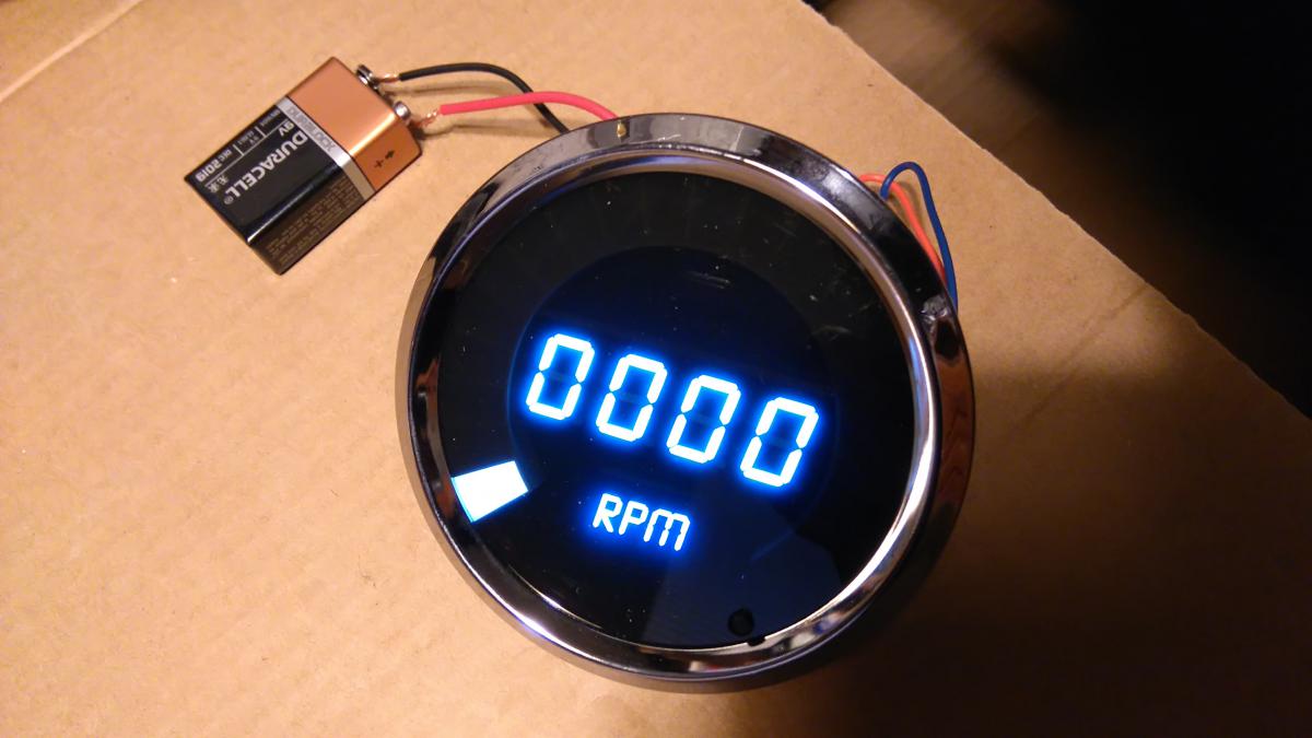
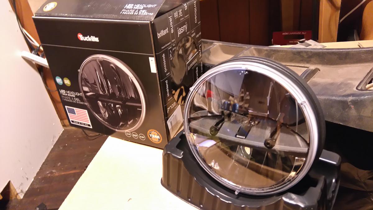
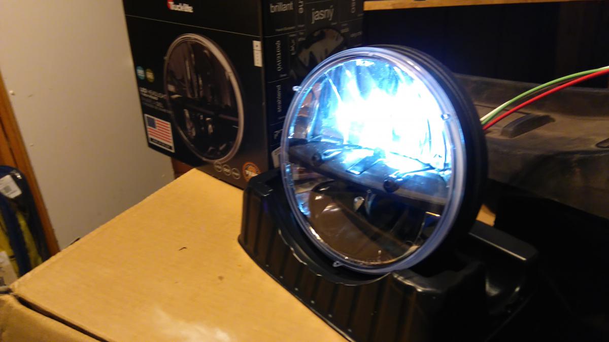
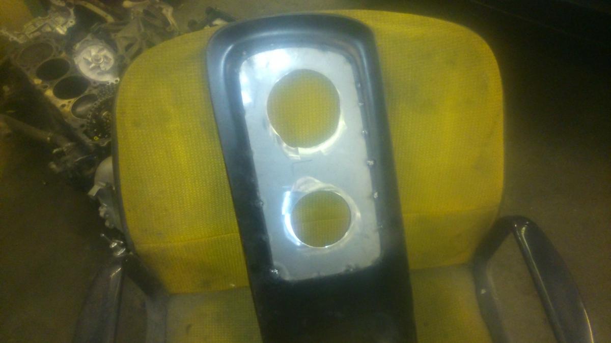
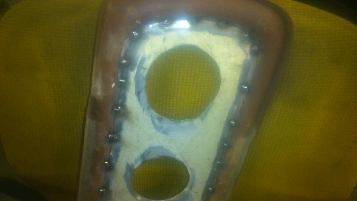
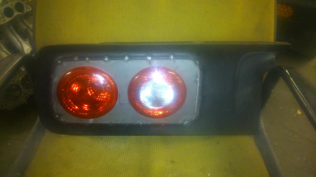
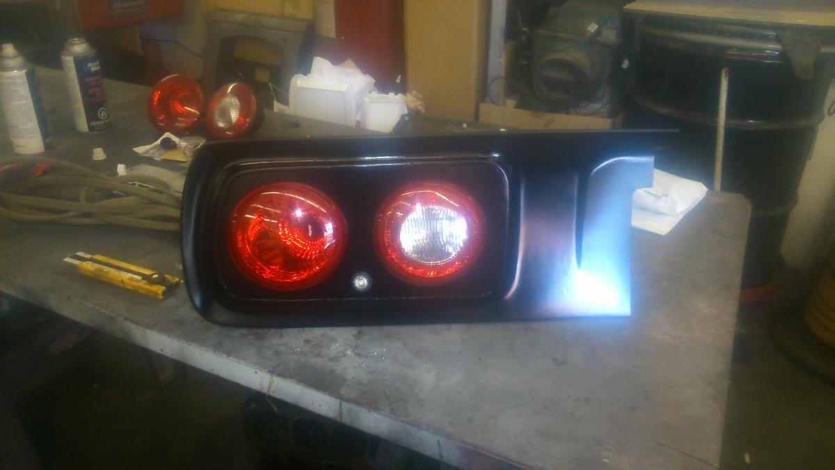
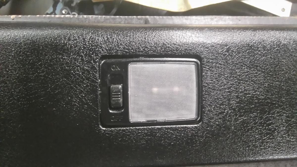
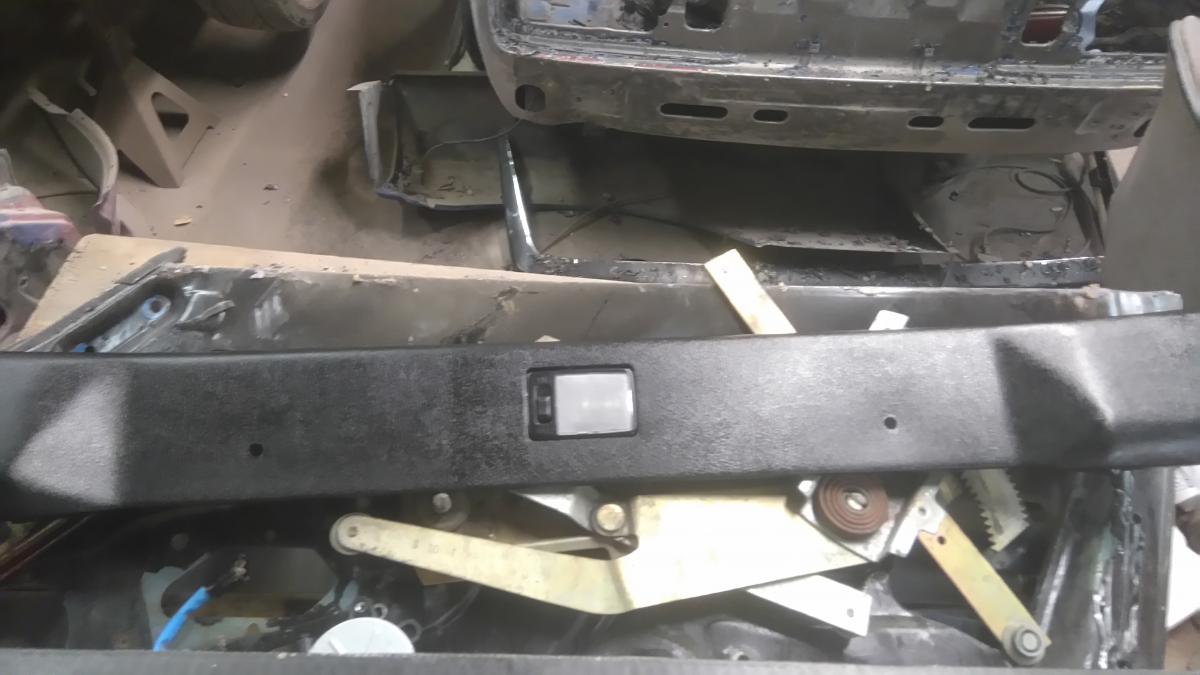
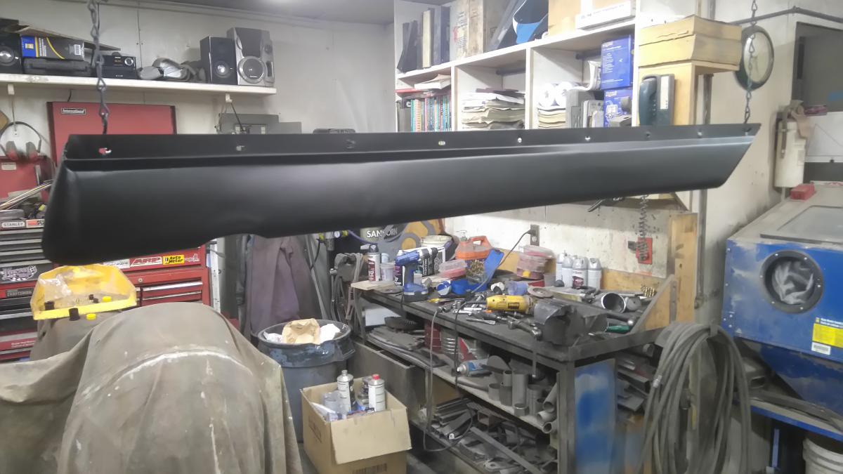
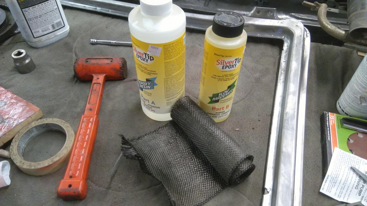
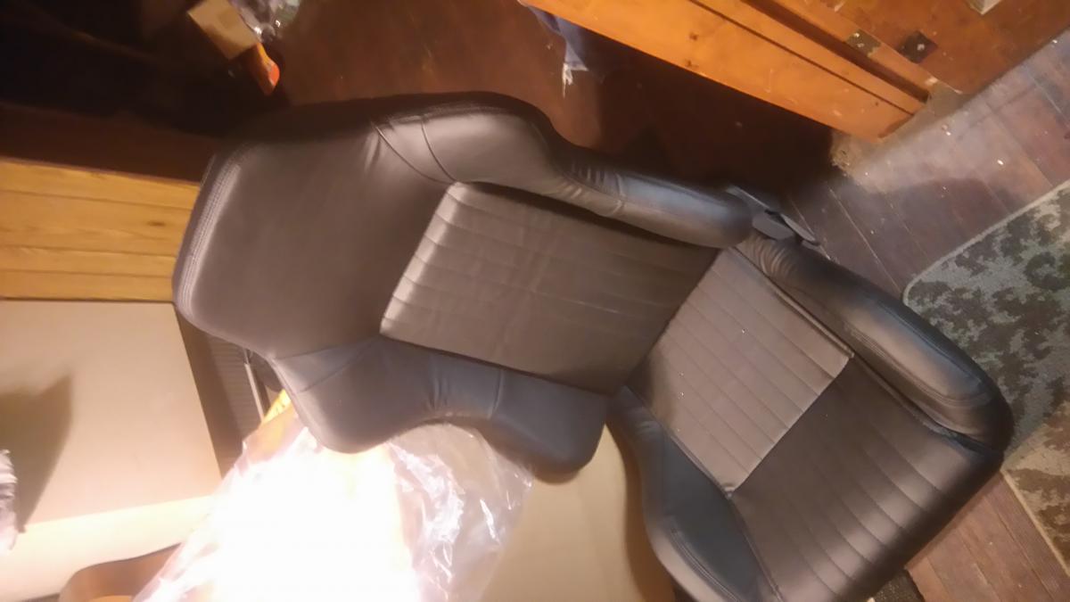
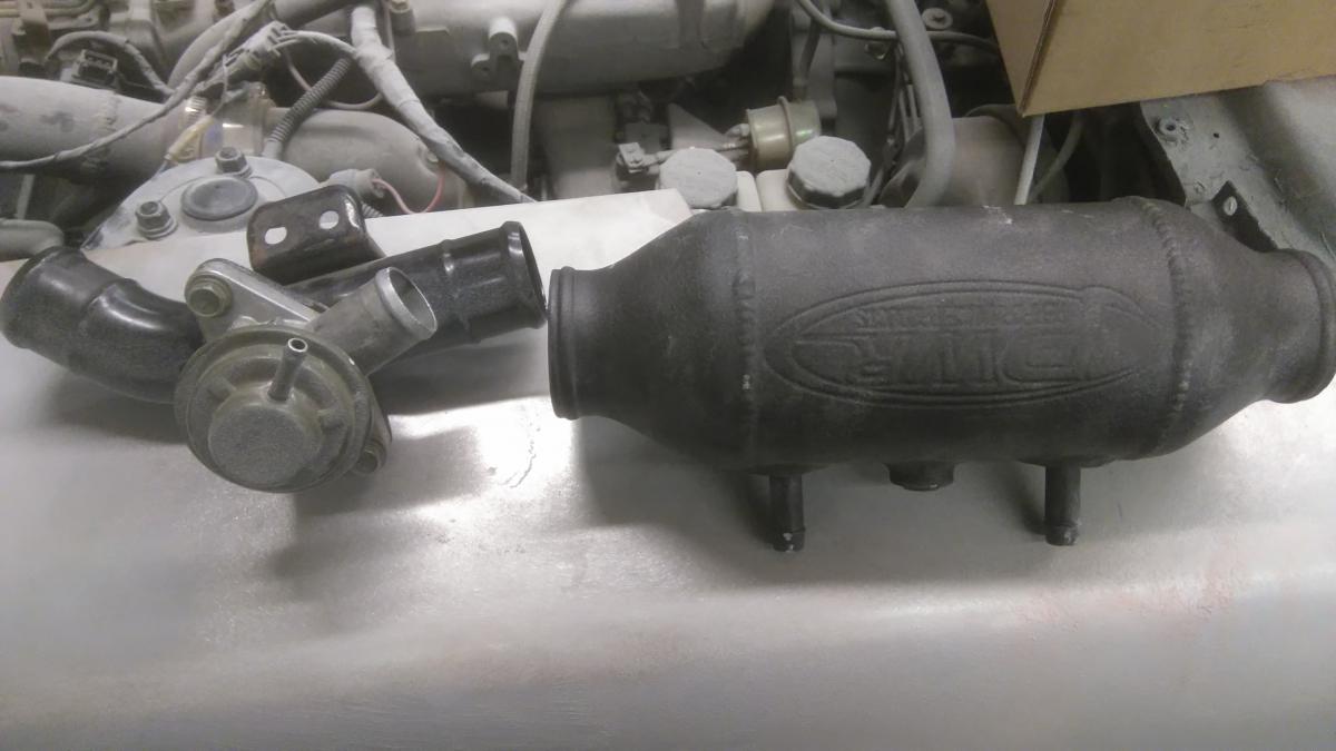
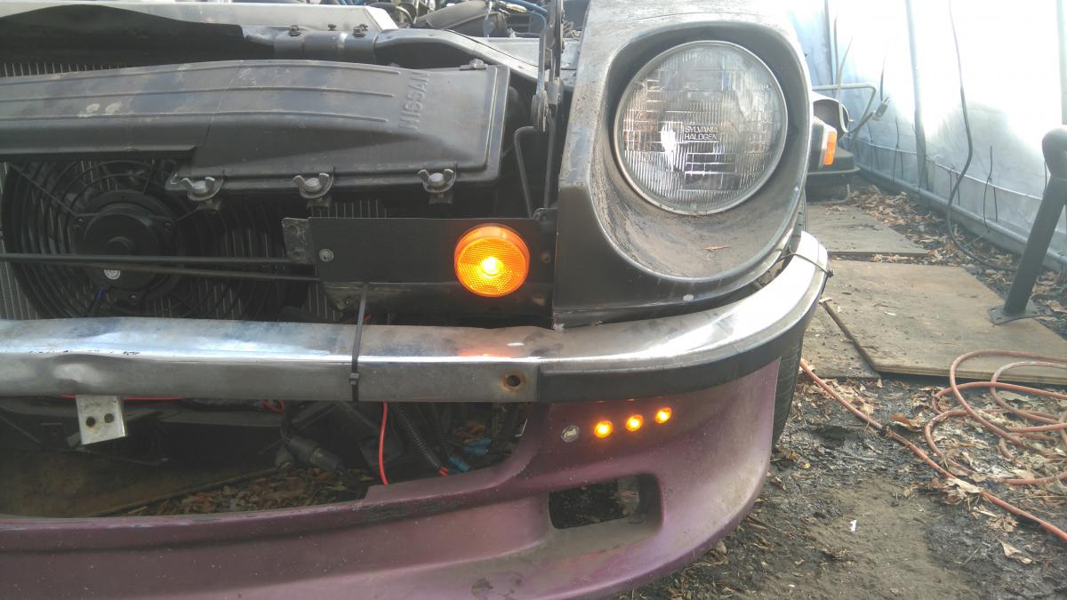
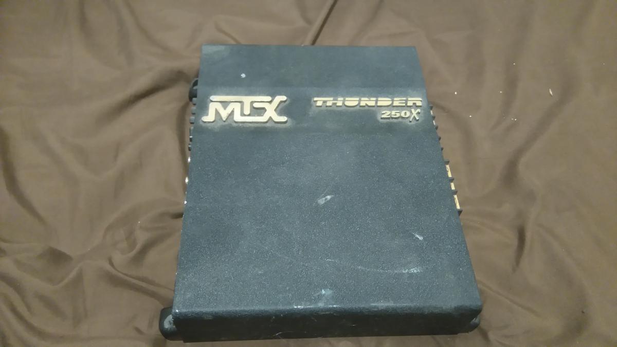
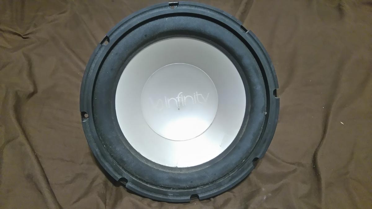
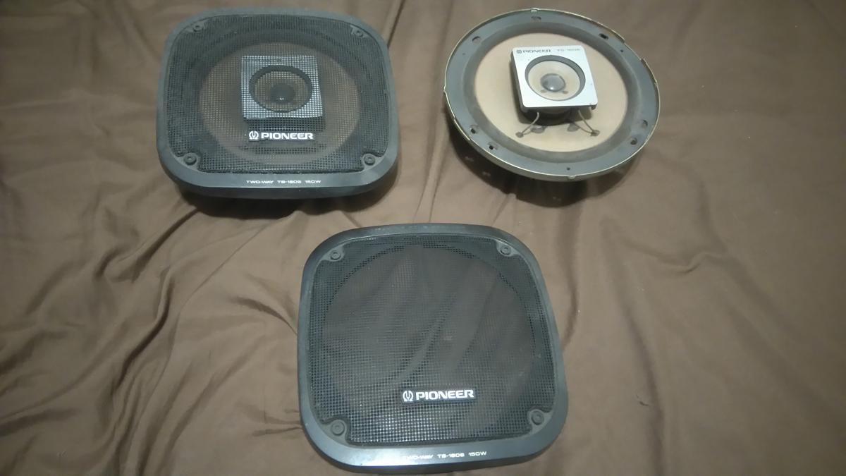
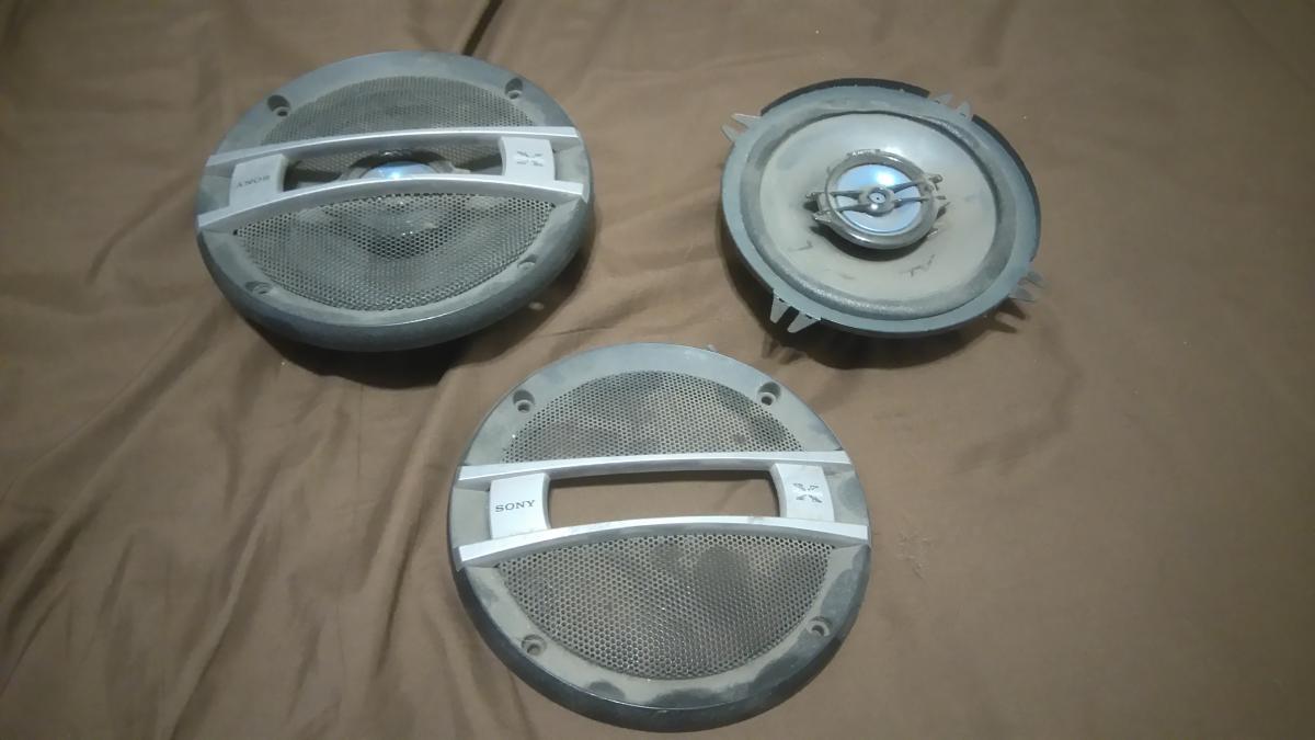
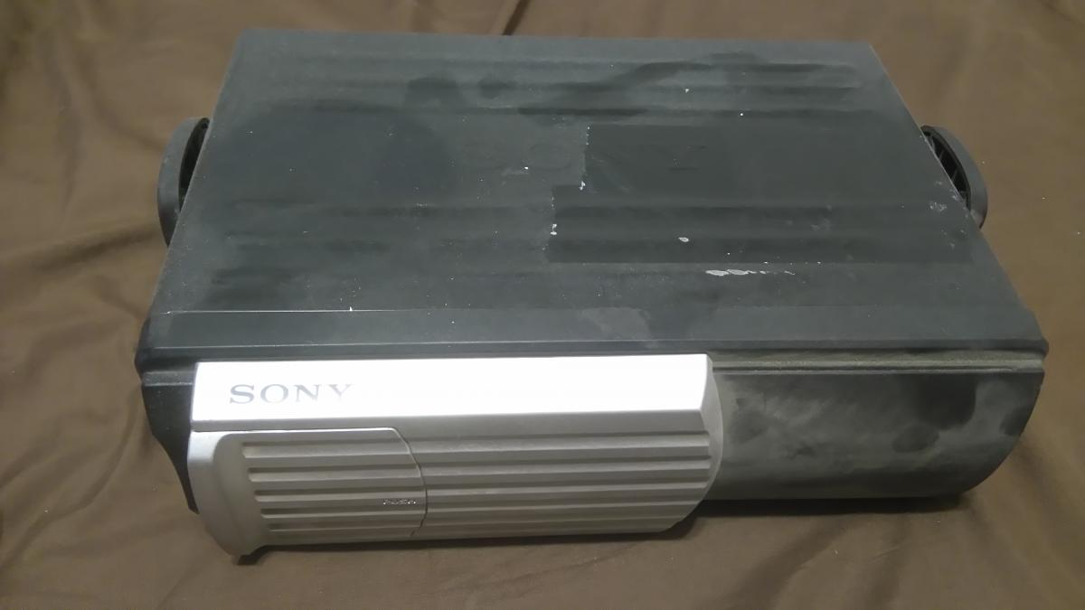
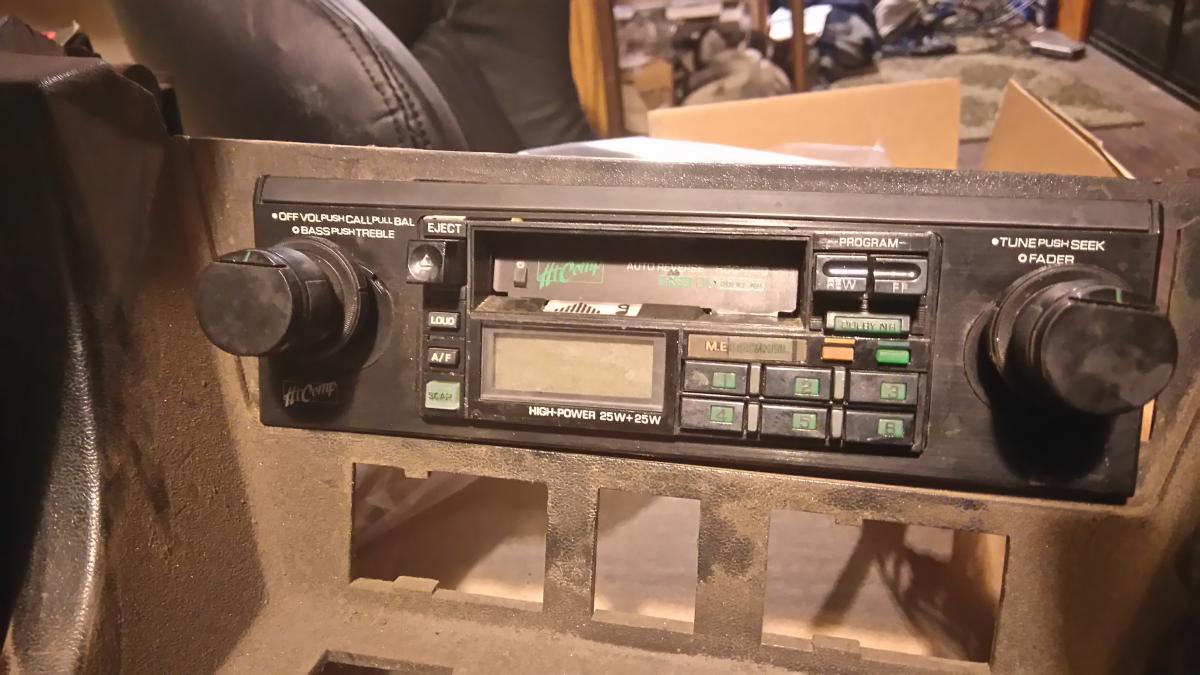
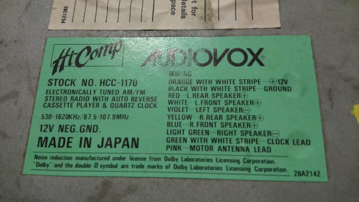
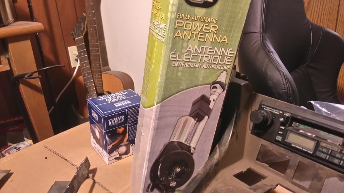
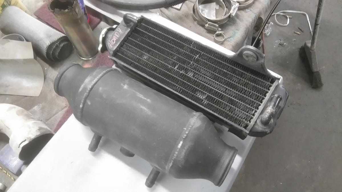
Doing a part 2 of this opening, because I didin't know the limits to how big each post can be, so here we go: I decided to partake in a bit of mechanical voodoo with the doors: Motors are out of an '05 Subaru Impreza. Gear tooth pitch is the same, but the tooth count is up by 1. Still works. Making this stuff work. Tracing where the motor needs to peek past the door sheet metal After the cut Close-up Testing The finished part, with bracing and new front bolt locations. *Will be using a pair of back door power window switches from a mid-90's Honda Accord While we're on the subject of the doors, they're the first parts to see paint/primer. Currently going to leave the car in epoxy primer, and simply paint the door jambs, hatch area, hood seam, and window lips. We just don't have a dust-free facility to paint it, right now. The Jambing will make blending in much easier down the road. The color in question is Volkswagen's 'Jazz Blue Mica'. Think MK4 Golf R32 color. Currently, the dash is out, and we're re-wiring the front half of the car, using a Painless 12 circuit fuse block, a couple hi-amp breakers, and a GM 100 amp alternator. The gauges are also all being replaced with digital, and stepper-motor, LED-lit instrumentation: Innovate SCG-1. Boost controller, wideband AFR controller, shift light, all in one, convenient 2" guage. Complemented by a revised center vent bezel. Intellitronix LED digital Speedometer and Tachometer in white lighting. The LED sweep is kinda neat. These will be accompanied by a trio of the Autometer GT series stepper-motor guages: Coolant temp (comes with sender), Oil pressure (comes with sender), and Fuel level (programmable). Continuing with the LED trend, outside, are these bad boys: Trucklite LED headlights. 1.8 amp draw on the low-beam, 3.6 amp for the hi-beam. For tail lights, some 240Z tail light panels have been modified to take a set of Chevrolet HHR tail lights: Not a bad concept, so far. When finished. Outers are now just brake/tail, inners are now signals, all LED. in between them is a 5/8" white penny light as a reverse light. All DOT street legal. On the car. Will finish conversion, later, as we still need to figure out mounting, and cabin sealing at this points. On the front, we have a medley of lighting, with the turn signals now being a 2" reflective lens puck-light, and the lower markers being 5/8" amber and white penny-lights. Moving back inside, the dome light has been changed out with one from a Toyota Prius, so you could say I have hybrid parts in my car! Looks pretty sleek in there. Seemless... When I got the car, the door panels were pretty much destroyed, so I had an idea... "What's that...?" Harder than it looks. But the end result is worth the effort. Here's one of the seats. $400 for the pair. Firm, but better than sitting on milk crates. For an audio System, the plans are an MTX Thunder 250X amp An Infinity Reference series 10" sub in an enclosure behind the seats A pair of 90's Pioneer TS-1606 6" speakers on either side of the sub A pair of 5 1/4" Sony Xplod's in the doors (only temporary) A sony 10-disc CD changer in the rear hatch area All fed into by an Audiovox digital Tape deck. I figured "The center console I have is perfect - It even has the original twin-pin radio stamp-out!", so I decided to use a decent tape deck, circa 1980's. I'm even using a power mast antenna. And my latest episode of madness: PWR air/water 5x6" intercooler core with accompanying pump, Honda CR80 radiator as a heat exchanger, and an R33 skyline GTS-t recirc valve - identical to the DSM 1G valve.
-
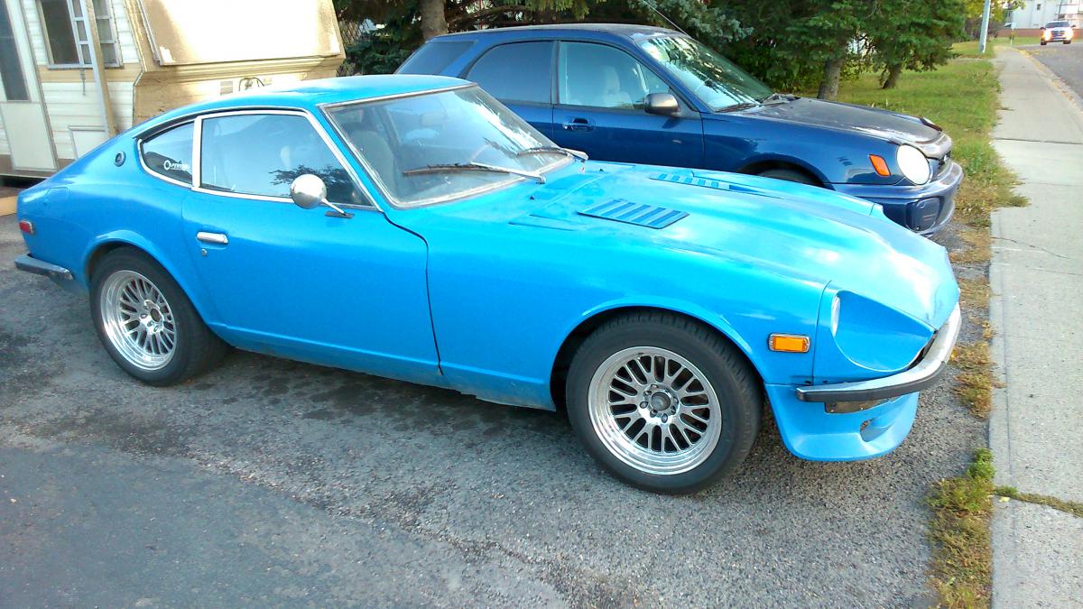
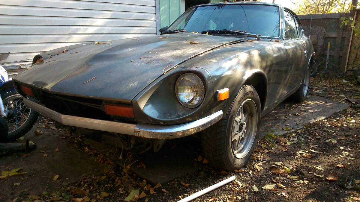
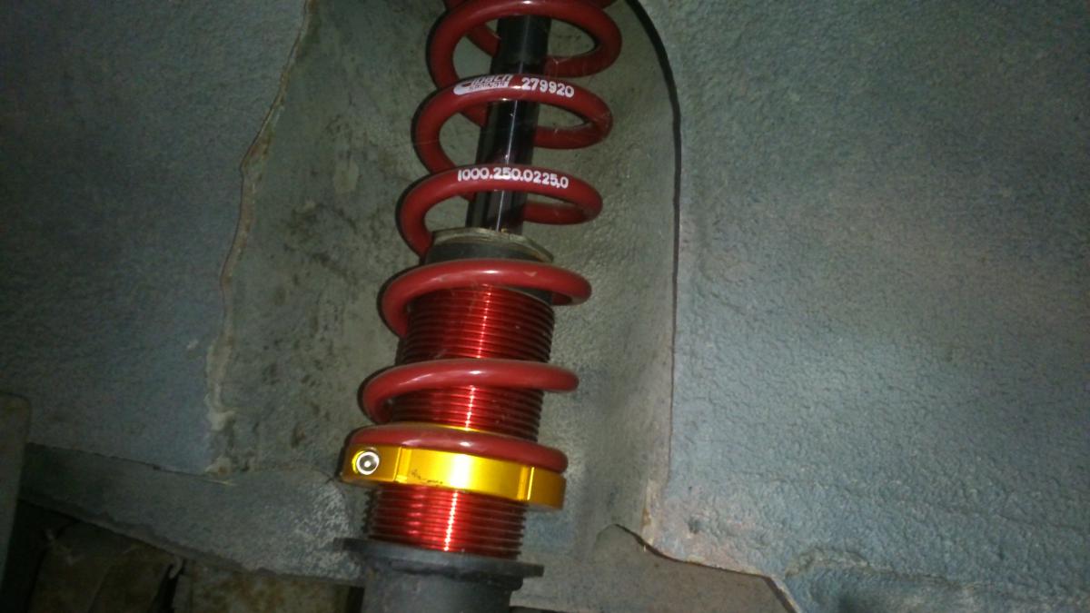
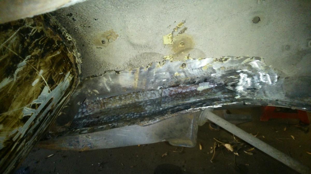
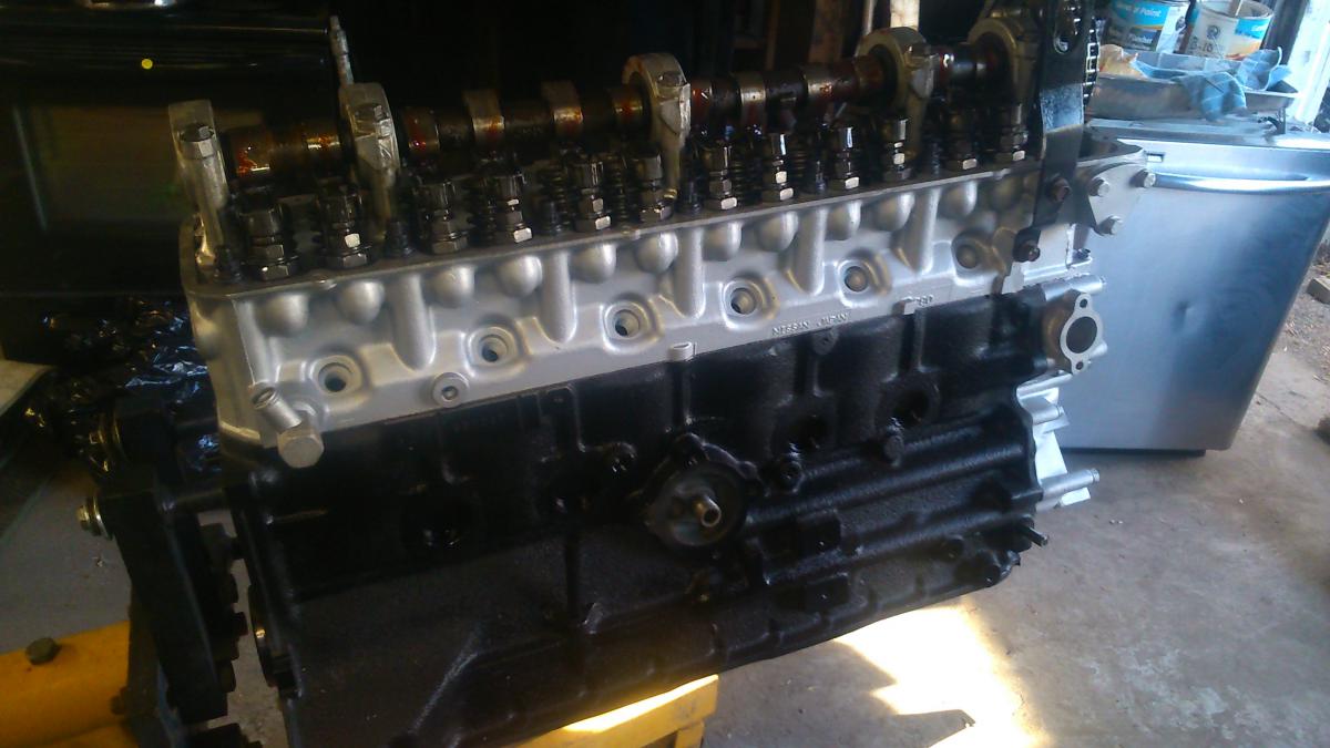
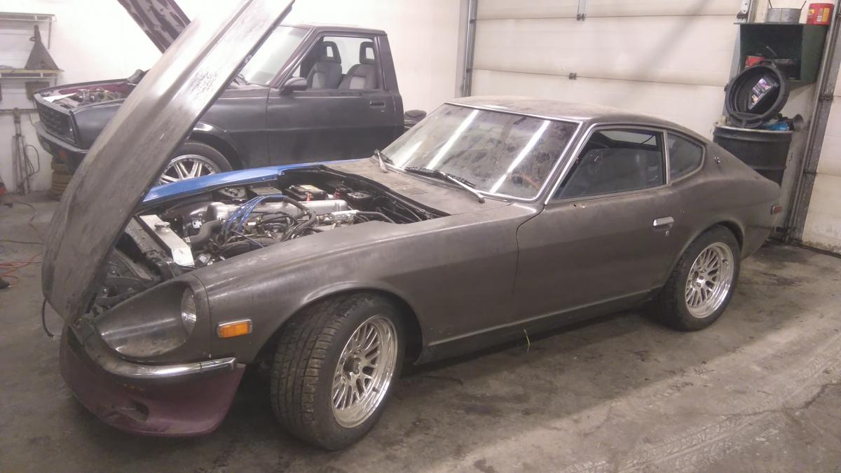
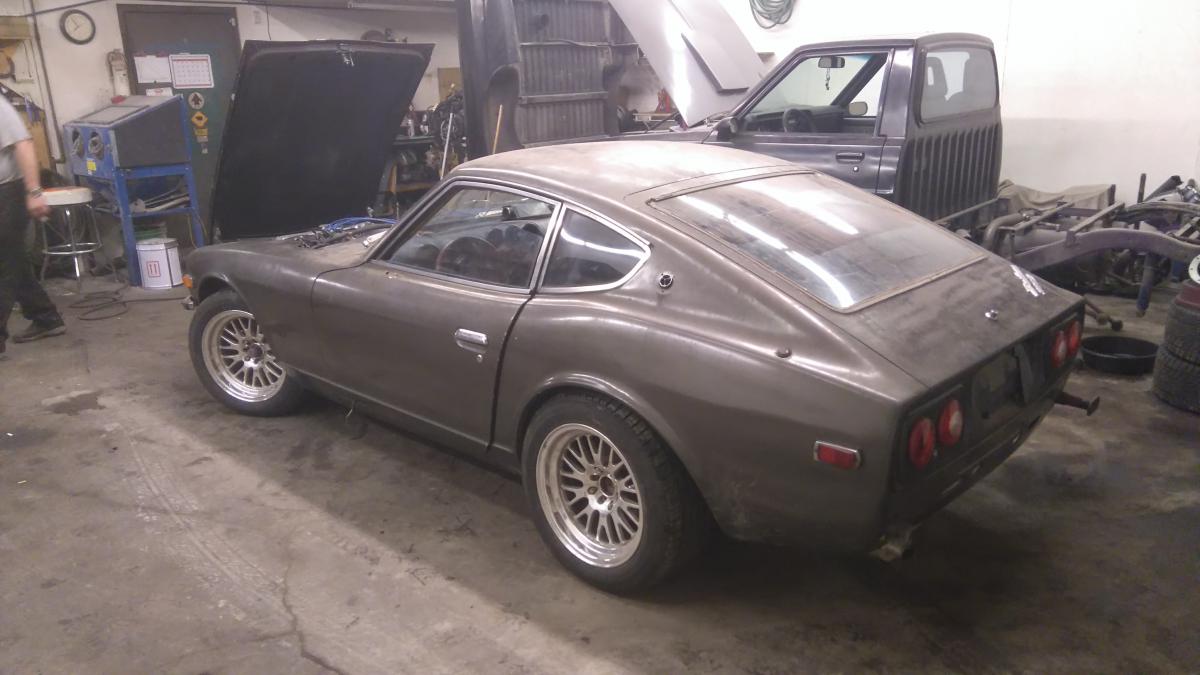
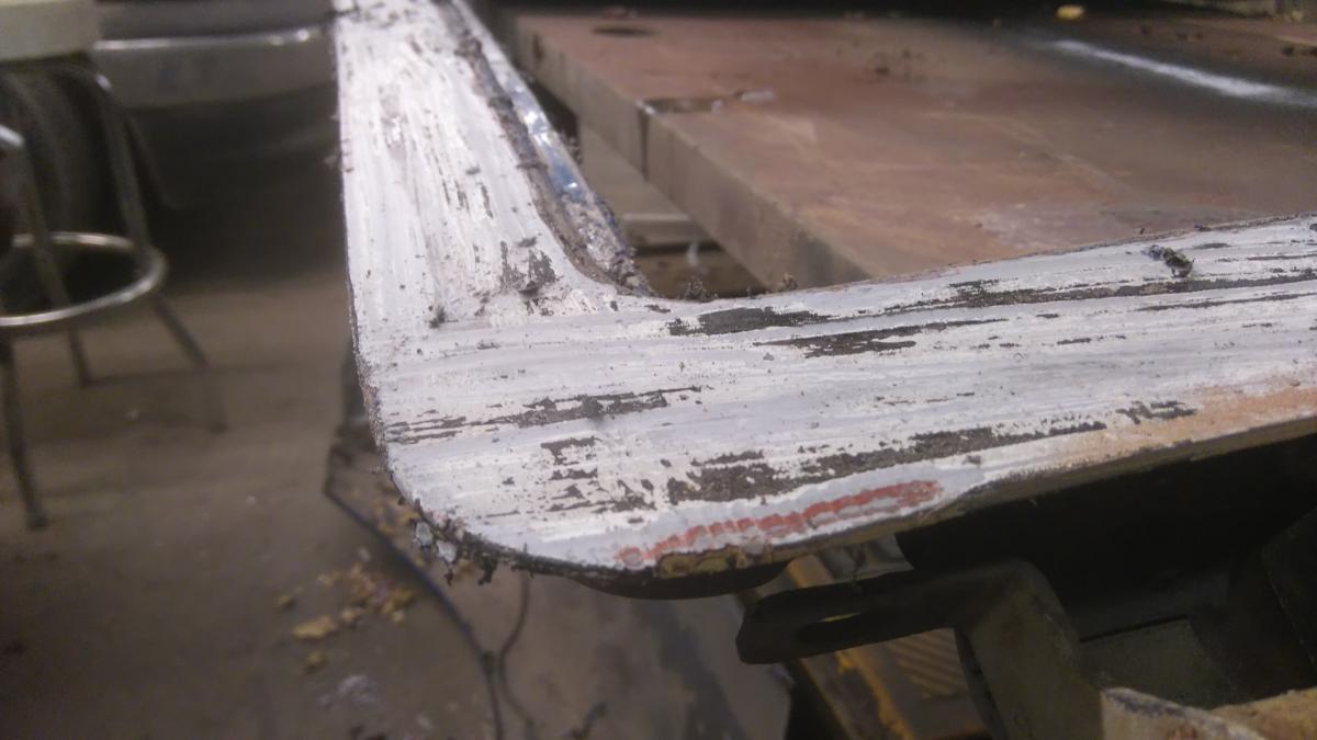
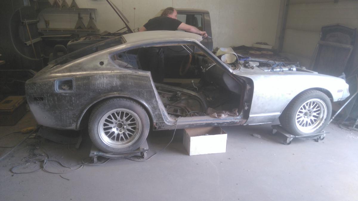
First Z died from a combination of chassis rot, failed engine and brake components, and abrupt contact with a Chev Optra 5 rear bumper, so I decided to instead, build the second car I bought that same year, with parts from the old one. Bought in 2013, from a nice guy in Chestermere, AB. Car came out of Idaho, with no prior registration in Canada, let alone Alberta, so there was lots of work to be done. Car also came with some goodies, like the TechnoToyTuning rear control arms, and DIY coilover kit already installed, as well as the once-coveted RWD 810/Maxima rear brake brackets. Lucky! Good friend, and fellow user, z240, helped me out with chassis and frame repairs, among other improvements to the car, as the driver's floor board did look like swiss cheese. Inside of frame rail - note the rust-proofing coating New plate going in place Upgraded water drain solution to prevent fender rot Then, when I went to swap the engine over from the old car, I noticed some piston skirts were broken, so I had it rebuilt! Full rotatint/reciprocating assembly has been balanced, ITM hyper-eutectic 0.5mm (0.020") oversized pistons, A-grind L28E camshaft ('77-'80, internally oiled), minor head port cleanup, 5-angle valve cut, ARP head studs, main studs, and rod bolts, KA24E oil pump, N42 non-emissions intake, custom equal length exhaust manifold with turbo adapter, and an RB25 series 1 turbo (aluminum/ceramic) with custom bell-mouth dump pipe. Car sat for a small bit, then It went to another friend's house, where it sits now, being worked on: Even has the old car's XXR wheels! Chev HHR tail lights add a neat touch. Grafting a section of fender to get rid of rot. Removing the staggering amounts of paint (up to 10 layers) and body filler (up to 3/8"!). The hatch was binding on the body, there was so much buildup! How the car sits, at the moment. There was alot more good sheet metal than there needed to be body filler plastered over. You can now see body character lines.
-
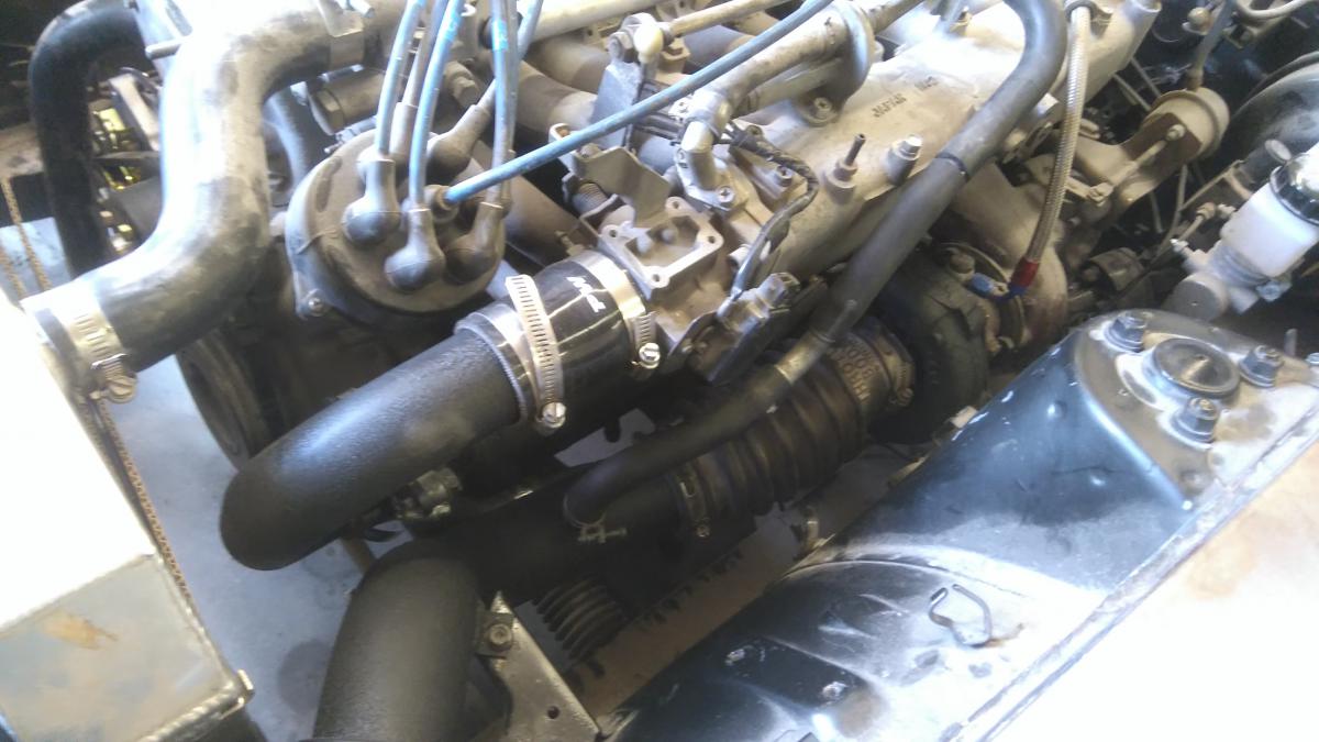
I think somebody mentioned an air/water setup, earlier? PWR 5x6" core, will be using a Honda CR80 radiator as the front heat exchanger, and an RB25 recirc valve. Probably the shortest, intercooled piping setup on one of these engines. We're almost done with the fabrication, just need to plumb the recirc outlet, and paint the pipes before doing the coolant plumbing. EDIT: Done fabrication and paint. Core is installed. Even runs stock air box!
-
I'm sure some starter reduction gears are planetary gears, so they look like a stock non-RD starter. I know mine has the higher-pitched whine, and a lower cranking speed of an RD starter, but looks like a stock one.
-
L28ET custom exhaust manifold experiment
Barrel_Ball replied to Barrel_Ball's topic in Nissan L6 Forum
Never, have I seen expansion joints (you mean those accordian-like sections, right?) on a stainless, tubular, turbo manifold. I can understand, with Mild steel, and occasionally, cast iron, due to different expansion rates with those materials. Could you point out where I would need them, and why? This is purely in the experimental phase, so if it does crack, I can figure out where it cracked, why, and rectify the problem to prevent it happening again. It will have to come out again, anyway for ceramic coating once I've determined it a success. The demo video I posted shows not only the difference in sound, but at-rest turbo response, as well. That may not say much at this time, but I'm being optimistic, here. As for a road test video, that will still be a ways away, since at the time of the test runs, the car wasn't tuned yet, and now it's in pieces, getting re-wiring and bodywork, as well as other improvements and repairs. Might see the car on the road for August, but no promises, there. I will assure you, though, that further updates on the development will appear as they unfold. For the time being, though, let's discuss. -
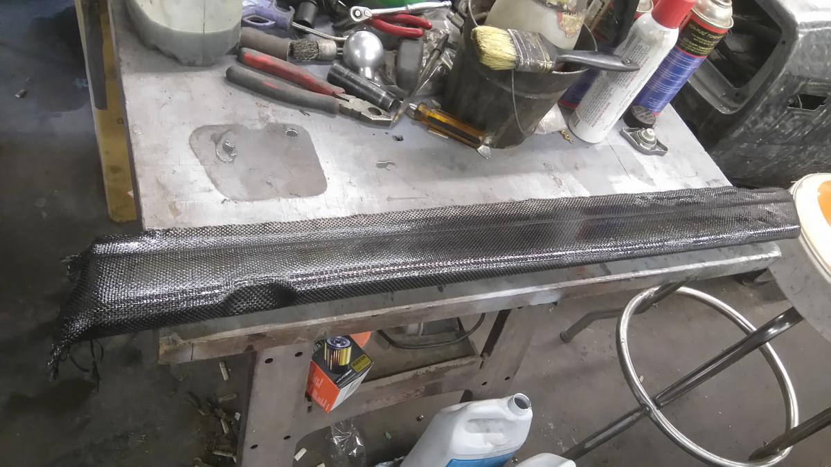
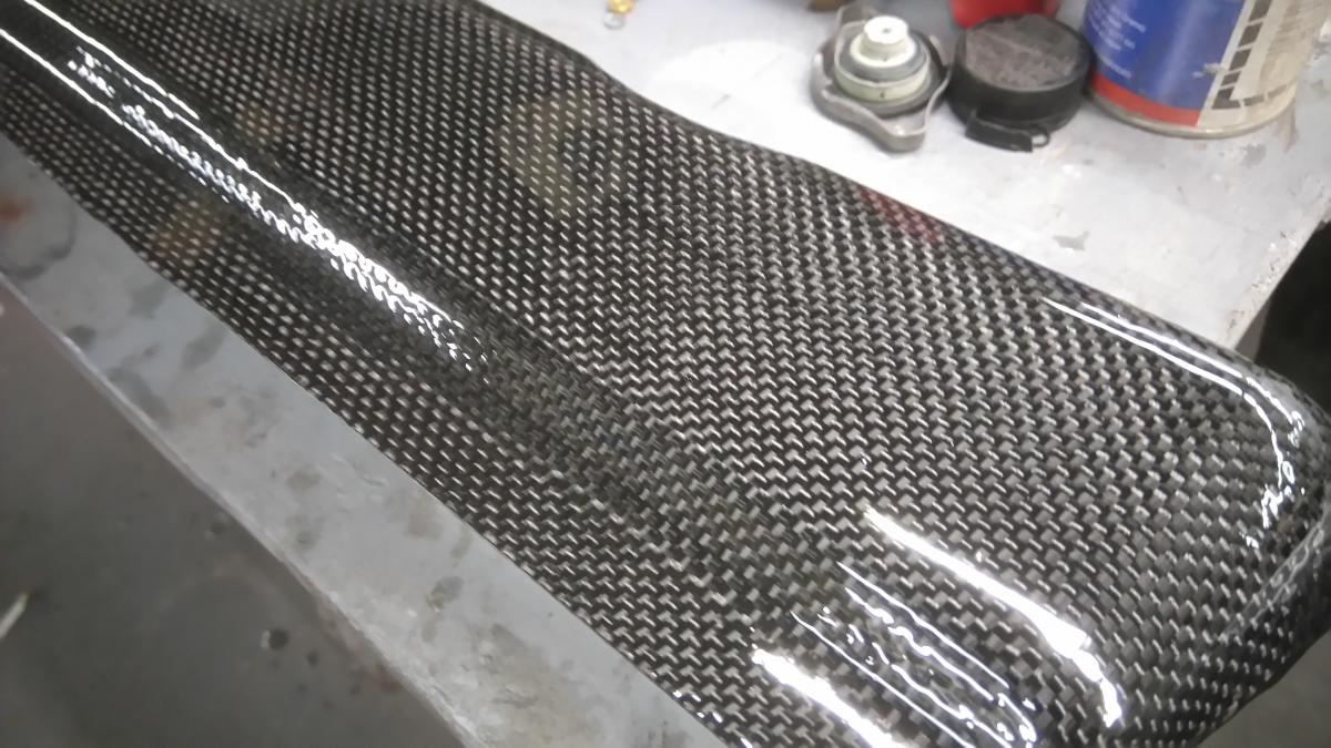
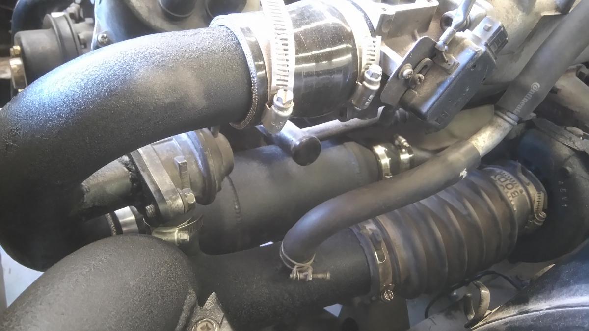
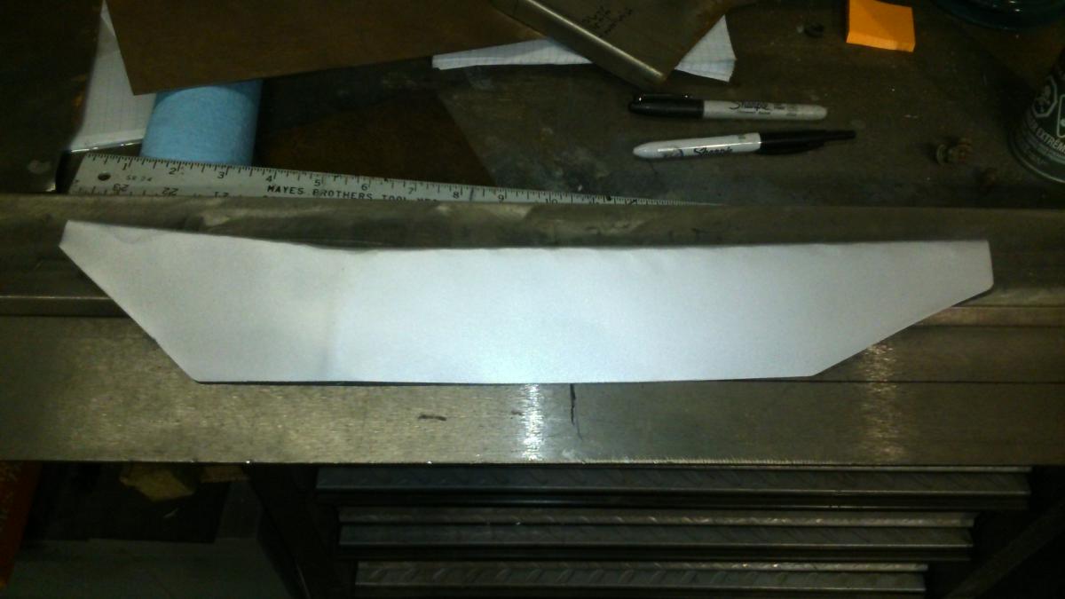
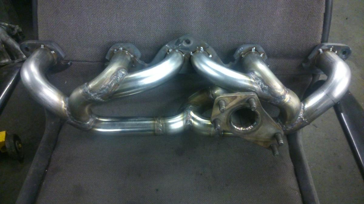
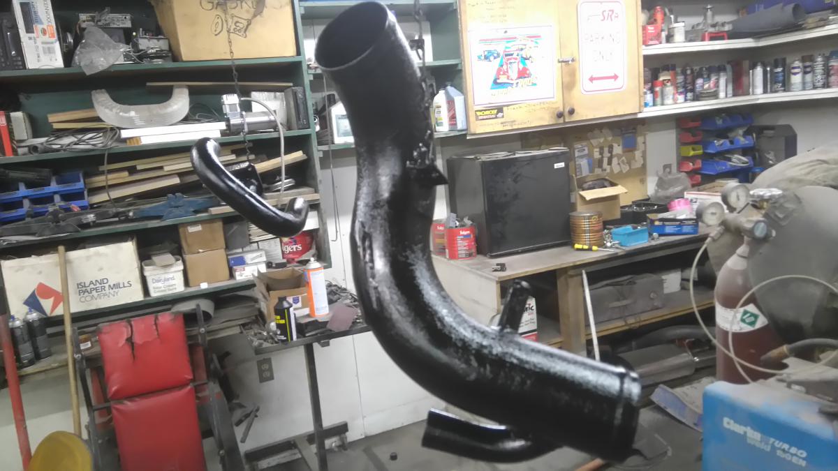
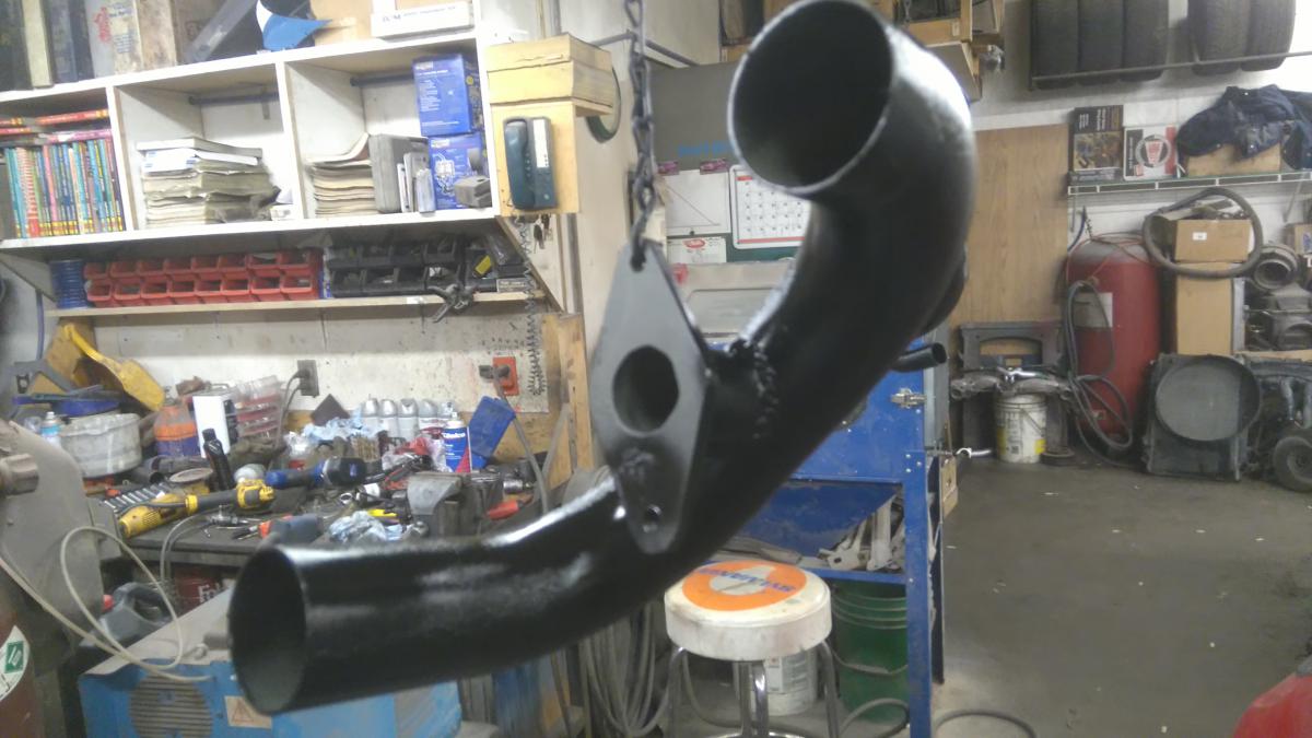
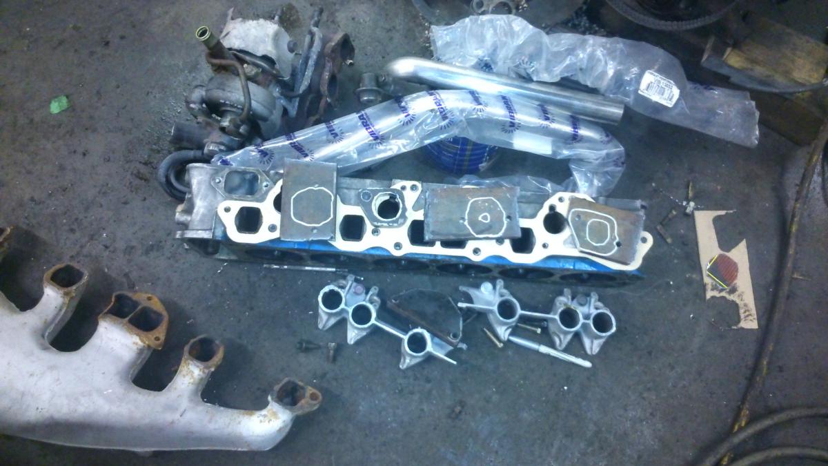
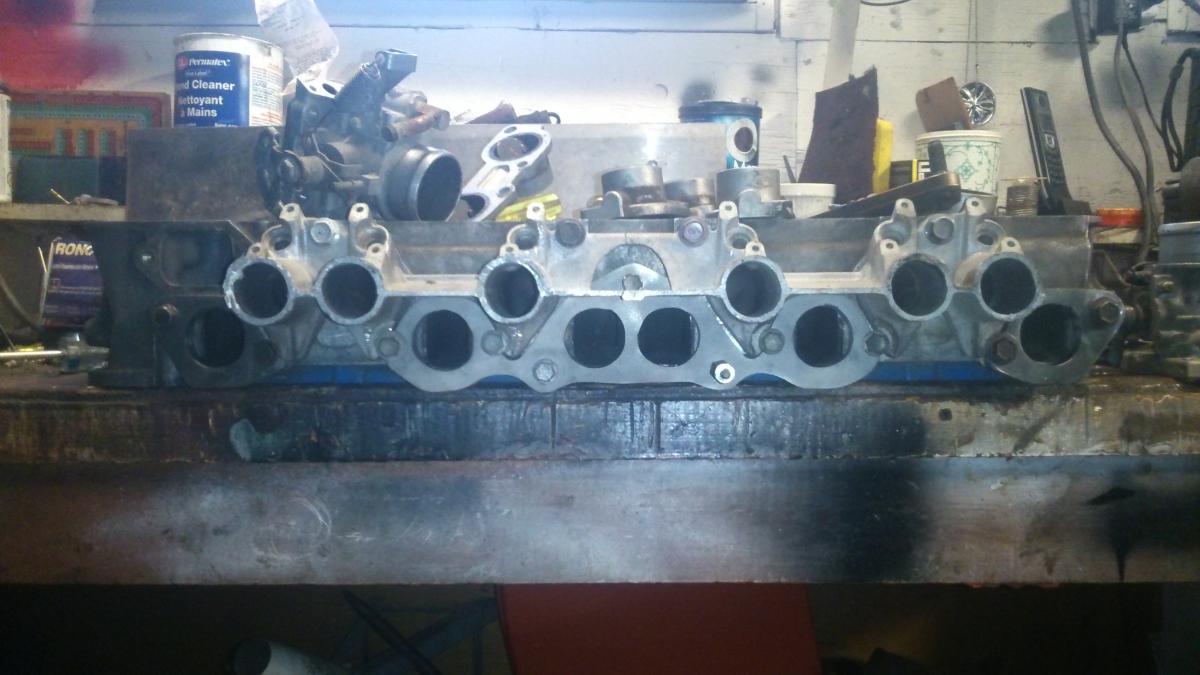
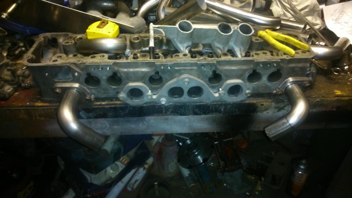
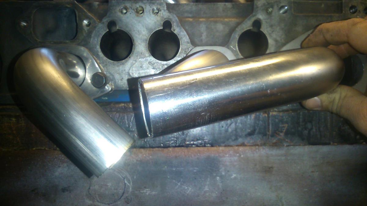
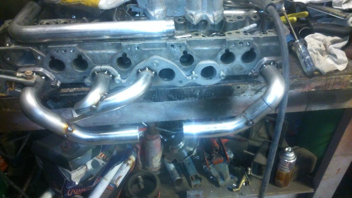
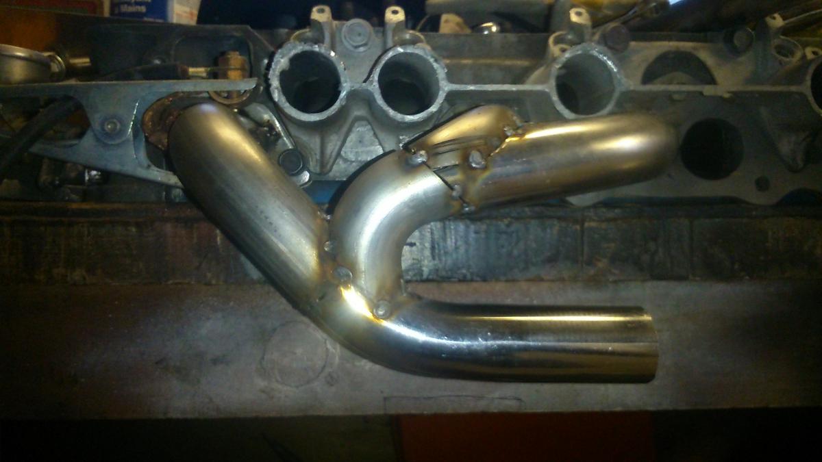
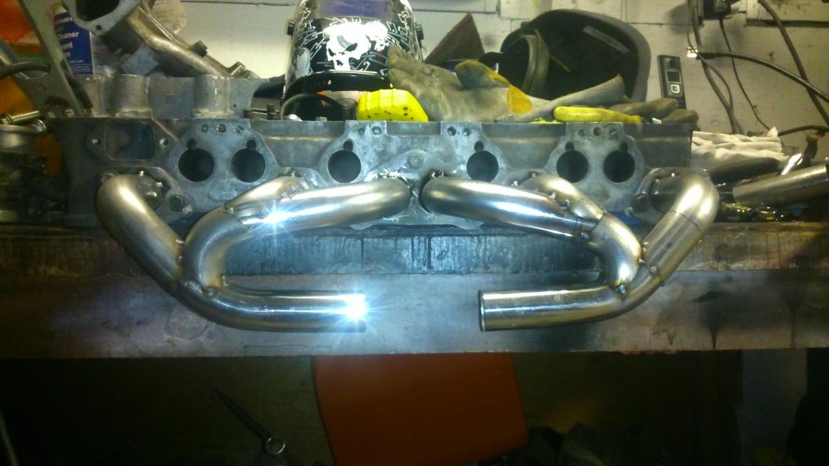
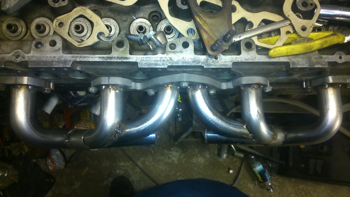
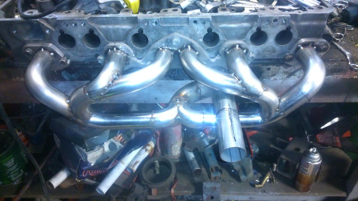
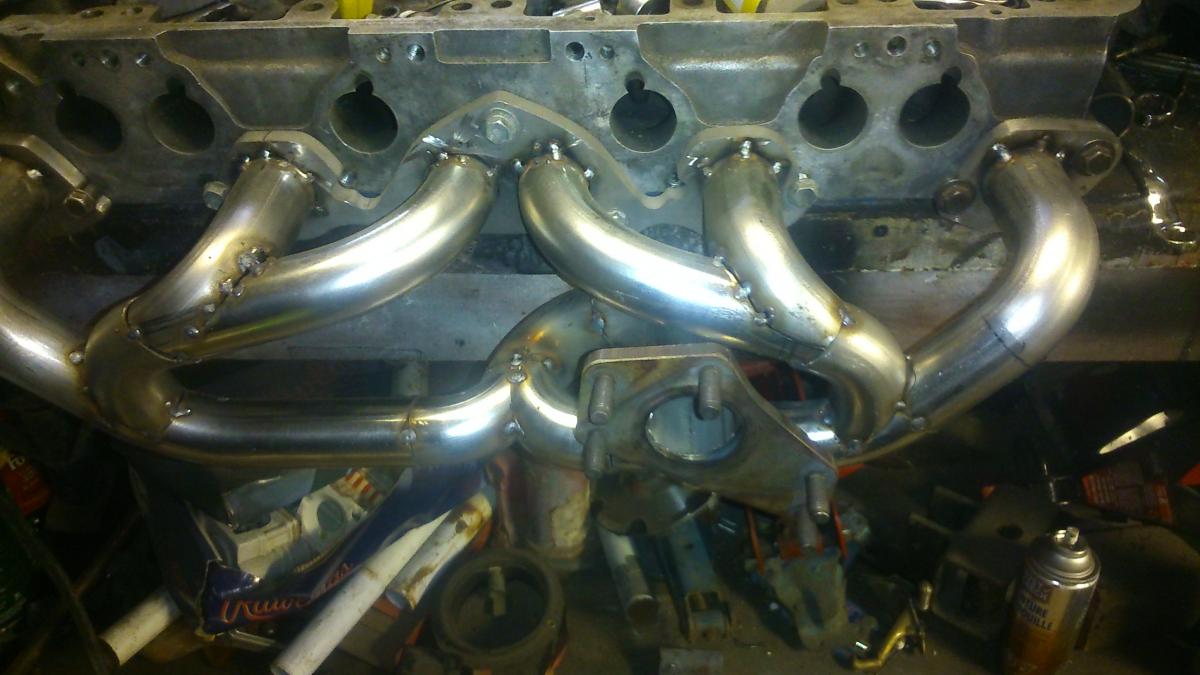
After about 5 years of tossing around the idea, asking people, doing research, I decided to finally tackle making my own exhaust manifold for the L28ET since I was rebuilding it, anyway. My goal was an exhaust manifold that was as equal-length as I could get it, with space being the main compromising hurdle. This is purely experimental, and I have no idea if there will be major gains with this setup. I'm not after huge power numbers, but I would like better turbo spool time, and not have a cummins exhaust note. Two of my friends helped with the manifold, one made me some flanges, and the other did the final TIG welding after I tacked it together with the MIG. Flanges made, using a beat-up N42 head as my template Also used a sawed-off efi manifold, and later, a spare, complete intake for clearance checks I started by angling runners 1 and 6 in a similar fashion as it would go with a low-hanging log manifold. Then, I ran runner 3 towards 1 at as close to a right angle as I could get, with the intention of joining them with a 90 degree bend, in the direction of exhaust flow. But not before joining it with runner 2, first. Like so. Then mirrored for the other side. Seen from above, I used a wider radius bend for runners 3 and 4, so they traveled a shorter distance from their respective ports to where they collected with 1-2 and 5-6. The runners are made using the Vibrant 1.5" stainless mandrel bends, and are joined in the main collector, which is comprised of 1.75" of the same material. Note how it loops around to exit at the turbo flange, which is close to the stock turbo location. A Subaru turbo flange was used, as that was the only turbo I had at the time. There is now an adapter bolted to it for a T3 flange, as I had found an RB25 series 1 turbo (not shown). The finished product is quite nice. A video of the sound and operation test is here. Any opinions/feedback from folks on here who have experience with this stuff is welcome.
-
Twin cam head for the L6 from Derek at Datsunworks
Barrel_Ball replied to Derek's topic in Nissan L6 Forum
I come back to this forum, after a year or two, and I find this thread. I'm in shock and awe of this engineering adventure! Love the fuel distribution block and injector caps on your engine, by the way. Very clever. -
I had this MS-II since 2011, it's on a V3.0 board, all the basic stuff, BIP373 ignitor and whatnot. I worked fine up until the end of last year before I removed it and all its harness from my old car. Hook it all up to my current project, hook up all the necessary powers, grounds, etc. I'm getting a consistent tach signal, as told by Tunerstudio and the sound of my injectors firing, but the spark happens very weak, and not consistent at all with the crank signal. I started with the coil - it was burned out, so I replaced it and the ballast resistor. No change. I trace all the wiring from the coil's negative lead, all the way back through the relay board, through to the BIP373. All good. So I figured: "I's gotta be the ignitor". I order one up, just installed it, still no dice. I even got consistent power to the coil positive lead when the ignition's on. What happens, is that you'll spin the dizzy shaft (L28ET with optical CAS), and all the coil does is nothing for a few seconds, then lets out a very weak spark once, then nothing. sometimes, it'll do it without any rpm input. I'm almost convinced the whole thing is fizzled out from the daughter card. Tach/input settings are as follows: Spark mode - Basic Trigger Trigger Angle/offset - 10 degrees HEI - off Skip pulses - 3 Input Capture - Rising Edge Spark output - Going High (inverted) Output pin - JS10 (properly jumper-wired, being what it is) Any ideas would be greatly welcome, as I'm at my wit's end.