

nmehdikh
-
Posts
82 -
Joined
-
Last visited
Content Type
Profiles
Forums
Blogs
Events
Gallery
Downloads
Store
Posts posted by nmehdikh
-
-
So I've been doing some reading on this, and I want to make sure I got my ducks in a row before I spend money on an adapter.
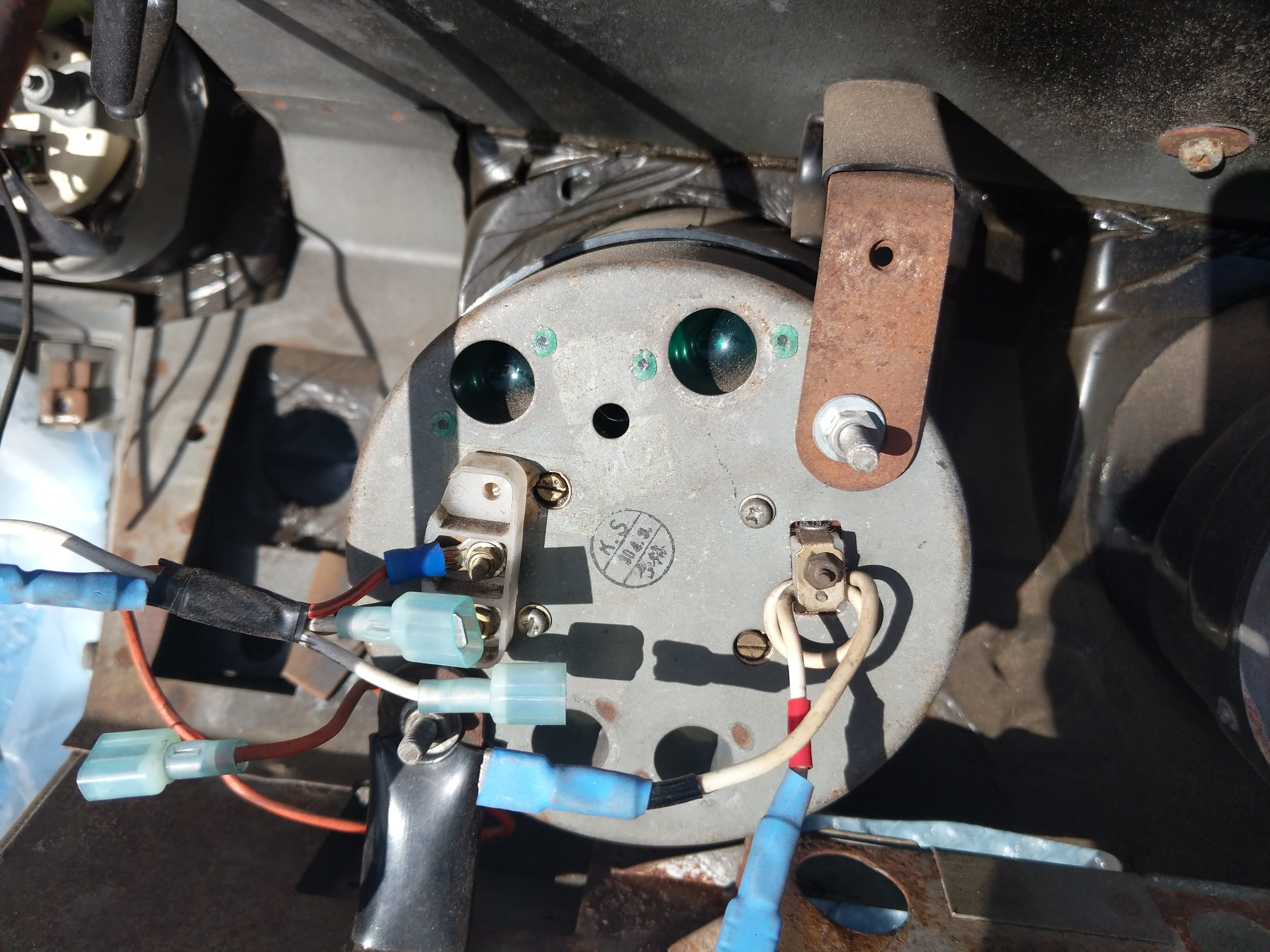
Car is a 1973 240z, being converted to MS3x 3.57. Factory wiring is gone, no coil etc. Here is a pic of my tach, which if I understand correctly is the current sensing type.
I've been reading this thread about using a MSD 8920 adaptor. And here is the manual provided by MSD
So from my understanding there are 4 wires on the MSD box.
1) Ground
2) Tach signal input
3) output to tach
4) violet (unused)
I connect the MS tach signal to wire #2. I take wire #3 and connect it to one end of the tach loop. I connect the other end of the tach loop to a +12v power when the car is running or starting. And I ground wire #1. Will this work?
The other option is using a TM-02-I from technoversions. The instruction manual can be found here.1) One end of tach "loop" connected to +12V when running or starting
2) Other end of tach loop connected to pin 3 on the tach adaptor (with or without power resistor?)
3) Pin 1 connected to +12V when running or starting
4) Pin 2 connected to ground5) Pin 5 connected to megasquirt tach output?
Also, on the technoversions adaptor manual, what is the difference between the two +12v sources?
-
I've been traveling for work the past few weeks so I haven't been able to get much done. But this weekend has been pretty productive.
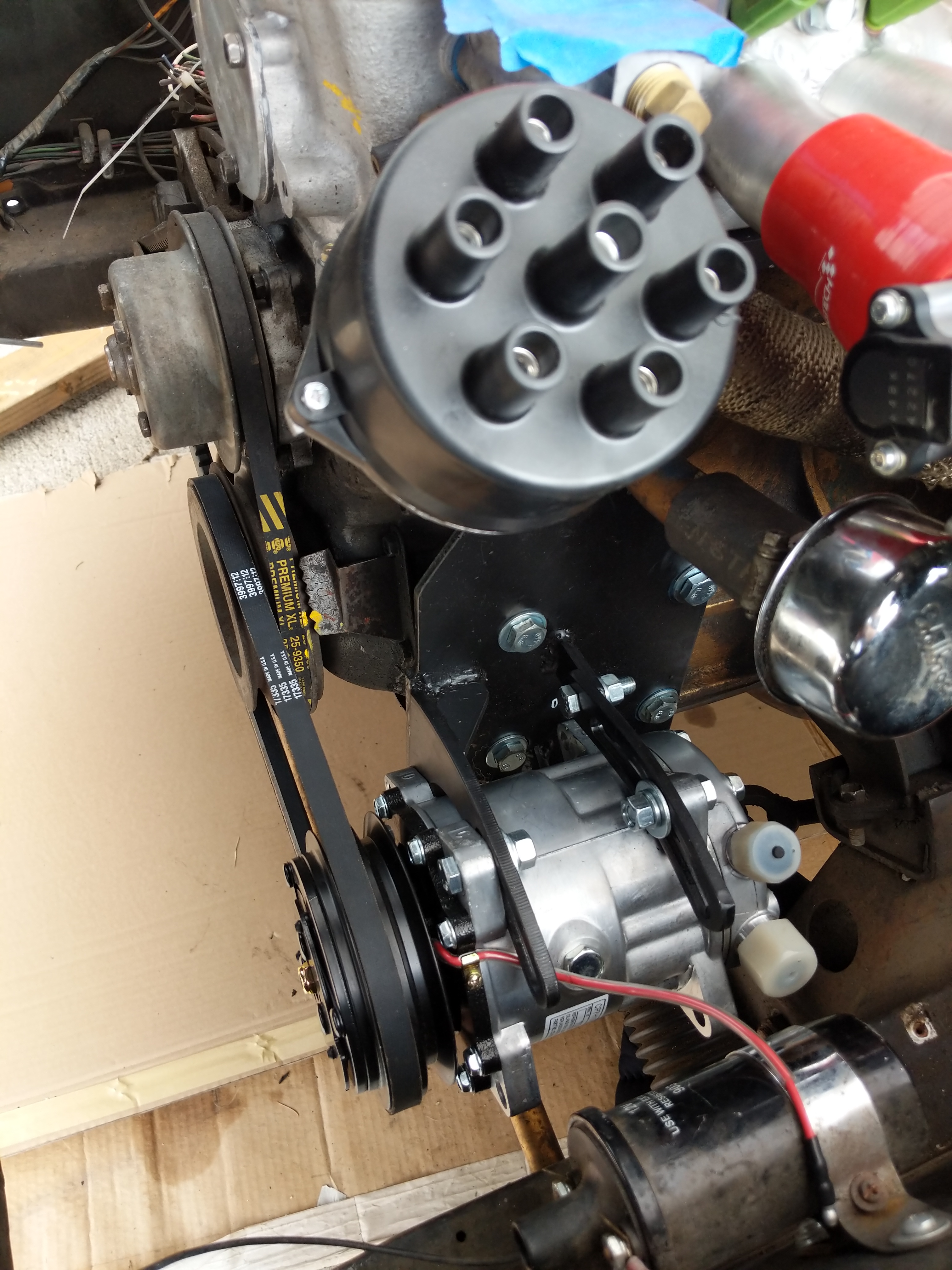
Got the distributor swapped over to the turbo distributor to give me crank angle and cam position. Got the AC compressor mounted as well.
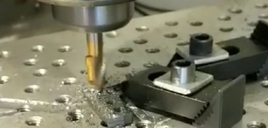
I had to CAD up and mill out a little bracket to adapt the throttle linkage to the factory triumph cable pull.
Here is the completed linkage and a crappy vertical video
-
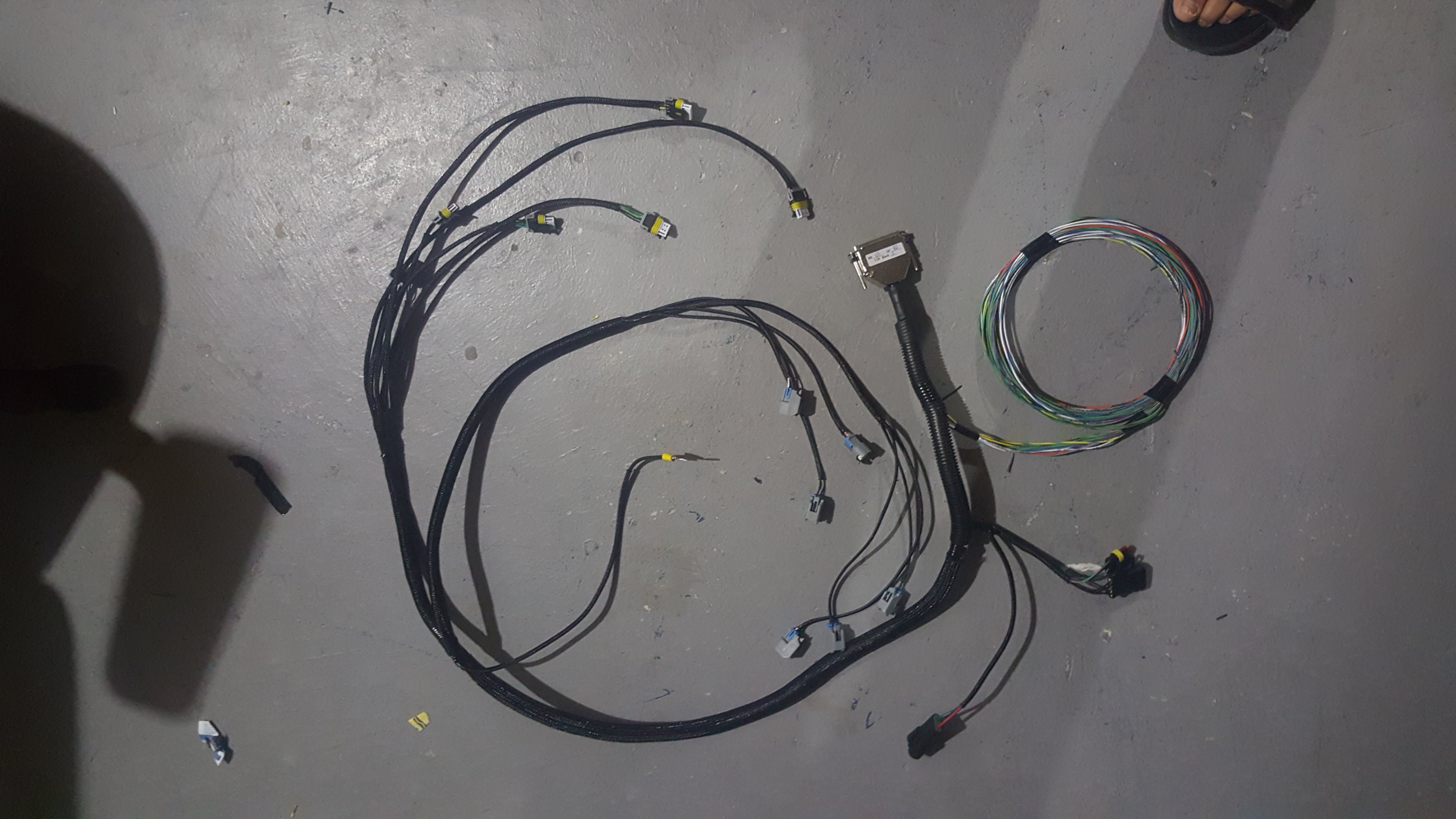
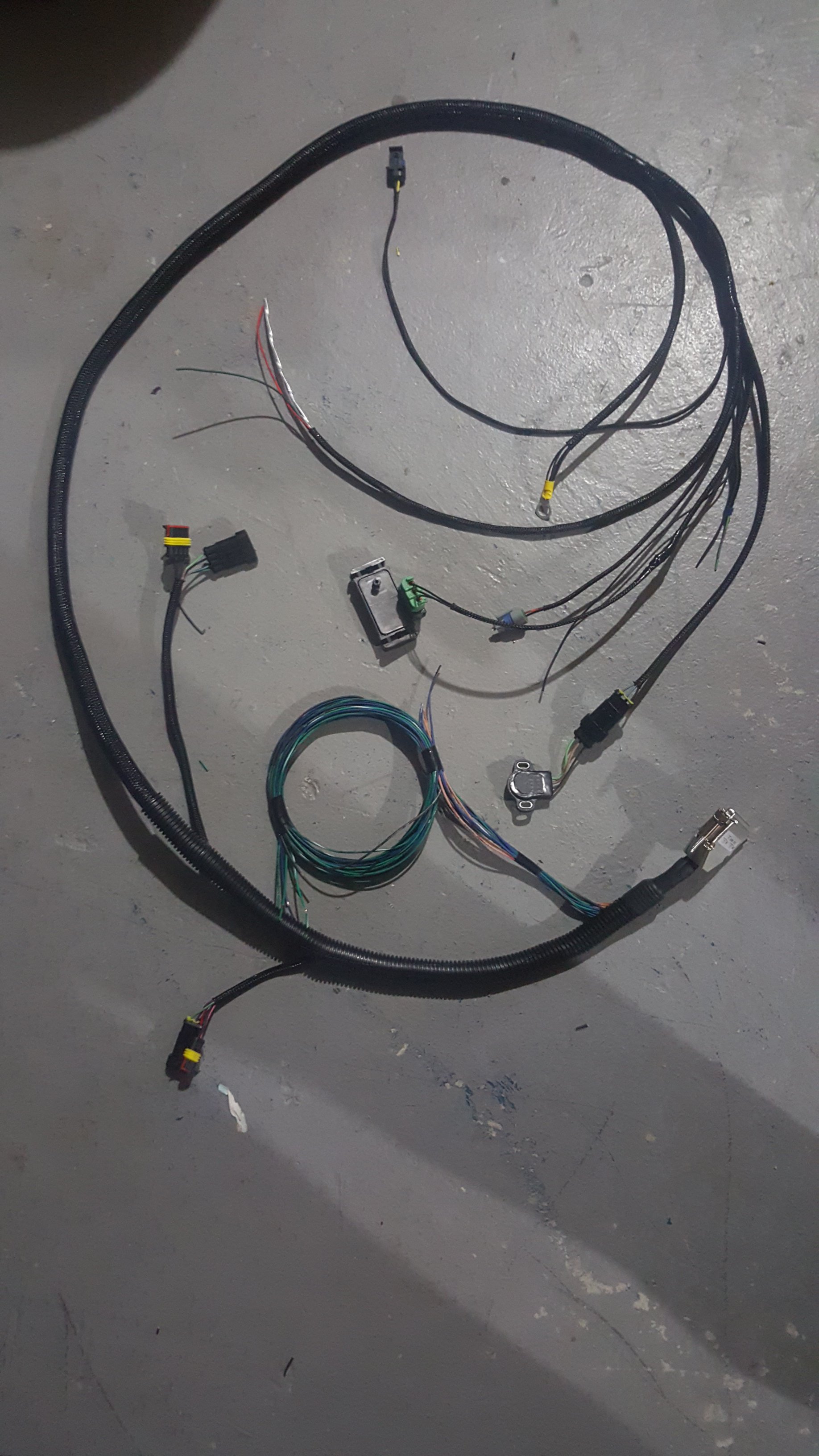
While I've been doing all this work on the car, I've been in contact with Softopz, and he's been making me a megasquirt harness for my needs. He recently sent me work in progress pics, and has been great to deal with. I'd highly recommend him if you are interested in going the megasquirt route.
Here is a link to his thread where he sells harnesses.
-
Thanks for the info guys. I appreciate it.
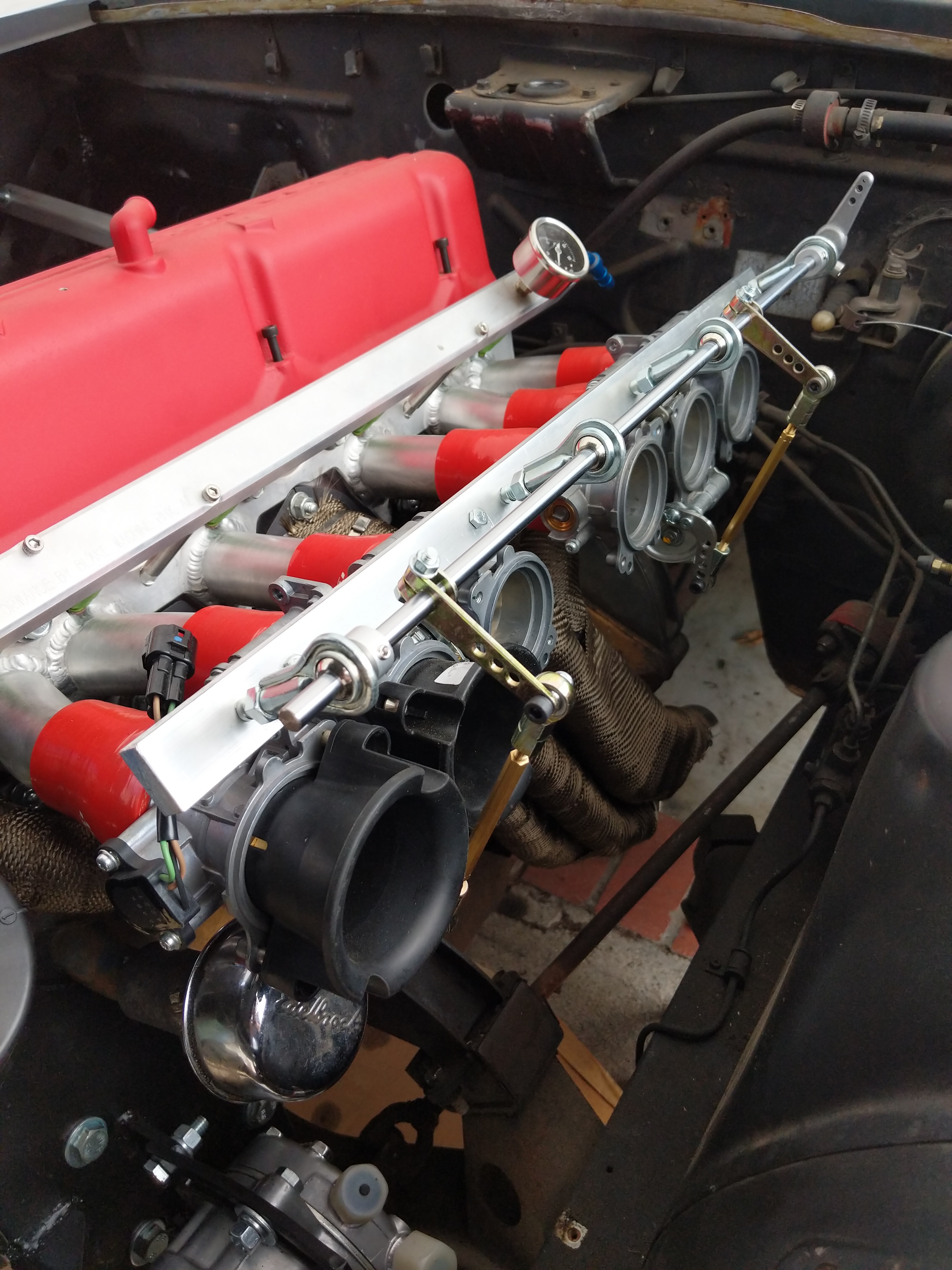
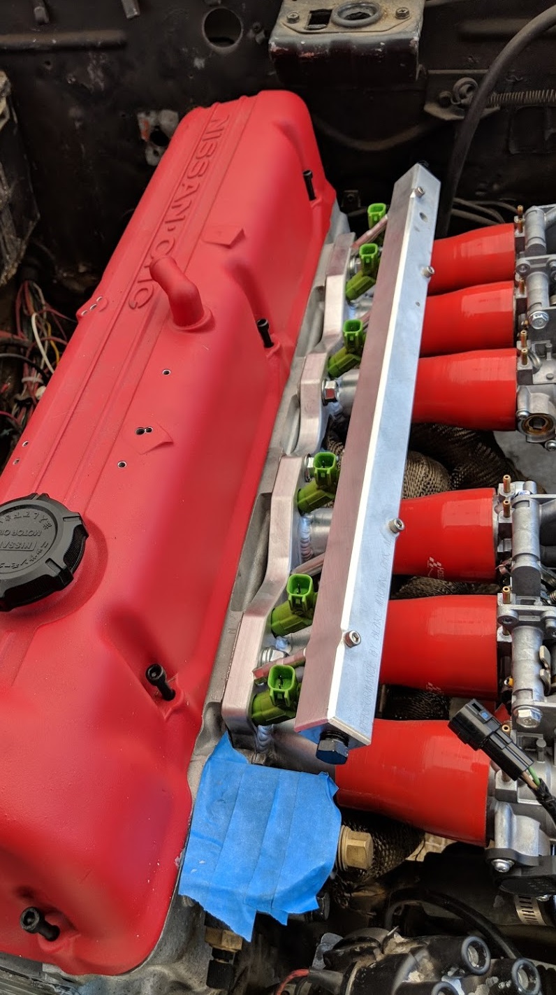
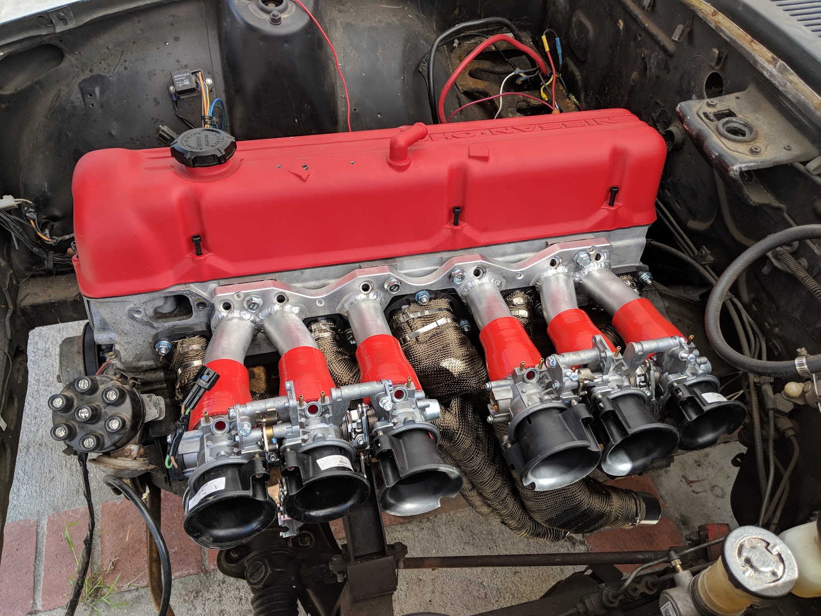
This weekend is pretty busy for me so I didn't have much time to work on the car. In the meantime, I finalized the header and intake install and they are on for good. I had to wait for a new gasket that arrived a couple days ago. I also got the thermostat housing on, and the fuel rail and injectors. The throttle bodies are still only on there temporarily.
-
On 2/13/2018 at 6:02 AM, Namor said:
You don't have AC though, right? How thick are the altima fans at the motor? I had a fan that was 3.5" thick at the motor and had to go to a thinner one because it interfered with my AC pulley.
It looks like it clears an AC pulley, but it seems like it might interfere with the belt / compressor. Hard to tell from the pics. -
I got a couple questions for you guys.
1) Since I'm going to be running LS coils, what kind of spark plugs should I run and at what gap?
2) Since I rebuild the head and it has a brand new cam, what break-in procedure do you guys recommend? And what oil should I run during break-in? -
Thanks a lot, those pics are very helpful!
-
On 2/4/2018 at 9:16 PM, TimZ said:
With an aggressive cam, you're likely always going to be on the low side for acceptable vacuum for the booster. A better solution for this would be to get an electric brake booster vacuum pump from any number of diesel cars out there. Wire it up with a hobbs switch to regulate the vaccum and you're good to go. Here's the pump that I use:
Did you also run a vacuum reservoir? Or are you just running the pump to the booster? -
It would be great if you can get a pic of the waterpump pulley as well as the AC pulleys. Also if you can, would you be able to measure the thickness of your radiator?
I have a similar setup, but slightly different radiator and am curious to see if I could fit the altima fans. Thanks. -
Started test fitting stuff to check clearances. Also got the fuel pump installed in the tank this weekend. Next weekend is probably going to be running fuel lines, while still procrastinating the mess that is wiring. I also need to get another set of triumph velocity stacks, because the two sets I have are currently mismatched...
-
How did you wire up the altima fans exactly? I recall they are a 4 wire plug due to high / low speed settings right? Are you just running high all the time?
And how tight is the fan against the motor? How's the clearance for the pulleys and belts? -
3 hours ago, Miles said:
What year Z would help.
You will need to keep line 8 and route it to where line 5 attaches to the filler neck in the picture below.
Look at the picture and you will see why you need to keep the line in addition to venting the tank on hot days.
Car is a 73 240z, sorry forgot to mention it.
I'm having trouble understanding why line 8 specifically gets connected to the filler neck. What's its specific purpose? Is it just so when I fill the tank full, the excess goes to the filler neck instead of the vent line?
My tanksinc pump sits on the flat portion between line 7 and line 8 if that makes any difference here.
1 hour ago, madkaw said:On my 71 , I ran the vent fitting on my Tank Inc in flex line all the way up front to the original vent valve on the fender .
My fender vent line is non existent, so I'm trying to figure out another solution. But thanks! -
So, I'm in the middle of converting my car to EFI/ITBs. I have a thread in the project forum. But I had a specific question about tank venting.
I'm running THIS tanks inc pump, which has it's own vent opening. I'm trying to get rid of whole evap tank system and trying to figure out what to plug, and what to route where.
A post in this thread suggests to only run rear tank pipe to the filler neck, then plug the rest of the tank fittings to get rid of the evap tank.
So what do I do here?
A : plug all the tank fittings, then run the tanks inc vent to the filler neck?
B : plug all the tank fittings except the rear one, run the rear to the filler neck, then vent the tanks inc somewhere else?
C : plug all the tank fittings, plug the filler neck fitting, and run the tanks inc vent somewhere else?
D : something else that I'm missing?
Also, does anyone make a line of fuel safe end caps for the tank openings? or do I have to do a stretch of fuel hose and bolt method? -
Thanks for the pics. I might copy your design for myself in the future if you don't mind.
-
I'm going to be plugging my old feed, return, and vent holes off the tank and using the stuff from the new pump mount. What are my options for plugging the openings? Are there any fuel safe rubber caps? Or do I have to go with the bolt clamped into a fuel hose method?
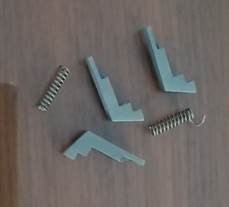
My datsun's mysterious history continues to baffle me. Started working on installing the fuel pump in the tank today. Cut open the top, cleaned it up etc. Found these guys rattling around inside the tank. No clue where they came from. Any ideas guys? -
6 hours ago, rossman said:
Is that silicone hose you are using to mount your ITBs to the manifold? I'm pretty sure fuel will break down the silicone.
Yes, its silicone hose, but the fuel injectors are down the line past the hoses and on the manifold flange. Do you think it would still cause problems? Worst case I can always weld it up, the hoses were about $20. -
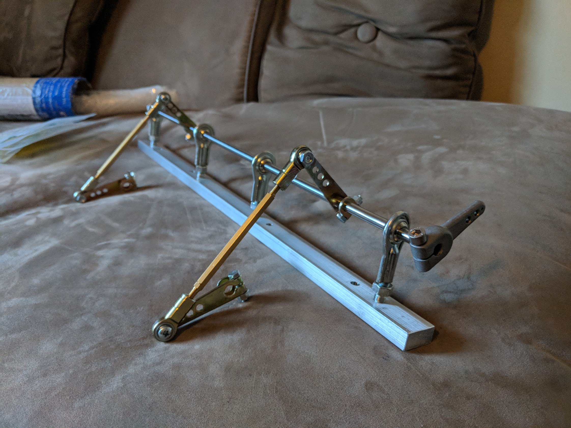
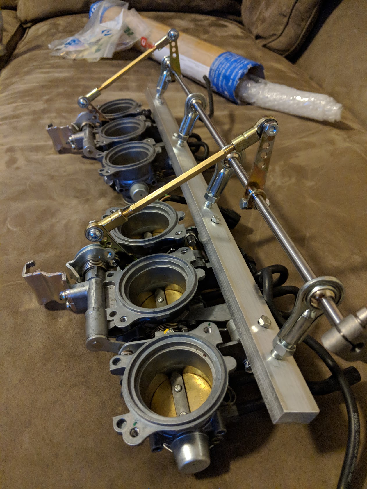
I spent this afternoon in the machine shop making a mount that would let me use existing holes in the triumph throttle bodies. Off of this mount I setup my throttle linkages and idler rod. Here is everything setup with a loose test fit. I still need to work on the sides of the droplink that connect to the triumph cable pull location.
-
I love your front splitter setup. Can you get some more pics of it? I'm trying to figure out how it's mounted underneath the car and where it pivots.
-
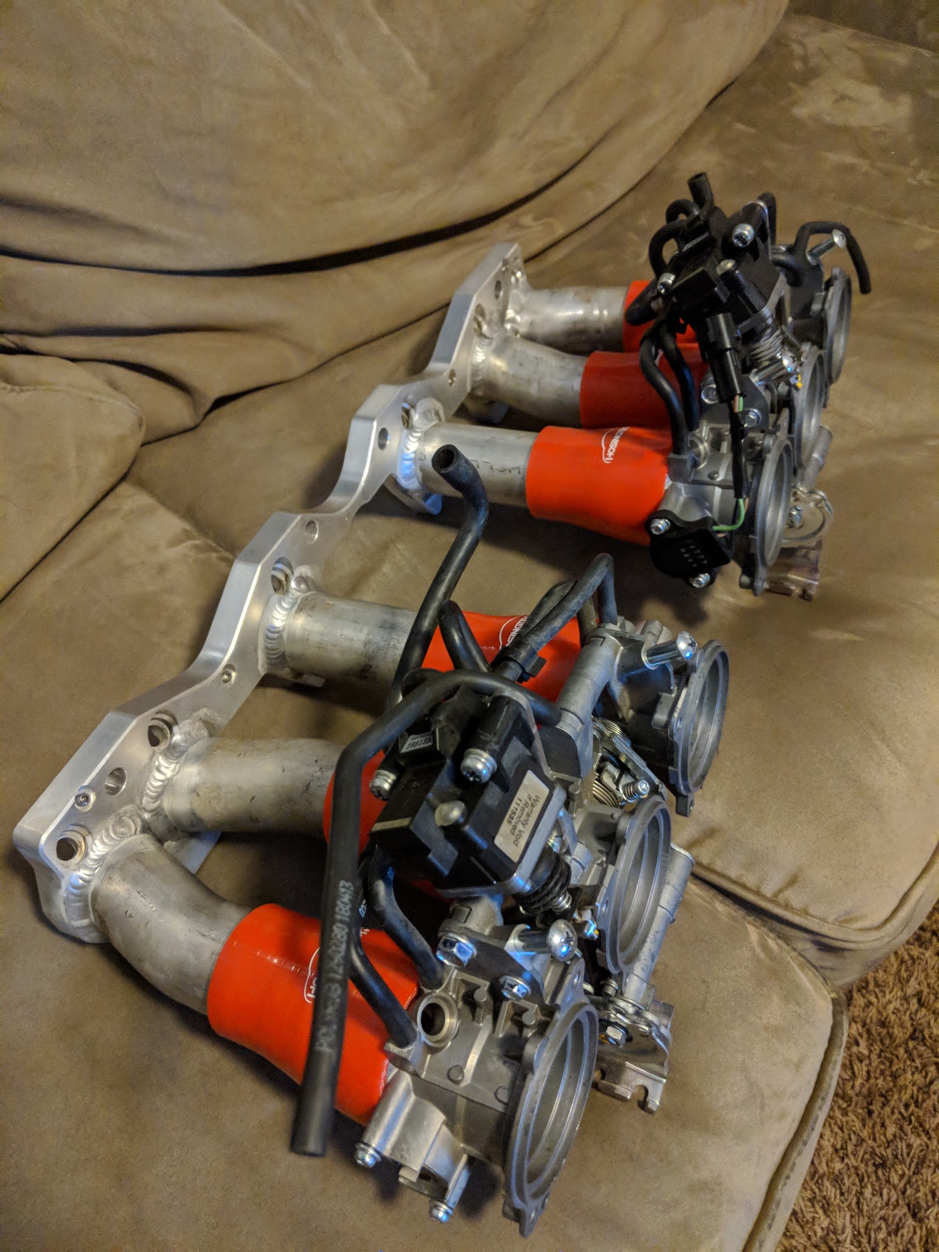
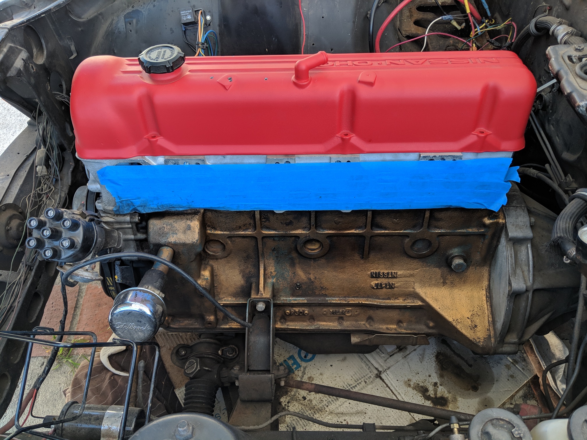
Got the head back on this past weekend. And just picked up the intake manifold from the welders. Next weekend should be test fitting some things and working more on the fuel system and wiring.
-
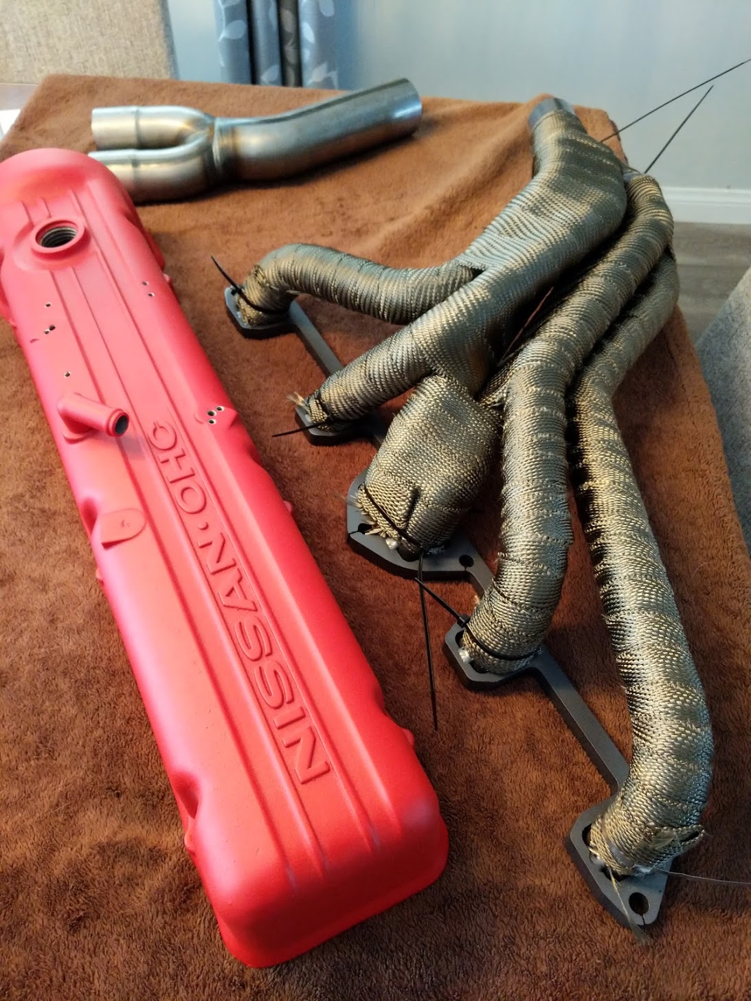
I had bought a new set of headers from top end performance, I took them in to be ceramic coated, and got the valve cover redone as well. Finished wrapping the header yesterday afternoon. Need to get proper metal ties for the header wrap.
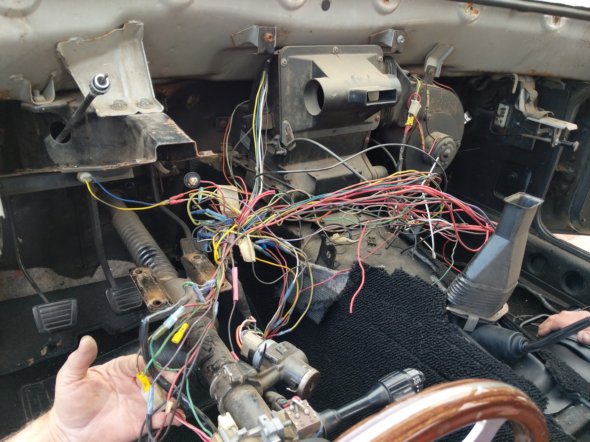
Also pulled the dash today to start on the wiring and vintage air setup. Long road ahead dealing with this rat's nest from the previous owner.
-
Thanks for the info. One more question, what front strut tower bar is that? And how does it mount to the firewall?
-
On 12/12/2017 at 5:03 AM, Richard Oben said:
We got the idea from another member here, can;t remember who it was but he had lots of problem with external pumps. In the end, it was not cheap doing the tanks inc pump. A couple of hundred in tank mods plus the pump. But I would do it again in a heartbeat. Everything is serviceable and sure you can hear the pump a little at start, after that it is like any other car. I am never worried about running the pump dry. There were a few decisions I would change but my goal on this project was to most of the stuff my self. Had the harness dieted and tank welded. I did everything else. HTH, Richard.
I'm looking to do the same pump, but why did you have to mod the tank? Was it clearance issues on the top of the tank? Or does the pump not reach the bottom of the tank? -
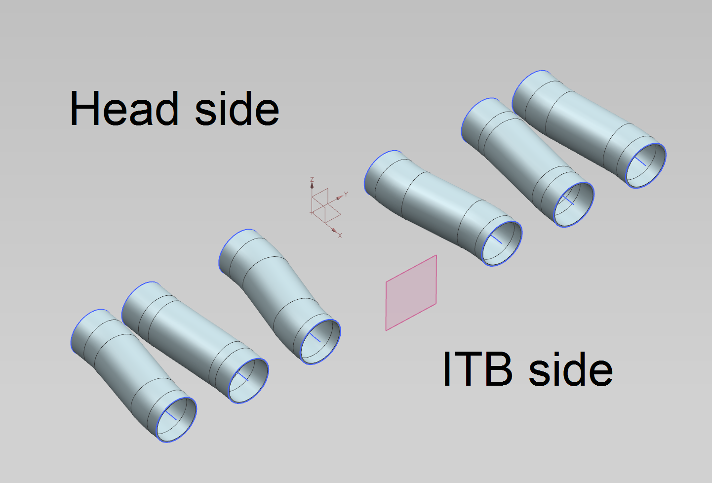
You are right about it not needing to be that precise. I CAD-ed them up so I could figure out the spacing of the two sets of ITBs relative to each other, while minimizing the offset of each individual runner. It was to give me a starting point before I start fabbing up the pipework by hand.
Got the gas tank out today. Going to clean it out and make sure all the fumes are out before I cut it open next weekend to install the new fuel pump. New camshaft / head parts should be here Tuesday, then I can take the head in to be rebuilt. -
On 1/4/2018 at 7:03 AM, bradyzq said:
Your seats are awesome, but for track duty, these days having a provision for a HANS device is becoming a no brainer. Second set of seats, maybe?
The seats were in the car when I bought it, and I agree. While they look great and are very comfortable for street driving, I am definitely going to get a dedicated track seat before taking the car out.
I had some free time today so I started CAD-ing up the tubing connections between the intake flange I have and the ITBs. Unfortunately, due to the spacing of the triumph ITBs and the spacing of the intake ports, its damn near impossible to get equal length runners. I need to go talk to some local aluminum tube bending companies and get their input on what's the best way to go about this.

current sensing tachometer
in MegaSquirt
Posted
While posting this I also emailed technoversions with my questions. He's currently looking into the MS manual about the tach signal output, but he believes that the tachoutput signal from MS should be enough to trigger his adapter. If that is the case, it can be wired up similarly to his diagrams.
I'll report back once he gets back to me. I'll make sure to document all of this after I get it working in-case someone has similar questions in the future.