Neubs
-
Posts
30 -
Joined
-
Last visited
-
Days Won
2
Content Type
Profiles
Forums
Blogs
Events
Gallery
Downloads
Store
Everything posted by Neubs
-
-
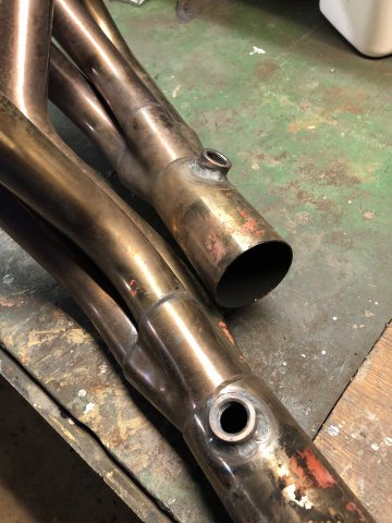
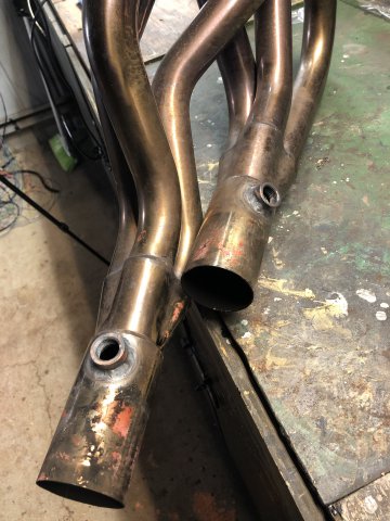
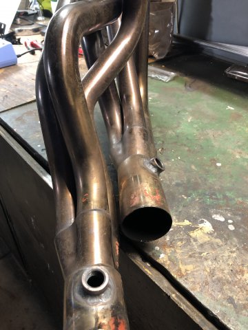
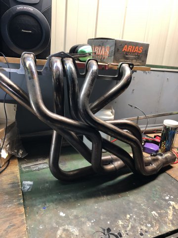
A little more has happened with the EFI build. Dual lambda sensors is what! I had planned to run dual lambda sensors on the Hitachi SU carbs if I had not the opportunity to work with Whitley Tune and the sport injection setup. The goal now is two injector banks with target AFR maps. I run a Zstory 6-2-1 header and I decided to locate the sensors at the collector of the primaries to mitigate the risk of air contamination through a joint. Its probably overkill but it seems sensible to have the most accurate reading possible if I’m trying to have the most accuracy target AFR map for two banks of injectors the MS1 V3 allows me to have. Cylinder 4-6 location was easy! The collector is located in the space between the gearbox and transmission tunnel. This one was near vertical which is the optimum orientation. Cylingders 1-3 collector is tucked in behind anything and I could to find an orientation that I was happen with to manage heat for the sensor and the wiring so I located on the side of the collector. The sensor and wiring is just in front of the gearbox in the space behind the sump. Its not completely horizontal but I’m confident its still in a good location. Innovate Motorsports recommend 24” from exhaust and these are about 35”. I’ve had an LM-2 for more than ten years and I plan to install a DLG-1 if it ever gets here (understandable shipping delay). Matt welded these bad boys in (MYS30 build - not sure if he’d on HybridZ?). I am in his debt .

-
Time for some Megasquirt ECU mods! I had configured the MS1 V3 board for ignition only. Some additional work and mods are needed to make it fully armed and operational for EFI. In the process I broke a leg off one of the current resisting devices for the injector banks I will have to buy new ones from DIYautotune as they are hard to get with the hole to mount on the heatsink. Thats really all that is left to complete on the ECU. In summary I've added: second WBO2 sensor input second Nissan optical trigger input fan relay control 2 wire IAC control shifted the launch control input 5V tach output There isn't many standard configurable pins left in the DB37 harness now.....
-
-
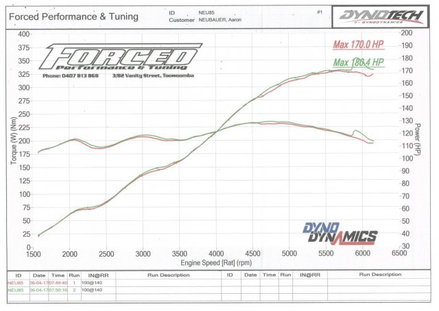
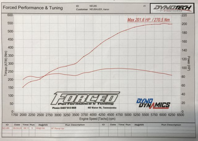
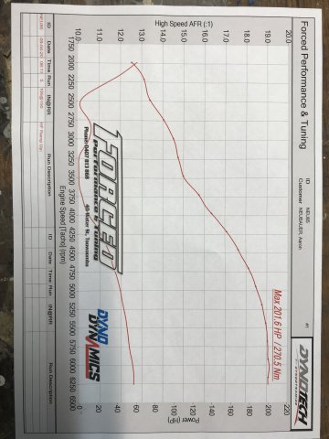
So, stock 4 screw round tops can support at least 201.6rwhp. There may be some debate over how the dyno calculates hp but there is a decent increase from the last dyno in hp and torque from essentially a tune to the fuel and ignition. Tune is super rich which could be fixed with different needles like TF but I wanted to get a run in in case QLD requires a lock down to manage the pandemic. I’m super chuffed. When I set out to home build the L28 stroker motor all I wanted as 200RWHP with triple Webers. To think I could achieve that with the standard carbs is amazing! I’ve attached the 2017 dyno sheet and the 2020 sheet. I can now get back to the ITB EFI swap knowing that it is likely to only make more power!
-
Hey all. A bit of time has past since my last post. Not a lot has progressed on the 240Z. Only a bit of refinement with the ignition map on the Megasquirt really. I’m almost happy enough to hit the same dyno to see if my tweaks pay off. I have had the suggestion of swapping out the SB needles to TF needles which I am contemplating but I want more logged data to inform my choice. With the time away from working on the car it has given me time to think. I’ve decided to convert to EFI. I’m excited to be working with Whitley Tune as a guinea pig for a future ‘Sports Injection’ kit for the L6. I’ve got a 3D printed test runner, throttle body and trumpet to clearance in the car. End to end it’s 410mm based on a third harmonic of approximately 5500 rpm. It is suitable for a second harmonic of approximately 7700rpm but I doubt building a head for that is in my capability but I might swap cam and work a head to be as efficient as possible for the third harmonic. Throttle bodies are Ø50mm straight bore butterfly. Have a look at the video below to get a feel for the runners, they’re a lot bigger in real life. The Megasquirt MS1 is pretty underpowered and can manage two banks of batch fire injectors at best. I will wire a bank of injectors corresponding with the banks of primary runners from my Zstory exhaust manifold using dual WBO2 to run closed loop target AFR maps. Ignition will remain as the 12-1 trigger disc L20ET distributor with MSD 6AL. I may change to COP at a later stage as an experiment but for now, if it isn’t broke don’t fix it. I am at a cross road for fuel supply. I have a Bosch 050 I had planned to use in conjunction with a surge tank and existing Holley Red as a lift pump. I have seen a few in tank EFI pump options. Has anyone used an aftermarket in tank pump? I’m interested in any experiences. The tank will come out for rehabilitation anyway. https://youtu.be/WtZvR__CQ3Q
-
I bit of perseverance (and a new CAS haha) has paid off! I have a functioning L20ET distributor that my Megasquirt MS1 can read. I fiddled with a few mods to the board taken from a few sites that have V3.0 board info. Ultimately I could have left the mods at removal of C12, C30, D1 and D2 but I left one of the diodes in as backflow protection. I didn’t need a pull up resistor but I left the one I had installed from the S12c pad. The Fuelmiser crank angle sensor Sparebox first sent was faulty through bench testing. Sparebox quickly replaced it which was great. I slapped the dizzy back together with the DYIAutoTune 12-1 trigger wheel which means I can run COP later if I choose. The next step for me is to swap in the turbo oil pump drive with the engine in the car. It’s the one item of work I have been putting off for obvious reasons haha!
-
Its always frustrating when things don’t go to plan. All the parts arrived to rebuild the distributor much faster than what I was advised and I had the dizzy housing PBM blasted and scrubbed to a raw appearance. I really like to look of the housing. I’m still hesitant to commmit to swapping the oil pump drive shaft to the turbo shaft until I know for certain that this dizzy works. So the dizzy was put back together and mock wired to the Megasquirt for an RPM signal simulation. No dice. Didn’t work. Nothing. I suspect the new crank angle sensor is not a functioning unit but will require more investigation. So looks like another few weeks without tuning the ignition for the car unless I put the old Pertronix L24 distributor back in. All I want to see is if I can crack 200rwhp on SU carbs....
-
Its been a while since my last post about this car. The brakes have been rebuilt. You can see those videos on the channel. In summary for the brakes: • Rear drum cylinders and MC were sent to South Coast Brake Resleevers • The MC was stuffed but the resleevers had a NOS MC lying around so I got that which I’m chuffed about! • Rear drum cylinders were resleeved to a high quality cause they were shagged • I rebuilt the front calipers myself So the brakes are on and bleed but I have not go little red off the blocks just yet. I really want to use the optical dizzy that Gav240z from the AusZCar forums gifted me (these are like rocking hose poo in Australia!). I had one big cost hang up that ultimately determine if I used the optical dizzy or used a CAS from One Six Industries and wastes spark and that was the turbo oil pump drive. Nissan dealerships and Nissan Australia parts had not had one in stock for over 20 years. Getting one from somewhere the US was pushing upwards of $200USD. I was getting sad. Lucky enough I came across a new product post from Kameari Raceworks who had decided to make there own when the genuine item price increased. The Kameari unit cost ¥11,000 which was heaps cheaper than any other pump drive and delivery wasn’t a lot from Japan to Australian. I put my order in and it turned up pretty quickly. So project optical distributor has commenced in full! See the video here:
-
Back to rebuilding the brake system this week. I decided to stick with drums on the rear. Having made that decision both the rear brake cylinders and brake MC will be sleeved to last longer than I will. So the rear brake cylinders and MC came out easy enough. The left side brake cylinder is properly frozen, not even the adjuster nut came out with ‘hammer time’ persuasion. I thought that I’d need to get new rear cylinders but after a chat with chap (after the youtube video was made) who will be handling the sleeving, the sleeving workshop can get anything apart. So rear brakes and MC have been posted away. I’m looking forward to the results!
-
I was going through my spares and came across some distributors from the Nissan RB30 motor. The RB30 SOHC motor is common in Australia used in the mid to late 80s and internally seems to be similar to all the distributor based ignitions at the time produced by Nissan. 280ZX turbo otipical dizzies are rare as hens teeth in Australia. I thought this would be a good substitute. I have a 12-1 replacement chopper disc from DIYAutoTune to replace the 360 slot standard one which could allow my to convert from the MSD unit to COP. Before I let my enthusiasm get the better of me I decided to check a few things first. Datsun 240Z L28 stroker – fitting an RB30 distributor - part 1
-
What started as a bleed of the brakes has evolved into a brake system rebuild. As long as I can remember the right drum brake cylinder bleed nipple has been sheared off at the base. It’s one of those things that I’ve know about but never actioned fobbing off to do it next time. No excuses now. Time to fix it. The end game brake goal for this car is a set of Sumitomo MK63 font calipers to retain the standard master cylinder. Not sure if vented or solid rotor. I guess this will be dependant on what’s available. I’m not in a rush to get a pair and considering it is likely to come from Japan I’ll wait until a good deal surfaces. I’ve have a spare pair of Sumitomo S16 cailpers and rebuild kits plus brake pads to cover off on the fronts. The rear drum brake cylinders look new so I’ll get some rebuild kits for those. The master cylinder I will remove and send away to be stainless steel sleeve which should make it good for life. I am bummed that tuning is on hold but it is important to have road worthy car.
-
Cheers! It’s nice to get feedback and I hope you enjoy the content.
-
Thanks for that. I currently have the trigger angle set to 0 degrees. Do you think this might be a problem? I have wondered if this may be a problem and have thought of shifting the leads around one location in the dizzy cap and setting the trigger angle to 60.
-
Following on from the strange ignition behaviour I thought it worth making up a cheap digital det can / engine stethoscope to aid in determining if something more serious was happening. I drew inspiration for an old Autospeed.com article I read probably around 2001. http://www.autospeed.com/cms/article.html?&A=0353 The basis was the Jaycar ‘bionic ear’ Short Circuits kit aimed at junior electronics. This kit had all I needed only requiring a few little bits and pieces to customise. The kit was assembled as per instructions and recommendations in the Short Circuits 2 guide. I simply lengthen the single core screened microphone cable and fixed it to a battery clamp. I tested it on my TD5 Defender daily and I could hear plenty of extra noises in that motor that’s for sure! As the kit uses a electret microphone it picked up all the noise. I think I will find it hard to isolate specific sounds, detonation being a primary one. For a first round its not bad though and I think I will gradually improve it over time such as switch to a piezo transducer and perhaps an alternate amplifier board. As soon as I can get some Penrite Super DOT 4 brake fluid to replace my stock and bleed the brakes, which is proving difficult in my ‘regional’ area, it’ll be road tuning time!
-
Off the back of pre-tuning experience I thought I’d combine the LM2 WBO2 into the Megasquirt so I could log all my data in Tunerstudio. Why have two screens to look at while tuning right? It was a pretty simply process simply wiring the analog output 1 from the LM2 to the DB37 harness. I did have to calibrate the Megasquirt to match the LM2 AFR outputs which I pulled form the LM2 using Logworks. The prefilled Innovate Motorsport WBO2 sensors in Tunerstudio did not match the LM2. I think it was 7.32 @ 0v and 22.39 @ 5v. So ready for some tuning. But first I want to make a digital det-can beforehand just to check the strange ignition behaviour of the motor. Stay tuned (pun intended).
-
Thanks @NewZed! The FSM I have doesn’t have that information. The original distributor was a D606-52 with a ‘6’ plate. I’m not fussed with the behaviour of the engine. I mean there are a hundred micro things that could be contributing. Proof will be in the pudding come dyno time. As long as the engine makes more power I’ll be happy.
-
So the little niggling issues continue. While travelling to a local informal coffee and cars show I discovered a problem with the ignition timing. It felt like an ignition ‘wall’ at around 3,400 RPM. My first thoughts were it was something other than the ignition advance. I’ve had 36 degrees in this motor when it ran the tripled 45DCOE152s years ago. I just assumed the engine could take the same again. I was going to check the signal form from the Pertronix in the event that signal noise was causing interference. I wasn’t real sure how to condition an I/O type signal. In the end it was the ignition advance. When the table ramped up to 31 degrees at 3,400 RPM, the engine couldn’t take it. Trialing lower advance in the same areas of the table allow the engine to rev properly. I’m glad it was an easy fix and I am surprised that with running the SUs with SB needles that the engine characteristics changed. A new chapter has been added to my ‘book of Datsun’. Anyway the ignition table has been revised to lower advance levels and hopefully this will be a suitable base for some road tuning. If anyone has come across changes in ignition behaviour with different setup ups, I’d love to hear it.
-
The moment of truth arrived for the first startup with the Megasquirt configured for ignition only and the SB needles in the SU carbs. The distributor needed to be aligned with the trigger angle parameter in the ECU which was easy to to. I did hit a road bump with a leak from a MAP vac hose that was larger than the onboard MAP sensor barb. That was fixed with a smaller vac hose 3mm in diameter from Super Cheap Auto. I had to buy the stand out blue coloured silicon stuff made by SAAS because the roll of non descipt black was empty. With the problem fixed the car runs but I want to revisit the ignition table before driving and adjust the SU mixture nuts after. The idle vacuum is a little different to what I thought it would be and revving the engine without load cause some hesitation around the 3k RPM mark which makes me think I have the advance ramping up too fast in the table.
-
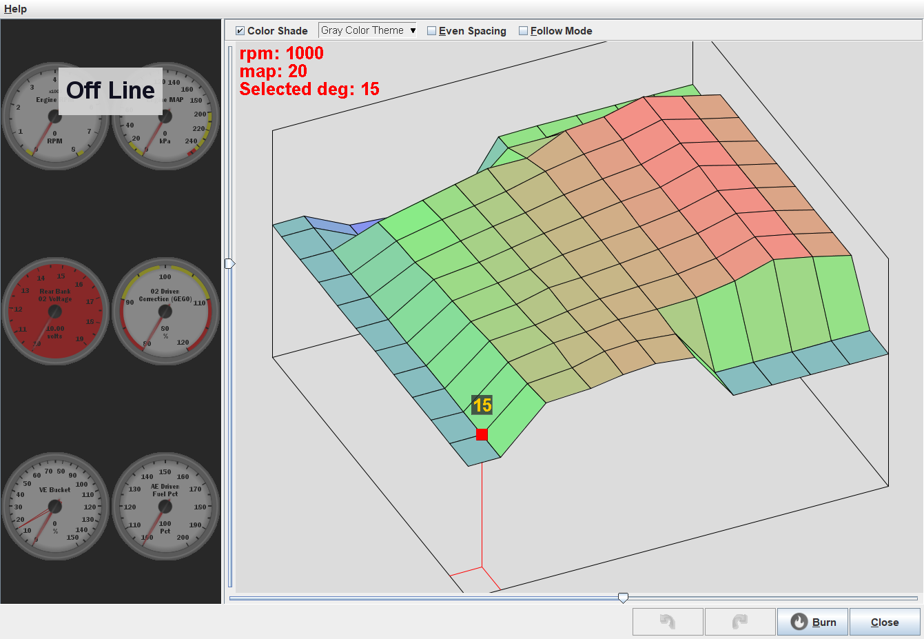
I was able to play home tuner using Tunerstudio to set put the parameters and rough in an ignition table for the MS1. There wasn’t a lot to set up with an ignition only configuration, the ECU is pretty under utilised as far as it’s overall capacity. Even though the hardware does not exist for the injector circuits, I zeroed the injector table data. To bench test the MS1, I used the Megastim board and a syringe with vacuum tube for the MAP. A 60ml syringe wasn’t big enough to generate enough vacuum to get to the closed throttle parts of the map but it was helpful still. I had help from Godzilla Raceworks who saw one of my Instagram posts and offered up an example tuning file from an MS2 used on a similar engine. I’m very appreciative for their assistance. https://www.godzillaraceworks.com/ There are a few items I need to address before attempting to start the car with the MS1 and new SU needles. The vacuum line for the MAP needs a home on the intake manifold and the signal wires from the Pertronix unit need a little tweaking to introduce voltage because the Pertronix unit doesn’t generate its only power, its only a switch essentially.
-
I snagged some time over the Christmas break to fault find the Megasquirt MS1 install. I 100% expected the problem to be something simple. Sometimes I hate it when I’m right… I hypothesised two possible problems. One being the ECU itself and the other the wiring loom. The ECU powered up and connected to the Tunerstudio when plugged into the Megastim board. Happy days that the ECU was not toast! This left the wiring harness. Voltage was getting to pin on the harness. That left that the harness was incorrectly made, that the voltage was going to the wrong pin. A quick review of my notes, physical verification and sure enough power was going to the wrong pin. A quick swap of the pin and the ECU powered up when connected to the wiring harness. I’m glad it was something minor and simple. Next stop, ECU tuning!
-
Finally got around to mucking with the megasquirt wiring harness. There isn’t a lot to wire up with the MS1 in ignition only configuration. It took nearly a week doing little bits here and there coming up to Christmas. It didn’t go to plan but the advantage of this being a project car is I can just shut up the garage until next year! Merry Christmas all and have a happy new year!
-
Mech advance in the distributor is locked! It’s slow progress but thats better than no progress. Next is wiring the megasquirt! I can’t wait to test the launch control feature and see if I can’t blow up the exhaust.... Share the vid if you know someone who might benefit from it.
-
I found some interesting parameters in the Tunerstudio software about launch control and flat shifting which got me thinking and consequently the megasquirt case hasn’t stayed assembled for long! I’ve build a protective circuit on the prototyping area to ground a 5v signal from JS11 leg of the CPU. This will be used to trigger launch control and flat shifting functions. I don’t know how this will function with the SU carbs as the MS1 is only controlling ignition. I suspect backfiring will ensue! I’ll have to build a clutch switch if launch control passes testing. I want the car to be about function not form. If the launch control doesn’t prove useful, I’ll bin it. Oh and the wiring loom of less than ten wires is also complete……
-
Slowing chipping away little by little. I mucked with the Megasquirt 1 this week. Got the V3.0 board sorted from where I left it two years ago from a full EFI build. Flashed MS/Extra and plugged it in to the PC with the stim board (after I installed the USB to RS232 driver for the cable ) and low and behold it worked first time! I'm pretty stoked that it worked. I don't have any special hardware built other than the standard configuration. It is literally taking the signal from the Pertronix unit and manifold pressure from the vacuum advance pickup and determining ignition advance from the ignition table. I will have to zero fill all the other tables. next step is get the wiring loom in order although I won't need a lot of wires for what I'm doing....