lifeprojectZ
-
Posts
49 -
Joined
-
Last visited
-
Days Won
2
Content Type
Profiles
Forums
Blogs
Events
Gallery
Downloads
Store
Everything posted by lifeprojectZ
-
AME complete chassis '77 280Z
lifeprojectZ replied to lifeprojectZ's topic in S30 Series - 240z, 260z, 280z
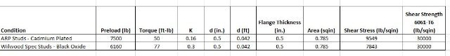
So I opened my Shigley and Mischke Mechanical Engineering Design and also my (preferred) Mechanical Engineering Reference Manual for the PE Exam. My quest is to get a better idea of what it would take to strip out the threads and if I would be close at the recommended torque. Easy formula: Preload = Torque / (K * Bolt Dia.). Getting the right K factor is the challenge. The K factor table in the Shigley and Mischke has black oxide at .3 and cadmium plated at .16, but I know that these may not be accurate for aluminum threads, as K factor is calculated from a more complicated formula with actual coefficients of friction. Nevertheless, I ran the following calcs which leave me 50% confident I didn't already screw up the aluminum threads, no pun intended. Next step will be to contact Wilwood to see if I can pry loose exactly the material spec of aluminum they use in their hubs, since it is not listed on their site, and then to contact ARP which appears by all accounts to be an industry expert in threaded fastener design and manufacture. I am guessing they will be more willing to help since I favored their studs over Wilwood's. In case you missed my earlier post, I changed out the Wilwood black oxide studs for ARP cadmium plated ones, due to a personal opinion that black oxide fasteners in aluminum is bad practice.
-
AME complete chassis '77 280Z
lifeprojectZ replied to lifeprojectZ's topic in S30 Series - 240z, 260z, 280z
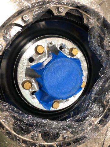
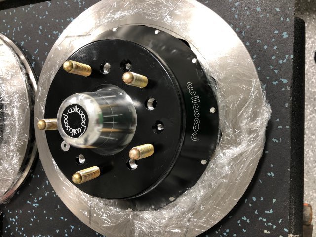
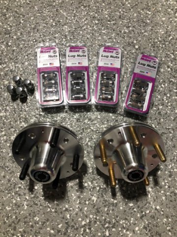
Pictures attached. They are the wheel lug studs that thread into the Wilwood aluminum hubs. These studs just thread in through the back side instead of being pressed in with splines.
-
big block Z, "across the centuries"
lifeprojectZ replied to Michael's topic in S30 Series - 240z, 260z, 280z
According to an old file I saved, it was sjorlin. This was a carry over from the Usenet newsgroups of the 90's. I don't know about the Miata, but my Z has garnered a lot of comments, even as a shell on a trailer when I towed it from Ohio to South Carolina a few years ago. I couldn't believe how many people approached me about it and told me they liked it. Gutted interior, no engine... I can't imagine the comments I will get when the car is driveable. I know apartment living well. Hopefully you find a garage or friend's garage soon, and are able to keep it from being stolen. I would think there would be a high risk of that in LA. -
AME complete chassis '77 280Z
lifeprojectZ replied to lifeprojectZ's topic in S30 Series - 240z, 260z, 280z
The OEM's (Wilwood) instruction sheet for assembling these hubs specifically states to torque the studs to 77 ft-lbs, and I have found other similar specs published for aluminum female threads with 1/2-20 grade 8 bolts (the wheel studs are actually stronger than grade 8). My feel on the torque wrench today is what gave me pause to stop and challenge this and ask for others' experience. I am a PE and capable of calculating the average stress on the aluminum threads assuming a value for the constant used in the calculations. Admittedly I haven't done that yet - LAZY! However I also remember from engineering school (strange I remember anything) that the stress in reality is greater in the entrance threads because the bolt stretches as you tighten it. So even the best calculations may not align with test data / real life. I can just imagine Wilwood's response to me calling over this, as I already called their tech line previously about another matter and found them useless in that instance. I will do it nonetheless and see what they have to say. I might be worried over nothing. -
AME complete chassis '77 280Z
lifeprojectZ replied to lifeprojectZ's topic in S30 Series - 240z, 260z, 280z
Ouch, I hope not! I want to get thoughts, opinions and questions through sharing my progress, as I know that will make me consider my steps more carefully and ultimately make the project better. I can think through many things on my own, but the experience of those here who have already modified their Z's and raced them is invaluable to me. I've done a lot of reading and research over the years including on this site, but have put off the doing until now.... Thanks for your comments. More to come... -
big block Z, "across the centuries"
lifeprojectZ replied to Michael's topic in S30 Series - 240z, 260z, 280z
I joined this site when it was first created but under a different username. I can't even remember, like many things from 20 years ago. Work and life took me away from my Z while it sat original and untouched in storage the past 20 years. I remember a lot of the earlier threads, and have also noticed some significant changes as a generation has passed. Michael- I am excited about your big block Z, please keep us updated on your technical progress to make it great. Dig into it yourself as much as you can. Nothing quite like hearing a big block with a race cam pull up next to you, no matter what it is in! In my view, the Z is a great canvas and we the artists should "paint" it however we want. My project, detailed in a separate thread here, has taken many turns over the years, but I also have never let go of it. Long live the HybridZ! -
AME complete chassis '77 280Z
lifeprojectZ replied to lifeprojectZ's topic in S30 Series - 240z, 260z, 280z
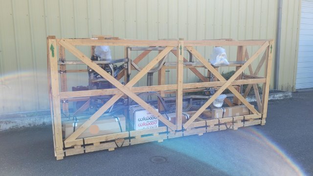
Chassis on the way and first problem with Wilwood parts. The chassis shipped out from Art Morrison on Thursday and tentative delivery is next Thursday, so I am getting ready to receive it, transport home and uncrate in the driveway. I'm building the front hub/rotor assemblies now, and ran into my first problem with the Wilwood parts. The little 1/4-20 countersink screws that hold the rotor hats to the wheel hubs protrude from the rotor hat by about 0.005". Even torqued to spec, they do not sit flush or below surface, so these would create a stand off from the wheel hub mating flush with the hat. Very frustrating. I thought for a few minutes about calling Wilwood over this, but I can only imagine the circus that would ensue. Temporarily, I took two screws and sanded down the flat heads to remove just enough material so they sit below the rotor hat surface, one for each hub. These screws look cheap and have what looks like a hot galvanized coating. The Wilwood package says they are zinc plated, but they aren't shiny and don't look like normal zinc plated fasteners. I found the same screws in 304 stainless on www.boltdepot.com, so I am going to get some replacements coming and have a friend machine down the heads slightly so they don't protrude and cause problems with wheel mounting. I started to torque the screw-in wheel studs into the backside of the wheel hubs, and got very nervous about stripping threads. Spec is 77 ft-lbs, and it just felt like the studs were turning too much after making contact, so I stopped at 50 ft-lbs. I might call Wilwood about this. Anyone reading have any similar experience torqueing into aluminum threads? The studs are 1/2-20.
-
AME complete chassis '77 280Z
lifeprojectZ replied to lifeprojectZ's topic in S30 Series - 240z, 260z, 280z
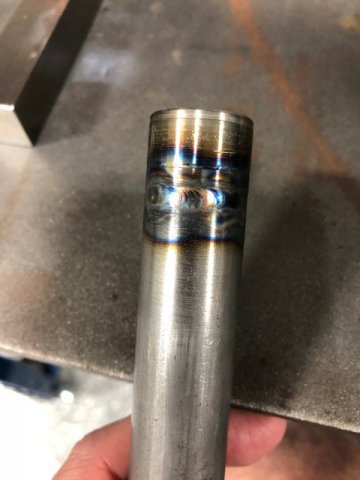
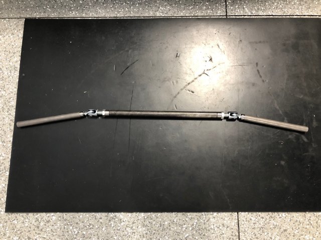
I'm still confused on this myself. There is at least one youtube video from Forgeline in which they say that their wheels are hub centric, and I take that to mean they are centered on the pilot bore. I wouldn't think you would want to do that with conical lug seats which will naturally seat the wheel when the lugs are tightened. Really, the lug hole circle in the wheel should be "perfectly" concentric with the pilot bore if the wheel was machined correctly, so I guess it shouldn't matter. My Toyota vehicles use straight shank style lug nuts with flat washers, so I am guessing they are centered off the pilot. I may yank one of those off to check pilot bore and hub pilot dia. just for curiosity sake to see what the design clearance is. After some very brief TIG practice and a lot of reading and watching videos, I started to weld the threaded tube ends on the steering rack simulator adjuster sleeves. The photo attached was with no filler rod and went pretty smooth. On the other end the tube end is thicker and I am having more trouble blowing out the thinner tube metal from the puddle, so today I will try running up the amperage a little, adjusting arc focus on the thicker material, and adding filler to see if I can get those to come together. I am a welding novice, and will have to get significantly better before I do any welding that counts!
-
AME complete chassis '77 280Z
lifeprojectZ replied to lifeprojectZ's topic in S30 Series - 240z, 260z, 280z
For the rear brakes I ended up going with the 2010-2015 Camaro standard rear brake setup with OEM cast iron rotors (12.4") with parking brake hub and floating single piston calipers. (The knuckles are OE from the 2010-2015 Camaro). This was really the only option that matched the front brake setup with the 12.88 rotors / 6 piston calipers. Apparently these rotors have a center pilot hole machind out to 2.783" to ride over a diameter of 2.780 on the wheel hub pilot shoulder which for some reason they are using from a C6 Corvette. This is slightly larger in diameter than the nose of the pilot which goes into the wheel center hole, which AME told me is 2.760. I spoke with sales guy at Art Morrison again today, and the chassis is supposed to be ready to ship in 1-3 weeks now, so time to start clearing space in the garage! -
AME complete chassis '77 280Z
lifeprojectZ replied to lifeprojectZ's topic in S30 Series - 240z, 260z, 280z
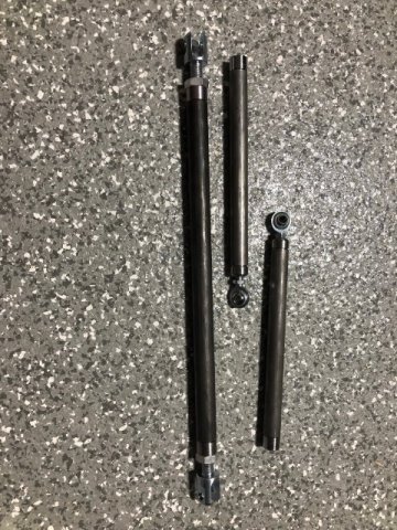
Tough nuts. Not much Datsun progress in the last few months. Just a lot of worrying about how the steering rack and engine mounting will come together in the new chassis, and clearance for even custom headers with the new upper control arm mounts on the frame rails. ....Had to get lug nuts to mount the wheels to the chassis once I unload it in the driveway, so I bought Mcgard tough nuts, having some good experience with them in the past. I also decided to upgrade the front wheel hub studs from the Wilwood kit (black oxide) to ARP studs which are cadmium plated. I haven't had any good experience with anything black oxide coated not rusting and causing grief eventually, so I didn't really like the idea of using them. Yesterday I called Art Morrison and discovered my frame has been completely welded and was quality checked that morning. So after paying off the balance next week, they will mount the F/R suspensions and I am supposed to take delivery about mid-September, which is right on the 6 month window they quoted me back in March, so I am quite happy with that. This summer was extremely hot and humid in S. Carolina, and with temps in the upper 80's in my garage I haven't felt like welding too much, so I still need to finish my steering rack simulator, photo below, which I designed with DOM tubing, threaded tube ends, rod ends, and two birdcage clevises. Nominally the rack length (pivot to pivot) is 21.5" which was what AME specified, but I made it such that I can shrink that pivot distance if needed to improve bump steer. My plan is to play with the mounting position and pivot-to-pivot length to dial in both bump steer and Ackermann geometry before ordering the Woodward rack. I ran into what could be an issue with the rear wheels. The pilot bores are 2.768", and the pilot stubs on the rear wheel hubs are 2.760". When I gave the specs to the dealer to order the wheels, I gave the 2.76" dimension, but it seems to me like someone either misunderstood this or didn't leave enough clearance. I wrote back to Forgeline, and the sales rep confirmed to me that for a pilot stub dia. of 2.76" they would have machined the bore to 2.78". That seems more reasonable to me. So now I am thinking about using a ridge reamer to open up these bores. Any thoughts / comments / experiences appreciated. I am thinking it will be difficult to mount wheels with only .004" radial clearance in the pilot, and over time the aluminum may seize to the steel hubs. But maybe I am overthinking things.
-
AME complete chassis '77 280Z
lifeprojectZ replied to lifeprojectZ's topic in S30 Series - 240z, 260z, 280z
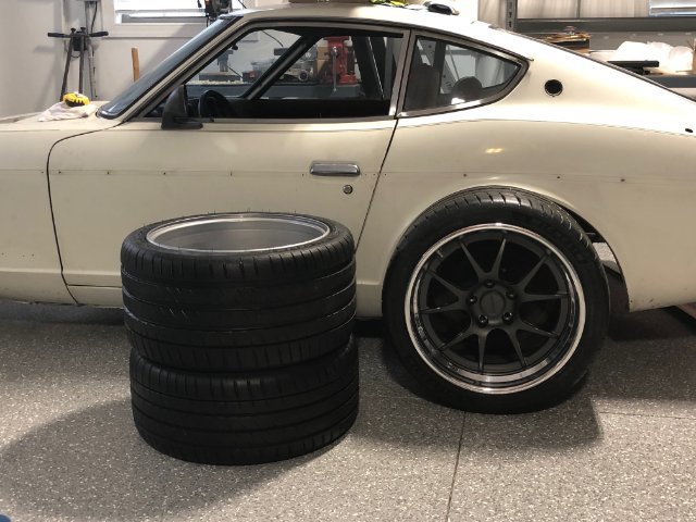
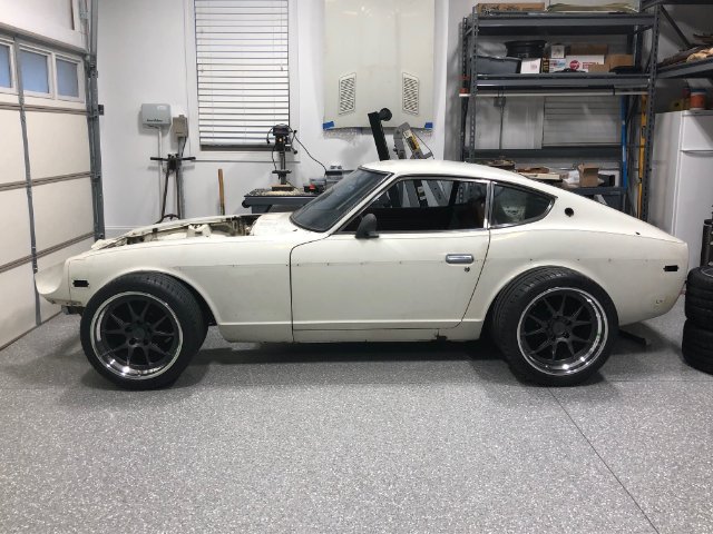
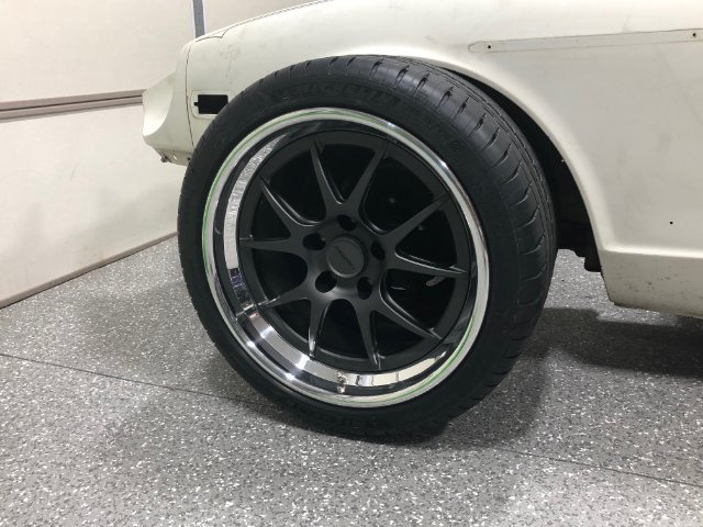
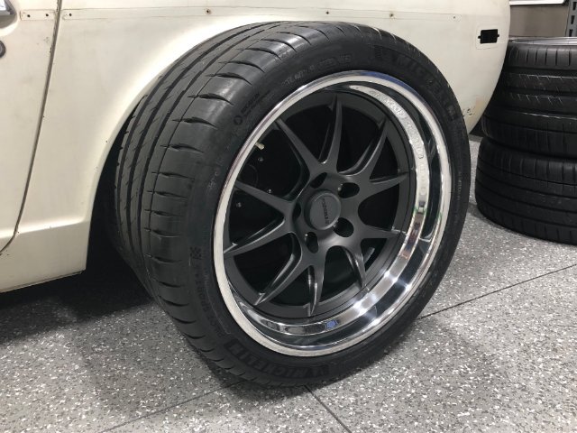
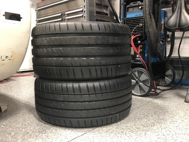
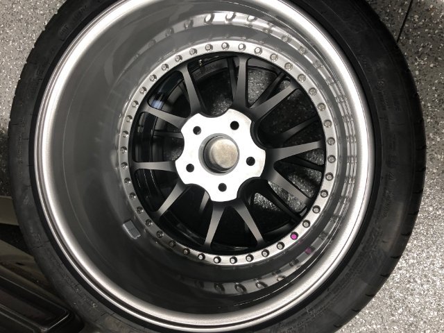
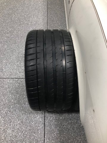
I’ll have a Fat Tire please. My wheels and tires arrived this past week. Here are the specs: Front: Forgeline GA3 18x9 with 5.5” backspacing. 5 x 4.75” bolt pattern. Michellin PS4 255/35ZR18 Rear: Forgeline GA3 18x10.5 with 7” backspacing. 5 x 4.75” bolt pattern. Michellin PS4 295/30ZR18 I spent no less than 20 years thinking about tires and wheels for my car. For a long time I was leaning toward 17” wheels and thought that this size looked the best aesthetically. But once I started designing the custom chassis earlier this year, I had to finalize the decision. So I looked for every photo I could find online of tire/wheel sizes for a Z car, and also examined tire sizes online to see what was commonly available and the price tag thinking about replacements in the future. I considered square setups and staggered setups with different tire sizes front / rear. I decided early on that I wanted to keep overall tire diameter in front and rear as close as possible to OE, for handling, balance, and overall packaging concerns. OE tire dia. is about 24.6”. A lot of tires being used on these cars, like the 275/40R17 look too large on the car for my liking. That tire is a full 1” larger in diameter than OE. So for a good while I thought I would go with 255/40R17 on all four corners, at 25” diameter. As I thought more about this and came closer to the time I needed to lock down the decision, I moved in favor of the larger 18” setup, primarily to get more grab in the rear with the availability of a wider tire – the 295/30R18 – at the same diameter as the narrower 255/35 – 25” in diameter both. As for the wheel width and backspacing, I worked from the outside in of the car. That is, I measured the total width of my car body between the widest points of the fender lips. I came up with about 63.5” both front and rear. I wanted to keep my tires inboard as much as possible, because I think some of the set-ups I see look a bit too much like a VW beetle, with the tires well outside of the natural body lines of the car, with extra wide fender flares starting to approach beetle likeness. This is more noticeable viewing these cars from the front and rear. Not so much from the sides. So I designed around a “bulge width”, of 64.5”, for both front and rear. That is, from the outside bulge of the left tire to the outside bulge of the right tire. This gives me approximately ½” of tire bulge outside of the OE fender lip at its widest point. (So I will still need fender flares, but less aggressive than most setups with OE rear suspension and wide tires) This setup gives me quite a bit more tire width on the inboard side compared to OE tires, without causing interference with steering, suspension, or frame. Initially I was considering 65.5”bulge width in the rear and 64.5” in the front, but the president at AME voiced the opinion that my car was going to tend to plow, and I would have to power around curves, so I decided on my own to bring in the rear tires another ½” on each side to equal out the front, thinking that this would counter the tendency to plow. (Hope it does) Of course doing this at the sacrifice of reducing space behind the tires and rear suspension for exhaust and fuel tank mounting. On the rim widths, I went with the measured rim width as listed on Tirerack for the tires I choose, thinking that this would give me the best overall performance. I am happy with the aesthetics, although the front tires do look slightly more stretched on the 9” wide rims than the rear tires on the 10.5” rims. The difference is subtle though. Deciding on Forgeline wheels came relatively late. I hadn’t even heard of Forgeline until earlier this year. I was looking at Boze Forged wheels after seeing these on one of the higher profile Z cars visible in photo shoots on the internet, and I called Boze several times and spoke with the owner and his son. They were nice people, but ultimately I didn’t like that they only perform final assembly/ machining, and couldn’t give me very detailed information up front about their product. They buy their center sections and rims forged by another company in the US. Their web site shows absolutely no infrastructure / machining operations, so I felt that I would be better off looking at some other wheel companies. I looked at Billet Specialties and called them. The guy I spoke with came across a little arrogant when responding to my questions, and not very interested in my project. So I ditched them immediately. I came across a video on Youtube in which the owner spoke highly of Forgeline wheels, so I decided to check them out. Their website and videos impressed me that this is a serious wheel company, so I looked for a dealer and came across Hawk’s Motorsports just 45 minutes away from me. The Forgeline website is probably one of the best I have seen of any wheel company, giving specs, pricing, and photos of their wheels used on customer cars. They list retail pricing, but a sizeable discount is available when buying through a dealer. The wheels are made in Dayton, Ohio. I am happy with the service from both Forgeline and Hawk’s Motorsports where I bought the wheels/tires. Nice people at both places, and I can recommend both. I had a nice exchange back and forth with the owner and president of Hawk’s. He has been very concerned to make sure I was satisfied. Now I have to find a closet to hide these until the chassis arrives.
-
AME complete chassis '77 280Z
lifeprojectZ replied to lifeprojectZ's topic in S30 Series - 240z, 260z, 280z
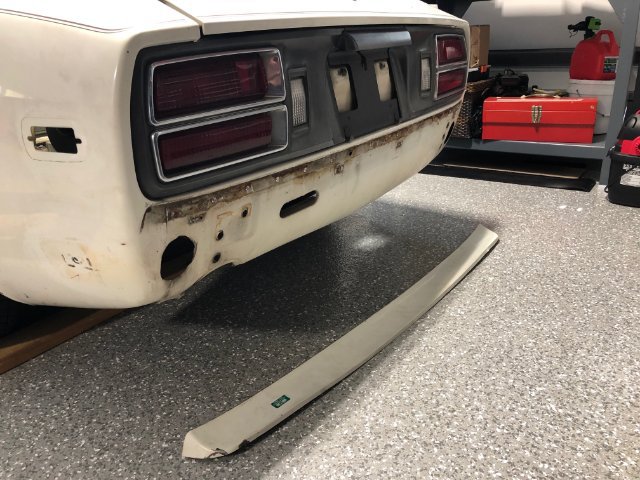
I don't have a whole lot to show at this time until the wheels arrive (later June) and the chassis (hopefully September). I finally removed the ugly rear bumper gap cover by drilling out the spot welds. I managed to only completely perforate the body once in the process. Steering rack simulator linkage below. Tubes cut to length, I just need to prep and weld in the threaded tube ends. This will be my first real welding project with my Miller 200DX which I bought 9 years ago (for the Datsun). I am a novice welder, having TIG welded some tubing back in the 1994 timeframe, and only about 5 minutes of TIG welding since that time with my inverter TIG. The outer links are 7/8" OD tubing, chosen to match the link tubes O.D. that are coming from AME, because one of the other things I need to check is that at full track travel, they don't interfere with the front sway bar links. AME already drop shipped the Wilwood front brake kit (12.88" rotors, aluminum hubs, 6 piston calipers) at my request, so that I could get the hubs ready to mount on the spindles when I have the chassis in my driveway. The chassis comes assembled in the crate. I have to be able to mount the wheels to roll it into my garage. No forklift at home! Wilwood BP-10 pads included. Anyone know if they are any good or not?
-
AME complete chassis '77 280Z
lifeprojectZ replied to lifeprojectZ's topic in S30 Series - 240z, 260z, 280z
Thank you. After 21 years of sitting on it, I finally decided to make a (major) move. Now there is no looking back. I am committed and need to have this on the road within a few years. -
AME complete chassis '77 280Z
lifeprojectZ replied to lifeprojectZ's topic in S30 Series - 240z, 260z, 280z
The (incomplete) plan at this time is to cut out and disgard the floor pans and most of the deck area inside the hatch. Will also remove the rear strut towers since I won't be needing those with the new IRS. See in the attached photo how I will route the 2 x 4" rect tubing along the inside of the rocker panels. I will drill out all of the spot welds in the vertical lip below the rocker panel, and plug weld those holes directly to the tubing. This is the only part of the body-to-frame connection I am sure of at this time. The rest of the areas I will have to figure out as I go and will probably be bending a lot of sheet / plate metal in the interface so that my welds are either lap welds or plug welds.
-
AME complete chassis '77 280Z
lifeprojectZ replied to lifeprojectZ's topic in S30 Series - 240z, 260z, 280z
The wheels are supposed to arrive week of June 13th. Specs in first post. A direct contact at Forgeline has been very helpful. Can't wait to see them, and will post pictures and details of how I decided on the sizing and spacing for anyone who might be interested. I am nervous as hell about the dealer mounting the tires on them and not scratching them in the process. I am also (slowly) working on fabricating a steering rack "simulator" which will allow me to do several things: 1) Tie together the steering arms of the spindles when I uncrate the chassis in my driveway this fall so that I can actually steer the thing into my garage. 2) Locate it in the (baseline) position specified by Art Morrison so I can check Ackermann steering geometry and bump steer for myself. 3) Move it to other locations (namely, down and rearward) to check the same and try to improve clearance with the engine. 4) Adjust (reduce) pivot-to-pivot distance if necessary to achieve the above. All of this so that I can be sure before I order the custom rack from Woodward. -
AME complete chassis '77 280Z
lifeprojectZ replied to lifeprojectZ's topic in S30 Series - 240z, 260z, 280z
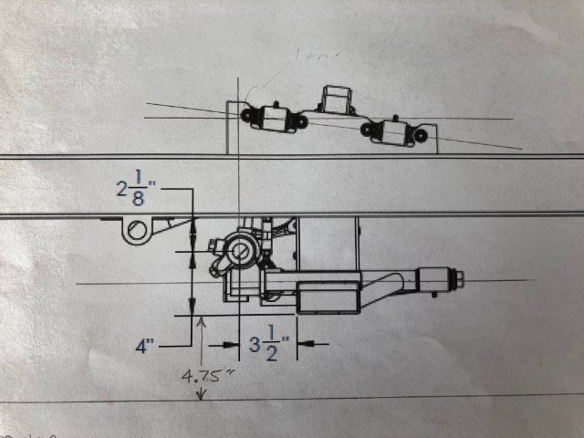
I now believe this was more of an issue of my expectations as a mechanical engineer who has developed and/or led many designs over the years with companies having varying levels of design / engineering talent. I am accustomed to receiving and studying dimensioned prints and the back and forth that design work entails. So when I heard I would be receiving prints, my expectations were in line with my experience. I always like having more dimensions vs. less, but in the end they have provided what I needed. I also don't like communicating with someone's engineering department through a salesman, and usually don't, but I understand the reason for their business configuration. Through later conversations, I came to realize that most of their customers order their pre-designed frames, and just pick options (e.g. brakes, etc.). So there is really no custom engineering to those. Then, of the few who custom spec a chassis, they rely heavily on faith in Art Morrison's reputation. I have gotten burnt too many times in life doing that with contractors of all types, and I explained it that way to the salesman at AME about a week ago when he, very politely, informed me that I was the first customer to ask about ackermann, and no customers ever go into anywhere near as much detail as I have. Of course I thought that was odd because I don't feel I have gotten into much detail at all! Anyway, speaking with their company president (won't mention names here, you can see his name in their catalog), I believe they do have very good engineering talent on board, and have designed their products very well. They also have a business to run, and I respect that and understand the impact of custom fabrications in a streamlined manufacturing environment, which is what they have developed. From what I can tell, they build about 40-50 chassis / month. Today I spoke again with AME to finalize the designs and confirm that I will make my own bracket for the steering rack (which Tony Woodward convinced me to do). When I finally understood the design of the bracket AME had proposed, it was an easy decision. Tony has been a wealth of knowledge, as anyone who has spoken with him knows. Throughout the conversations I felt like I was right on the limit of his patience, but fortunately I averted any disasters. I am waiting on some additional info from AME now before I order the rack. They gave me the pivot-to-pivot distance, but I would like to see this for myself on an overlay with the suspension pivot points. An exercise made a little more difficult because the upper arm is on an inclined plane. When I receive (or not receive) the info I requested, I will post a diagram of a few design elements. -
ANOTHER Datsun Z/LS3/T56 Swap Thread
lifeprojectZ replied to Ironhead's topic in S30 Series - 240z, 260z, 280z
Sorry if I missed this somewhere in the preceding 28 pages, but I don't recall your assessment of the 525HP other than your initial impression. Now that you have driven the car a bit, do you think you would ever want or could use more HP? Is first gear even usable with the rear diff ratio you choose (above 4:1 right?) Also, I saw your dual master cylinders and the balance bar set-up, but what size rotors front / rear and caliper piston area do you have front vs. rear? Considering all this, what do you think your current braking torque balance is front / rear after your tuning and are you happy with it? Did you you ever weigh your car to see what the weight distribution came out to be? These are the things that keep me up at night... -
AME complete chassis '77 280Z
lifeprojectZ replied to lifeprojectZ's topic in S30 Series - 240z, 260z, 280z
If you look closely at the OE S30 fender lip, that max body width of ~63.5" is only captured at a very short section slightly toward the front of wheel centerline. Then the rest of the lip curves back inboard fore/aft. The more I look at it, the more I dislike it. Honestly the thought of adding flares has me stressed because I am not looking forward to body work of any type, and want to farm this out as much as possible after I have done the major structural / mechanical work. So I try not to think about them too much for now, but I am sure that it will be easier overall the smaller flare that will be needed. -
AME complete chassis '77 280Z
lifeprojectZ replied to lifeprojectZ's topic in S30 Series - 240z, 260z, 280z
Agree completely. I believe it may be a matter of cost. They have some good endorsements backing their IRS which was a draw for me. On turns, the inner wheel toes in and outer toes out due to the multi-link setup. Supposed to help. Yeah I am hoping not to make any major mistakes, but I am sure there will be at least small ones made and money spent on education, unexpectedly. For me the wheels are one shot. I will live with what I get. AME claims my choice of fronts will provide more than adequate turn without touching, and they even encouraged me to bring them inboard more. I wanted to keep the track width the same as OE and in fact that is what I have done considering the positive offset of 0.5" counters the increase in hub track of 0.5". The result of using the 18 x 9 wheel is that the tires will fill out completely to the OE fender lip and perhaps a tiny bit beyond. On the rear it is a different story. I was/ am mostly concerned about fitting a 14 x 9" Borla muffler behind the tire, between the rear chassis member and the quarter panel. Pretty tight in there. Exhaust routing will require mitre cuts/welds, and I may have to tear into the muffler to create a custom entry from the side (I hope not). But I did not want tires sticking way out the sides for my project. Just don't like the looks, and I am not convinced it is necessary to improve handling. So I think I finally convinced myself to tuck them in so that outside-to-outside of the tires will be the same front/ rear. But the 295's on rear will of course go in deeper. -
AME complete chassis '77 280Z
lifeprojectZ replied to lifeprojectZ's topic in S30 Series - 240z, 260z, 280z
Quick update. Chassis and Steering: I received the design for my chassis this week and have had a lot of back and forth with AME trying to pry out details to better evaluate it. Not as forthcoming or as detailed as I was expecting, but slowly and surely have managed to get answers. I will sign the print and turn it in next week so they can put it in line for build. If they will allow me, I will post the diagrams here in the future so all can see for what it might be worth. Today I called Woodward and spoke with Tony, as a few of you have who bought a rack from him. He convinced me to locate / weld the rack bracket on myself and not leave this to AME. The more I look at it, the more I agree, as I see the need for the rack to be set back to improve ackermann as much as possible and also get a stiffer linkage in hard turns. When I start asking really detailed questions to AME, I get some resistance and the comment that I am their first customer ever to ask about ackermann geometry and other such details, so I can only imagine if I were to ask for a fully dimensioned suspension diagram. Wheels: I decided to go with Forgeline G3A wheels (https://forgeline.com/wheel/ga3). 18 x 9 on front with 5.5" backspacing, with 255/35 tires, and 18 x 10.5 on the rear with 7" backspacing, with 295/30 tires. Both tires will be square with the tire manufacturer's design wheel widths for each, and both have diameter of 25". Those factors weighed heavy in my decision, as I didn't want to get much larger in diameter. The AME front and rear suspension has hub track width of 55.5" which is 1" wider than the OE Datsun. Tire bulge side to side will be about 64.5", so I will need small flares, and am planning on welding on metal ones and blending in. Total width of the OE Datsun fender lips is somewhere in the 63.5" range by my measurements. For a while there I was thinking of using 6.5" BS on the rear, but then the tires would have bulged out 1/2" more on each side than the fronts. Probably not noticeable from a visible standpoint, but I am hoping that tucking them in more will counter the car wanting to "plow" as the president of AME said he thought it would when I spoke with him the other day. Plan is to order the wheels and tires this month before prices jump. Got a good price quote from Hawks Motorsports locally, significantly below the retail price on the Forgeline website. Would love to hear any thoughts / experiences others have on wheel tire combos, wider track in rear vs front, and what effect you saw on the track. Brakes: AME sent me the Wilwood front brake kit. I will post some photos later. Includes 12.88" rotors w/ aluminum hats, aluminum hubs, and FNSLR6 calipers, etc. -
ANOTHER Datsun Z/LS3/T56 Swap Thread
lifeprojectZ replied to Ironhead's topic in S30 Series - 240z, 260z, 280z
That looks great. Maybe someone will develop a retrofit kit with adjustable assist. Maybe not due to liability. Looks like it takes up about as much space forward of the firewall as a vacuum booster though. -
AME complete chassis '77 280Z
lifeprojectZ replied to lifeprojectZ's topic in S30 Series - 240z, 260z, 280z
The chassis I ordered three weeks ago is their "Max G" shown on page 6 of the AME 2022 catalog, except that I ordered the compact IRS instead of straight axle housing shown. They have spec sheets where you can specify a certain number of dimensions to tailor the frame to your specific needs, and that is what I did. They have designed frames already for a lot of cars, but not the Datsun Z. And yes it is a fully aligned and welded assembly, so my task is to cut out what I don't need / want from the Datsun unibody and mount the rest to the AME chassis. Imagine just the outer shell of the body but including the firewall, trans tunnel, and rocker panels. That is about all I will use. There is a "but". I found that AME was not really willing to customize the chassis as much as I wanted them to, because even for the Max G customizable chassis, they still use a jig and follow certain standard designs and layouts. So they will only let you do so much before adding on tons of additional money for custom fab work. For this reason, I decided to make a compromise in the foot well area and will have to cut out and reinforce a section of the front frame rail which passes through the firewall straight back into the foot well that would otherwise inhibit movement of my right foot to reach over to the brake pedal. After sending them several of my design ideas and being met with resistance to doing anything different, I decided the best approach was to let them build the chassis using their standard layout, and then I will modify what I need to in that one area. After studying this quite a bit, I don't think my modification will compromise the structural integrity to any significant degree, nor will it be too technically complicated for me to pull off with my skill level and tools on hand. I'll provide more detail about this when I receive the chassis later this year. I also decided to build a cage. For safety, extra torsional rigidity, compliance with NHRA/SCCA rules, and just all around coolness if none of the rest matters. But my cage will be minimalist on the inside, with extensions reaching out to the front rails. I see many guys going far beyond what the rules require for a cage and what I think benefits them, and I don't plan on doing that. I still want to keep weight to a minimum, so I will be removing all of the Datsun underbody reinforcements, strut towers etc. to lighten as much as I can. At this time I only have a solid plan for how to weld the rocker panels to the 2 x 4 frame. I am not sure how I will attach the other sheet metal edges to the frame, but I am sure that I will figure this out one step at a time. I am a novice TIG welder, but I have a good machine so I am sure that with some practice I will be able to do all of the welding necessary. -
AME complete chassis '77 280Z
lifeprojectZ replied to lifeprojectZ's topic in S30 Series - 240z, 260z, 280z
Someone interested in the Ford 8.8 IRS parts I just posted for sale in the Parts for Sale section asked me to tell more of my story of how I arrived at those parts to begin with, so I thought I would take a step back and provide some background here in the event that it may help or interest others. Back around the time I bought my '77 280Z (2001), I was planning a lot of the common modifications being discussed on hybridZ at that time, including sectioned struts with coil-overs from Ground Control, 300ZXT CV shaft conversion, 5-lug hub conversion, and a Chevy V8 (that alone is a story in itself for another day). All of the reading I had done to that point in time led me to believe that the OE R200 differential would be sufficiently strong for a 400-500 HP V8 because of the light car weight and the belief that I would never run slicks (I still don't think I will), so the diff would have a relatively low stress life. I was planning on a torque biasing differential like Quaife, but other than that I was satisfied with the 200mm ring gear, instead focusing my mods on converting to CV shafts and eliminating the crappy U joints from the half shafts. Fast forward through moving to South America in 2003 and returning to the US in 2010, I pulled the Z out of storage and started working on it again. I started buying up core CV shafts from the 300ZXT, and bought the billet steel 5-lug stub shafts from Modern Motorsports (no longer in business I believe) because I wanted to run 5 lug wheels. I tuned in again to hybridZ, and started to pick up on a new idea of using the Ford IRS 8.8 aluminum diff housing together with the 2003-2004 Mustang Cobra CV shafts with 31 splines. This differential housing can be found in several Ford models including the 2001-2004 Mustang Cobra, Ford Thunderbird, Lincoln Mark VIII, etc. but only a few of these models use the dual mount on the front of the diff housing, so of course I had to get one of those, and the Lincoln Mark VIII had it. Someone found that the rear differential cover from a Ford Explorer of the same time period had extended side mounts, so that also seemed like a good idea to me to stabilize the differential housing mounting (still seems like a good idea to me, we don't want that thing moving around). What a great way to save weight, improve gear ratio options, and have bullet proof rear axle shafts. So like the junk yard addict (probably a poor description, but I mean one who loves to combine OE parts from different car models into one thereby making it much better!) that I was, I started accumulating those parts. My plan was to buy original (NEW) Cobra CV shafts and then send them out to get shortened. Reman shafts were not available at that time. Only used and new, so I bought new. I planned on using the Ford hubs (5 x 4.5 bolt circle) and hub bearings, and my custom fab work would be limited to the rear Z strut / knuckle assembly, which would need to house the bearing for the hub and keep all that junk from ejecting while driving. Really not a difficult design project, the trick is to design it such that it can be fabricated easily and at the lowest possible cost, so this requires several components which would be bolted together, unless you have a milling machine at your personal disposal. Try to keep welding to a minimum or eliminate altogether to avoid distorting parts and introducing residual stresses, unless you plan to stress relieve your parts. Of course the strut tube must be located properly on the knuckle, and you need to consider shortening that as well for coil-overs and lower ride height. I was planning to use the same Tokico BZ3099 struts I have for sale now in the rear as in the front, because I was going to raise the strut tube up higher on the knuckle, so you would need the shorter strut. .....So I got a scrap IRS aluminum knuckle from a Thunderbird (same as the Mustang), and started taking measurements and planning out the design. It was at about that time (2015) that I realized the best plan for my job and my family was to pick up immediately and move to Barranquilla, Colombia, so I did that and stayed there for 4 years while the Z slept in storage again. 2019 and back living in the USA, I decided to say screw it with all of the custom fabrication for the rear end. If I am ever going to finish my project and enjoy it, I needed a big jump start, and I don't really want to be disappointed with the handling after spending many $1000's throwing aftermarket parts at it. I remembered discussions with one senior member (still on hybridz) back 20 years ago who raced his V8 Z and told me that the rear suspension was limited design-wise and needed to be replaced with something better to get to the next level. Through Youtube and some other sources, I became aware of other Z enthusiasts who have gone to extremes to modify the rear Z suspension and even created a fancy new suspension specifically for the Z car with shocks inside the rear hatch area, but after looking closely at these designs, they looked very flawed to me. A double-articulated swing arm seems like a very bad idea to me. I am a mechanical engineer, and I did study mechanical linkages and automotive suspension design. Doesn't make me an expert by any stretch of the imagination, but it helps me to consider concepts and ideas with a better understanding of the potential pitfalls. I started looking at Art Morrison and found they offered a custom chassis built to customer specifications. Price tag is very high, and it took me a couple of years to finally come to terms with it. But I don't see myself ever buying a sports car, and the fun is in building something yourself, getting to the end result. I could definitely design a suspension. But in reality, it would be a beginner level suspension, not a race proven and tuned one, as the AME suspensions are. And it would take me forever to build. I don't have a chassis jig. So I decided to take the leap finally, and have settled with slicing apart the 280Z body and welding (a large piece of) it to a pre-made chassis to my specs. A chassis already aligned and set up with a race proven front / rear suspension. So about a year ago I sold off the billet stub axles and collection of 300ZXT CV shafts. Now I am putting up for sale the rest of the (Ford IRS) parts and some other stuff I accumulated which I will no longer use. For someone else who has the ambition, resources, and the ability to follow through with their adaptation, they are quality parts. -
ANOTHER Datsun Z/LS3/T56 Swap Thread
lifeprojectZ replied to Ironhead's topic in S30 Series - 240z, 260z, 280z
Thank you! That is a wealth of information. If you don't mind, how much ground clearance do you run with the Holley 302-2 pan? I am wondering where my LS will end up in the AME chassis. I want it as low as possible of course but I don't think I would want much less than 4" ground clearance with the pan. Won't know for sure until I get it in there and start playing around. -
ANOTHER Datsun Z/LS3/T56 Swap Thread
lifeprojectZ replied to Ironhead's topic in S30 Series - 240z, 260z, 280z
Did you happen to use a sound deadening headliner, or is it sprayed metal? I noticed a huge difference in inside noise of my '81 Buick (full of original carpeting, sound deadening) with 350 crate engine, 3" dual exhaust when I got the bright idea to rip out the sagging headliner and paint the metal. At that time I enjoyed the sound (25 years ago) but today I wouldn't. I appreciate your comments on the noise. Will go extra heavy on the sound deadening! The AME sales guy talked me out of a 3" dual exhaust for my Z for the reason of being too noisy. I had never thought about the exhaust size making a difference in noise transmission to the interior, but he has seen/ heard a lot more than I have. My biggest obstacle to a 2.5" dual exhaust is mental and too much past reading about exhaust sizing needed to extract every last HP from the engine. I doubt I'll be spending much time above 6000RPM with the LS376/480, and the lower RPM torque will probably be a closer friend. Originality? That is extremely important to me. In fact I bought factory original replacement body vent emblems, and plan on installing them........