
bjhines
-
Posts
1963 -
Joined
-
Last visited
-
Days Won
4
Content Type
Profiles
Forums
Blogs
Events
Gallery
Downloads
Store
Posts posted by bjhines
-
-
Modern aerodynamics. You have to consider that our small frontal area S30s are horrible when compared to much larger modern cars.
-
you might check this thread.http://forums.hybridz.org/index.php/topic/61465-woodward-steering-joint-group-buy/ Most of the lower shafts are worn out and the stock shaft is too springy.
-
I have a highly modified suspension, set up for track use and sticky tires. The car is NOT slammed low. I have lots of caster and neg camber. I have cut the fenders and installed regular ZG flares. I had to cut the airdam/valence. I can only run 245,40,17 tires with those wheels. I have purchased wider flares and will see what tires will fit after that.
-
You can find a variety of distributors for silicone coated fiberglass sleeving. If you shop the surplus suppliers you can get a great deal. http://www.skycraftsurplus.com/hightemperaturetubing.aspx
...
-
I know that you can have 3 holes, 5 holes, or 6 holes on 2 different spacings on the steering wheel side.
The Datsun tapered spline adapter is not uncommon. The major steering wheel manufacturers have them to fit their wheels.
Many folks have welded adapters onto their column shaft for quick release hubs.
The wheel (usually) needs to be smaller dia., lower, and closer to the driver when seated in a race seat and harness.
-
It is generally a good idea to use the same size feed and return lines, especially when using overkill pumps that can provide race car peak flow but sit at stoplights some days.
-
I have fixed several S30 fuel lines over the years due to rust through. The battery tray drips onto the lines there and causes exterior rust through. The lines get bent and snap at the rear where the tank hoses attach. The factory 280Z tank had a problem with the pickup line breaking off in the tank. Partial breakage inside the tank will allow air into the lines. There are enough problems with an old fuel system to consider replacing everything fuel related.
Your motor choice would probably run fine with 3/8" lines and a high pressure pump. There are several discussions about fuel pressure regulation and various routing ideas, pros, and cons. Going with a more sophisticated return regulator system may require relocation/replacement of existing lines anyway.
-
wooo hooo... pics please, even if its messy.
-
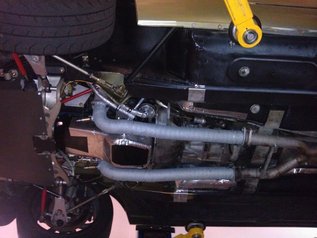
Helmholtz resonator. It knocks one narrow band of obnoxious sound down to a reasonable level while still allowing an aggressive exhaust sound. It is the fix for the interior DRONE.
-
I went to the effort to plumb a cooler. I added a return to the top oil channel and tapped the drain plug. I installed a CHT temp gauge that goes almost to 400f. I have a NEW R200 with the NISMO LOM59 CLSD, V8 ROAD RACE engine. Track sessions in summer reach 350f without the pump running, it stays closer to 200f with the pump on.
I draw from the drain plug, pass thru a spin on remote filter, thru a small Setrab cooler, thru the pump and return to the top front channel, all AN-6 hoses. I use standard weight Redline synthetic gear oil.
Now that the diff has some break-in time, it appears to generate less heat. I melted the mushroom vent on one in a different car, so I know they get plenty hot on track. 400+f
-
EGR only works at part throttle. It will not "IMPROVE" performance to remove it because it only affects part throttle operation. People removed EGR when it was malfunctioning or when the carby was retuned or replaced with a "performance" model. Some people naturally assumed that EGR/.emissions systems must be bad because the American auto industry made a disastrous mess of EPA conformance in the 1970s and 1980s. Folks have made all sorts of associations with emissions being BAD for performance because of the total crap US car-makers tried to sell us for decades. How much power did the 1982 corvette have?...i think less than an modern L4 with 1/4 the displacement. Those anemic 1980s V8s are a fricking JOKE!!! No wonder folks have a bad memory of emissions systems.
Tony... The wood smoke truck ran on the volatile, combustible fumes that wood gives off when "cooked" in an oxygen free tank. Those fumes can replace gasoline and have been used in remote locations as a frustrating and dirty fuel source to run engines designed for spark ignition operation. You have to regularly shut down to clean out the wood remains and clean the pipes of condensates from the wide range of stuff that comes from cooking wood. The wood chips used must be bone dry or the steam will form varnish in the plumbing.
.
-
Odyssey PC-680 to start the V8. No problems for 2 years.
-
Well... Eliminating a single "peak" in the response is EXACTLY what fixes the cruising DRONE. Helmholtz pipes are the remedy and will allow an aggressive sounding muffler without the interior drone.
-
Hehehe... Gear oil cushions the parts and makes the slop harder to detect. Lack of oil will make the slop more obvious and clicking sounds louder.
-
LOL...
I thought this was HybridZ.... The whole point of this site is swapping motors into Z cars because the L series is too wimpy and expensive to build to relatively wimpy power levels. The OSG head is a waste of aluminum.
-
I have seen many modern exhaust systems with Helmholtz resonators near the Mufflers. This is a simple "dead-end" tube of a certain length, tee-ed into the pipe right before the muffler. They are usually around 20"-30" long and the same dia. as the exhaust tubing. They act like speaker tuning ports and use the same descriptive name. Speakers use them to limit the motion of the speaker cone and smooth frequency response. They work the same way in exhaust systems but are used to minimize the pulses entering the muffler and the energy is blocked from escaping the exhaust system with a cap on the end of the pipe.
Here.. check out a discussion here.
http://www.performan...hread.php?t=144
and a paper on the subject of mufflers in general.
http://www.paraglidingteam.nl/PPGTechnics/sound%20and%20noise/Mufflers/1155795969.pdf
...
-
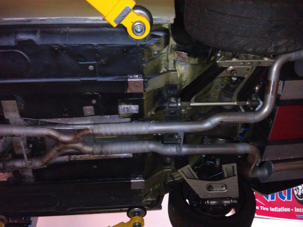
2.5" dia. That is a JTR install with their entire kit.
-
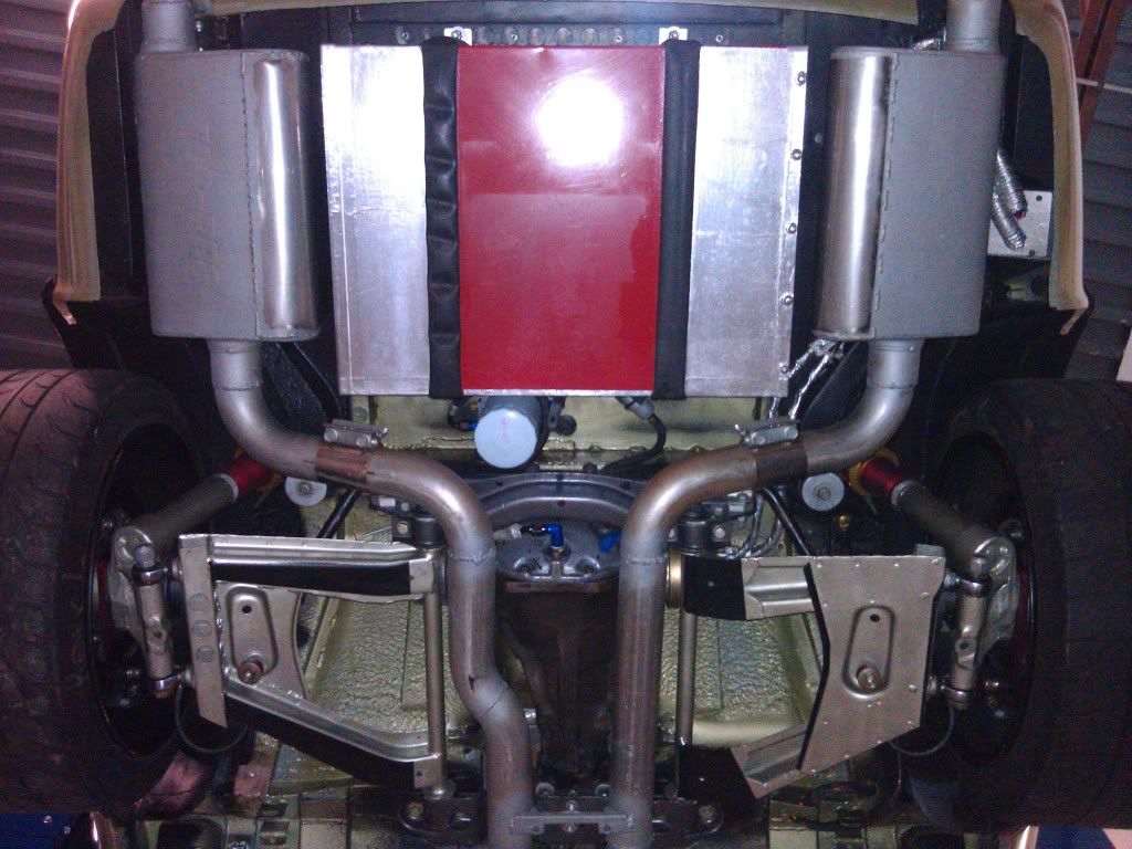
Mine does not drone and it has relatively free flowing mufflers. The exhaust is loud... but there is no resonating drone.
Here is a testing video from it's first runs. http://forums.hybridz.org/index.php/topic/96660-skidpad-testing-video/page__p__908141?do=findComment&comment=908141

...
-
-
Well... I tried several combinations to arrive at Hawk Blue on the fronts, and hawk black at the rear.
My current track car has an adjustable brake bias bar in the pedal box with individual master cylinders to allow for changes at the track.
A lot of things can change due to suspension related dynamics, so keep that in mind. Just putting Hoosier slicks on it can completely change the brake bias needs.
-
I appreciate the interest, but we need some engineering math to deal with the issues that come up with cooling modified engines and cooling systems.
Considering the discussions regarding,...
1. Radiator size and design of the tubes, fins and tanks.
2. radiator baffles(covering part of the radiator). Cooling shock/temperature fluctuations due to over-cooling water in the radiator.
3. Airflow through the front end, cowl induction scoops, and additional inter-coolers and oil-coolers that have caused problems for many people on this forum.
4. water pump size, operating RPMs, and electric WP control systems.
5. coolant bypass in the head, block, and thermostat housing.
6. mechanical and electric cooling fans and control systems.
There is a small book's worth of theory, part number tables, historical data, and electrical diagrams just to cover DATSUN 240Zs.
-
That's another one I might try to find cheap to test with.
-
So... The pump pulls excessive current at +4"hg vacuum. I should limit it's operation to below 3" vac or so.
1. A 3" vac switch hooked into the crankcase or recovery canister should do the trick. The pump would cut off when crankcase vac approaches 3" and we are good. PCV valve should do the trick at idle and part throttle.
2. A 10" vac switch in the intake would cut the pump off whenever the intake vac is greater than 10". This would indirectly control the pump when PCV valve is capable of providing flow. The pump would only turn on when the throttle is mid to WOT.
3. A micro switch on the throttle would cut the pump on at mid to WOT. This would ensure that the pump only works when the PCV cannot. This is another indirect approach but it would work.
4. A relief valve that would open to atmosphere to allow free airflow for the pump under high crankcase vac conditions. The LS1 A.I.R. system came with a large 5/8" port tee that opens when 10" vac is applied to the diaphragm port. I could indirectly plumb this to intake vacuum to open up the port on the tee when PCV can do the work. This would allow me to run the pump all the time and simply relieve the load on the pump.
5. I could combine several switches into a logic controller that could do many things under different conditions.
I would like any help finding a vacuum switch for this purpose. Does anyone know what to look up when searching for an automotive Hobbs switch that is not $100 or more?
-
see there.... Look at you... Got this thingy going all ready and I am just beginning to figure it out. It appears that mine already had the foam removed. I would mount the pump assy with the motor UP. You have it DOWN and oil will collect in the rubber bulb that encloses the motor. We may even need a drain in the plastic cover with a one way nipple to drain liquids when the pump is off.
I am looking for vacuum switches. I can't seem to find many automotive versions. I have found some industrial and refrigeration related parts, but they are very expensive(>$100).
So... The pump pulls excessive current at +4"hg vacuum. I should limit it's operation to below 3" vac or so.
1. A 3" vac switch hooked into the crankcase or recovery canister should do the trick. The pump would cut off when crankcase vac approaches 3" and we are good. PCV valve should do the trick at idle and part throttle.
2. A 10" vac switch in the intake would cut the pump off whenever the intake vac is greater than 10". This would indirectly control the pump when PCV valve is capable of providing flow. The pump would only turn on when the throttle is mid to WOT.
3. A micro switch on the throttle would cut the pump on at mid to WOT. This would ensure that the pump only works when the PCV cannot. This is another indirect approach but it would work.
4. A relief valve that would open to atmosphere to allow free airflow for the pump under high crankcase vac conditions. The LS1 A.I.R. system came with a large 5/8" port tee that opens when 10" vac is applied to the diaphragm port. I could plumb this to intake vacuum to open up the port on the tee when PCV can do the work. This would allow me to run the pump all the time and simply relieve the load on the pump.
5. I could combine several switches into a logic controller that could do many things under different conditions.
hmmmmmm.....
Replica 240z
in S30 Series - 240z, 260z, 280z
Posted
Ohh yeaa.... Post em up.
I know we all have questions, even if we are dreaming.
What does it weigh?
what kind of reinforcements are inside.
Post your prices and estimate shipping to east and west coast US for the smaller parts.