

goodoldjam
-
Posts
199 -
Joined
-
Last visited
Content Type
Profiles
Forums
Blogs
Events
Gallery
Downloads
Store
Posts posted by goodoldjam
-
-
well I love me some stickers.
How about, the best powerslide on a dirt road, scandinavian flick style
 After-all I do live in montana.
or set up a video camera of your car in a parking lot, and first one to get broken into wins.(kidding)
not gonna lie, I feel the burn out one is the best idea.
Burnout is a good idea...Is it required to have 2 wheels spinning?
-
The poor 280zx was the shell I sent to the crusher and every other 280zx i see in the yards waiting to be crushed.
I can't hate on this guy for putting the car to use.
-
Looks awesome. Whered you get the materials?
Here's where i got the bends http://www.mandrel-bends.com/catalog/.
I did spend more then I thought. $38 for the 3 45deg bends.
I bought the straight pipe from NAPA, I got 7 feet of straight for $32.
The 3 bolt universal flanges are cheap. Ebay V-band kits are not bad, though the clamps are cheaply made.
-
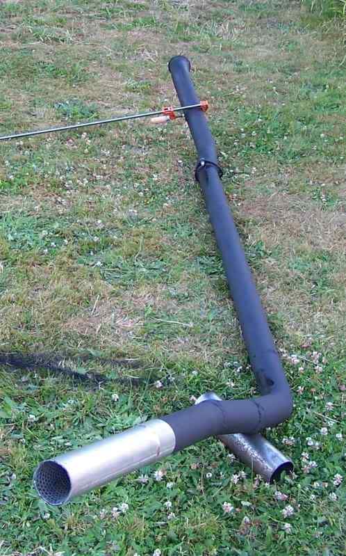
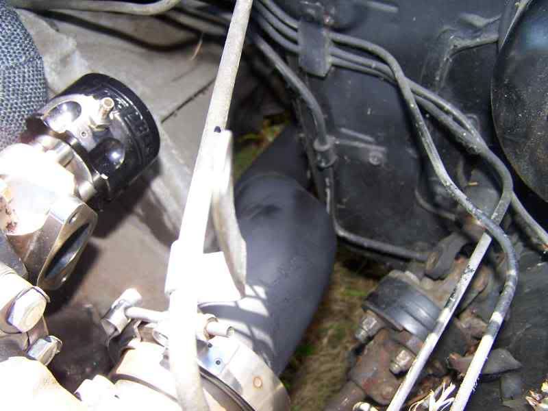
This is close to the actual orientation of the exhaust.
DP to exhaust.
Not quite just 3 45s, had to make some slight adjustments to clear the tank.
-
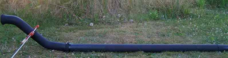
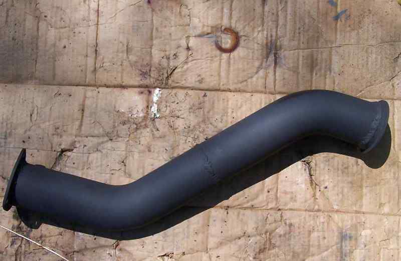
Wasn't sure if this was going to work out, but test fitting is looking good. So finished the DP with 2 45deg and fitted a straight pipe. Then the straight to a 45 and I'm going to leave it kinked out the back...Hopefully, I'm trying to get that fitted right now.
Finished DP.
Better picture of how it is routed between the fire wall and tranny, It's not touching either.
Biggest pain is going to be making a screamer pipe, the wastegate outlet
flange is pointing towards the DP.
-
How mush do you want spend?
You can check out the pick in pulls but they're not even close to as cheap as they use to be. Now they charge a core price also. http://www.picknpull.com
Also there is a guy in Gladstone with Z parts, you maybe able to get a deal from him. When i went he had about 6 Z/ZX's and quite a few diffs already out.
His name is John Walker 503-655-2256.
-
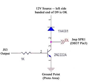
The V3.0 flyback circuit is for the injectors. Using the diode is a good idea.
Now I'm thinking I need to do it. So The Fuel pump relay is going to need a diode then. So does the relay board have diodes in place?
Edit: Answered my own question nevermind. I see on a one of your DIY writeups that you added a diode for IAC.
-
I think you shouldn't have to worry about it, V3 boards had built in flyback circuits. Learned a bit from talking with Jacob about his fan circuit. Basically only time you need to add one is when you add a new transistor circuit. If you did need to add some, your transistor would have already failed.
This is a very cool read. http://www.autoshop101.com/forms/hweb2.pdf
-
Cool man glad to hear it, ignore the above diagram no point in testing like that if you have it working.
-
The resistor would show 1k ohms resistance if you were to check it. I believe checking the diode you just check resistance and it should be open one way. Very high resistance in one direction and almost none the other.
Maybe you need to run a wire from your output to a relay and power the other side. Then test it's operation.
Check if 30 and 87 have continuity when on. I keep getting the feeling that going directly from a power source and and to the output isn't exactly the right way to test it's operation. If that doesn't work then you know for sure that something is wrong. From the looks of it you built the circuit exactly right.
-
I forgot about the oil inlet and return gaskets on the turbo. Those aren't really necessary if you don't remove the flanges. You can just remove the dump tube hose and the banjo bolt.
You may want to pick up some new washers for the banjo fitting.
-
So if you were to test from the none banded side of the diode, I'm wondering if you would see voltage while off.
-
The turbo has metal gaskets you can reuse them.
-
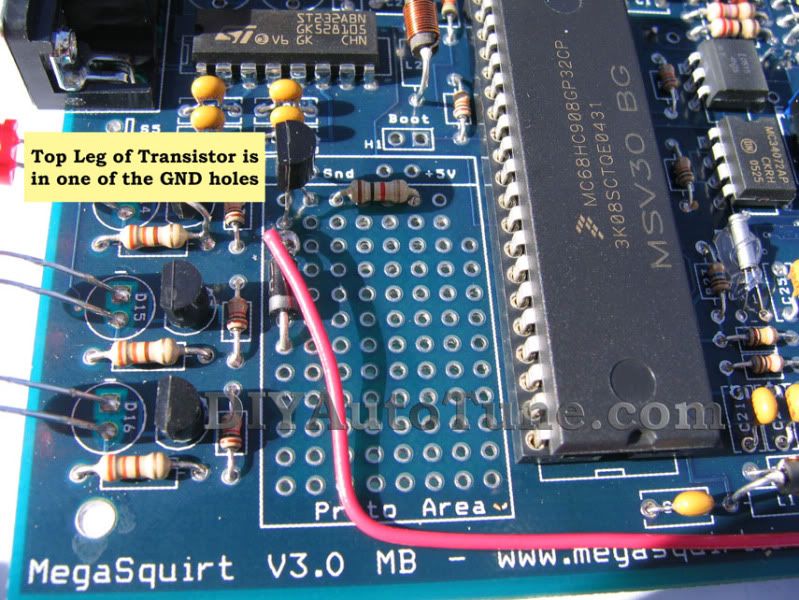
So it's looking like the transistor is working. Was the diode between the power source and 29? Maybe that is why your seeing voltage when you shouldn't.
Actually I'm lost to why your seeing 12v when it's off, if there is no continuity between the collector and emitter then why would that be happening?
Is this what your proto area looks like?
-
Driveline services in Portland Shortened and replaced my U joints for a little over a $100. http://www.driveshafts.com/
To have one made would cost a bit but you should talk to these guys.
They actually had to replace the flanges where the bearing caps sit in, because they were messed up. So basically I gave them a metal tube.
-
Yeah no voltage when off, 12v on. So your getting constant ground, when it's on something is taking voltage. Check resistance between 29 and a ground. If it's showing continuity while off then something is wrong. When on it shouldn't be showing voltage if you take your leads and go to ground, or very little voltage.
-
Looking at these two diagrams:
http://www.diyautotune.com/tech_articles/common_megasquirt_modifications.htm#Add_Output_v3
http://msextra.com/doc/ms2extra/MS2-Extra_Hardware.htm#outputs
Essentially, the top diagram looks like it is only manipulating power (or ground, not sure whether its grounding or sending 12v+) to the coil positive (or negative). But, the bottom one is showing that it wants to be attached to both sides of the coil, hence my last drawing routing two separate leads out to the relay board. Which one is better?
The second diagram isn't saying to use megasquirt for power. It just wants you to have a diode between the ground coming from megasquirt and the power source. You could take the power directly from the battery and say run pin 25 IAC A1 to the negative of the relay. I believe they are both the same diagrams, second is just a generic example. Purpose of the diode I believe is to protect megasquirt from seeing a huge voltage spike when the relay closes, I'm probably totally wrong on that though.
-
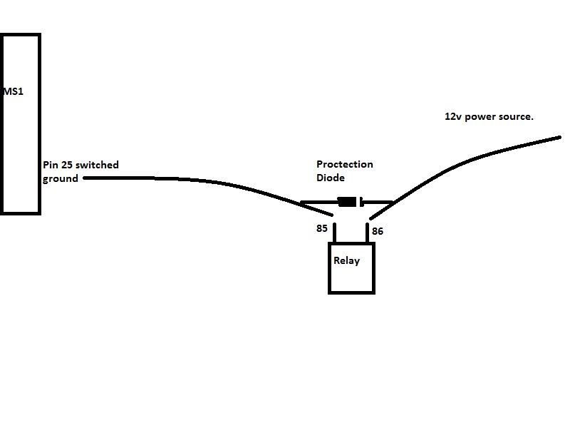
Lets look at it how you had it before during your testing.
So you had basically zero volts and continuity when it switched on? So you had a working switched ground from megasquirt. So that was working. Now you need that to make it to the negative side of the relays coil, 12v source should come from? Lets leave out the relay board and imagine connecting directly to a relay. All we need to get the relay working is 12v for the other terminal.
Like this,
This maybe helpful on how to get power to a relay. http://www.msextra.com/forums/viewtopic.php?f=101&t=35256
So relayboard #7 is pin 25 your ground and #8 is the 12v source, that's what I'm gathering from this.
Probably should wait for Matt to verify it though.
-
Hmm...interesting. If this is true, then my relay is wired wrong. I have it wired so that the Megasquirt would be providing 12v.
Should I rewire the relay AND turn the diode back around?
I'm thinking you probably should. You can test it by hooking up pin 25 to 85 terminal on a removed relay and feeding power to 86. Then when it switches check continuity between 30 and 87, if that is working properly then your ready to go. Which from your testing should work, that was before you reversed it.
You maybe could test the connectors on the relay board, you need a negative and a positive on 85 and 86, if you have 2 12v sources that would explain it.
-
This is the diagram that gets me. C to terminal 85 on the relay which is ground, 86 being your switched. Comparing with the other diagrams IAC1A shouldn't be seeing 12v. I'm thinking that the .005 volts was what you wanted to see , as long as it was completing the circuit when it was suppose to. I do think it was working like it was supposed to.
-
That's what I'm thinking maybe off, I don't think your trying to feed 12v to the relay. The 12v source is switched or constant. Pin25 should be grounding the relay to activate it, it seemed to be doing so in your test. Again I maybe totally off base.
If you did hook pin 25 during that test to the negative on a relay and a 12v source to the positive, it would of been turning on and off.
-
I'm not exactly in the loop on this subject. Isn't pin 25 supposed to be a switched ground? Shouldn't Pin 25 read zero volts and have continuity when on. From what I'm gathering it feeds the ground on the relay coil. Your tests were showing it switching on and off and it was reading almost zero volts. So if you have 12v fed to the other side of the relay it would switch on, correct?
If i was to run this on my car without a relay board, pin 25 would be hooked to the relays coil negative and the other side switched 12v source. If I'm understanding the operation correctly.
Correct me if I'm wrong, because after you get it working I may do the same thing.
-
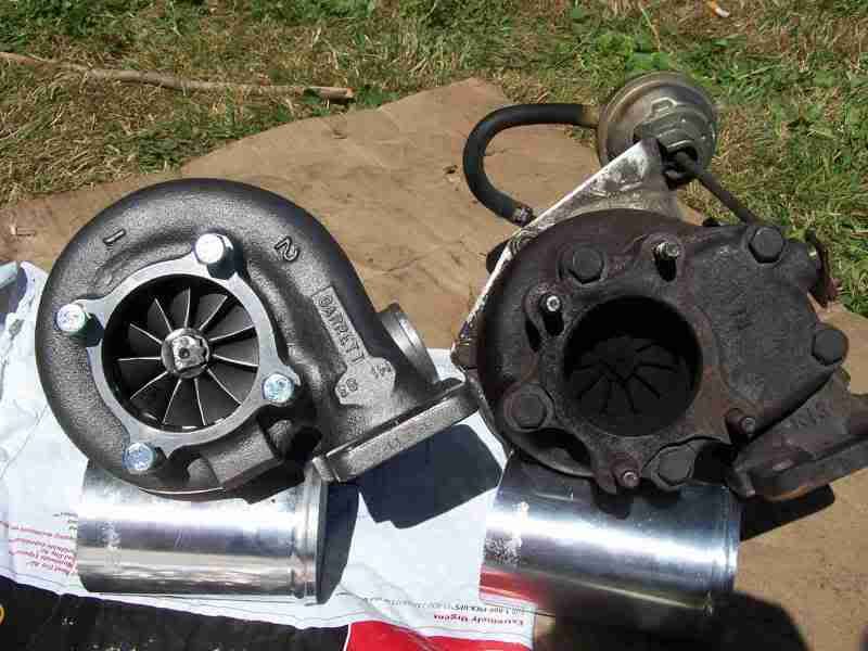
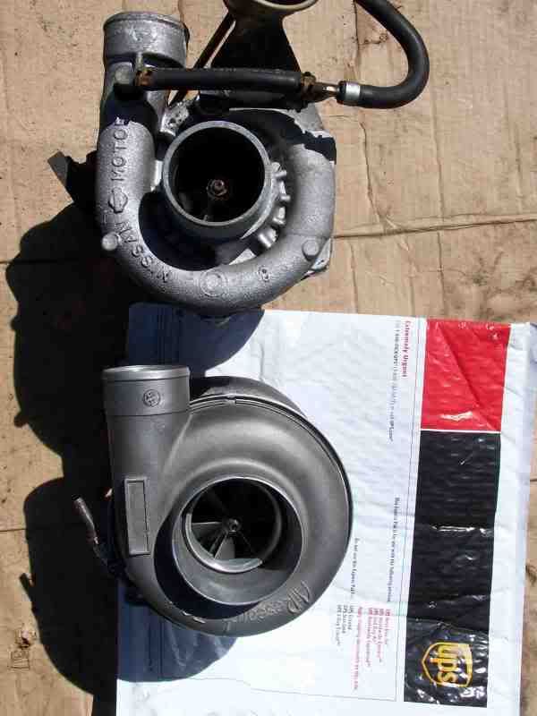
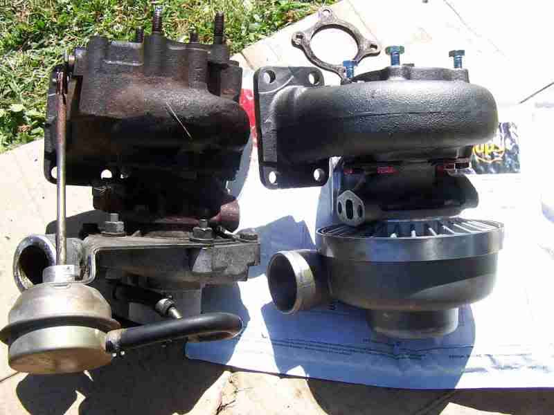
Well here it is with the new P-trim T3 housing.This picture does the old T3 to much justice, That turbine is tiny.
Now I'm messing with the wastegate adapter, trying to figure out the best way to hook it up to the manifold. I think I have a way to do it without welding but I'll find out in a second.
...Nope it's going to be welded on.
-
thanks again. I ordered them. Summit has a great return policy if all else fails. Thanks for all the help you have given me on this project. Goldoldjam and Rs speed you guys have basically hand held me through this whole project.
Glad to help some, hopefully it goes nice and smooth. Looking good so far, remember to take some more pics and show us how it turns out.


3" exhaust 3 45 bends.
in Exhaust
Posted
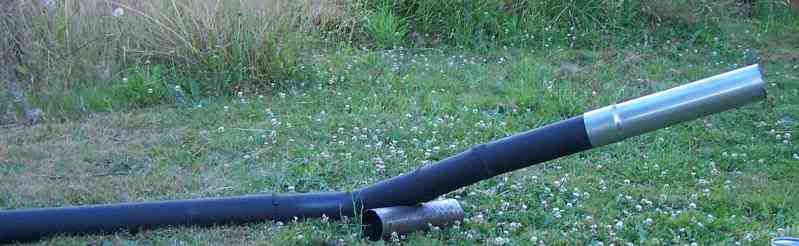
Last couple pics.
Screamer Pipe routing
Bad picture of wideband o2.
Muffler.