

duragg
-
Posts
1201 -
Joined
-
Last visited
-
Days Won
7
Content Type
Profiles
Forums
Blogs
Events
Gallery
Downloads
Store
Posts posted by duragg
-
-
Pictures.
The weights. Except for different springs seem identical.

The shaft. Yes, by design it has different slots.
But somebody has welded the shorter slot shorter.
My issue with this is that when the first weight hits its stop, the other weight is free to continue tugging on the arm.
It can't go far, but it can probably bounce around enough to making the timing dance a bit.
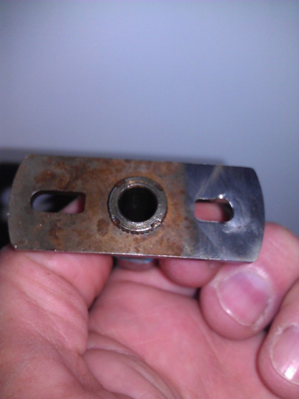
Machine shop has the parts and they are going to weld and recut so the slots are both equal.
Both weights will be on their stops when the advance is all-in.
If (or when) this doesn't help or make it worse you an all laugh at me and say "we told you so noobs".
-
They slots are supposed to be different. See page EE-32 in the service manual.
It might not help timing stability, but it is factory.
Those pictures are all a "dual points" dizzy.
I have a single points dizzy. Would like to compare FSM pictures of the two.
FSM says they have different centrifugal system.
-
You mean to tell me this party's been going on for ages and I just found out about it!!
-
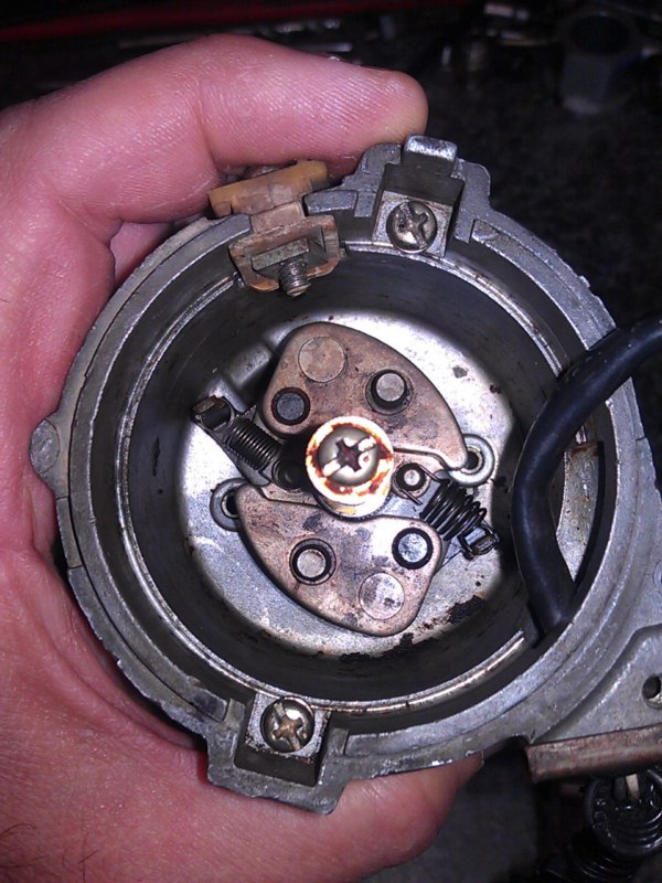
Hard to see in the picture, but one slot is closed down a bit and the other is standard length.
So when the first peg gets to full advance, the second is still being TuggeD on by the other weight.
Uneven tugging on the centrifugal advance cannot make timing any MORE stable.
-
Look closely in the picture below, the slot to the upper left has a small "thing" limiting the centrifugal advance.
But the slot to the bottom right does not have any limit.
I see no reason not to weld both and recut the slots to precisely the same length to give the total advance range I want.
Lots of articles on the internets about timing bounce.
I think this is (one of) my problem.
Perfectly stable until near the centrifugal "all-in" point. Then bouncy.
INcreasing further RPM past that and the bouncy lessens (as centrifugal force exerts more control).
Soon it will be known.
-
Pulled and inspected dizzy and everything is tight.
Vac advanced plate is fixed. No movement possible.
What I did notice is the mechanical advande slot on one side is welded to limit advance, but the other slot is not. So one weight has additional advance it could go if not for the weld on the other side.
Perhaps at certain rpm the lack of constraint of one weight is causing vibration of the other and making the scatter I am seeing.
-
Awesome.
That must be how they make propeller spinners.
Very cool.
-
Look down at the end of this thread: http://forums.hybridz.org/index.php/topic/102744-crane-xr3000-stable-vs-hei/
I did some work phasing my optical ignition and it helped.
I had phased it to TDC instead of the actual timing part.
Tj
-
Keyword "DRW" got me to the thread I was searching for. THanks for that tip.
Question: Why would racers want a cheap steel wheel? They just beat them up and want to beat them and then toss them?
Or have lots of differnt rubber already mounted?
Thx.
Tj
-
So I'm not crazy?
Looks like a 15" is the biggest.
Need to pour through 25,000 posts about what will fit inside ZG Flares with stock struts.
I just want big fat wide rear and maybe 8" wide up front.
-
I saw a picture of a Z with what looked like a plain steel wheel.
I really liked the look, simple, flat black..
Is the problem with those just the weight?
http://www.bassettwheel.com/dhole_asphalt.html
Seems like this company has something that would be simple, clean and cheap for a rat-rod type look.
I like the idea of a 15x8 front and 15x10 rear or along those lines...
Doesn't seem like these weigh much different than the group buy Rotas?
-
Vacuum advance is gone.
Previous Owner fabricated some little arm to lock the plate.
I will install this solid breaker plate and do the other mods and report back.
Tj
-
Just bought a rebuilt single points Dizzy from "510Doc".
Ordered solid breaker plate from NISMO.
Replacing front pulley
Get all the little stuff done and go from there.
Thanks again.
Tj
-
Very helpful, thank you.
So I will pull the dizzy and drop off at the machine shop to get rebushed.
Or do I just buy a new one, and install my eyeball in there?
Not opposed to spending some money to have nearly perfect ignition as reduction in variables only contributes to Triple DCOE performance.
(edit: $150 ish to fix a dizzy is fine (my machine work is free). SPending over $150 makes me think crank fire.)
... Yet again, building an entire car around 3 italian carbs!
I wouldn't have it any other way.
Unless I win the lottery and install: www.imagineinjection.com
-
Today:
Pulled valve cover and verified Cam mark and piston #1 at TDC.
I made a more distinct white ZERO mark on the pulley and indicator to line up #1 TDC mark.
Switched to B8ES at .041" gap plugs.
Started the engine and set timing max advance at 34btdc (elevated RPM). This gives me about 14 Initial.
I then phased the rotor to the Cap and shot this video.
What you cannot see:
* Using a Snap-On variable timing light to keep the white marks on the pulley aligned at Zero.
* Then reading the timing from the dial.
* Then shooting the light at the cap and you can see the rotor alignment is better (without touching the dial / same rpm).
At idle and up to maybe 2000rpm the timing marks are rock steady.
From maybe 2000 up the timing marks starts to jump around quite a bit.
Much higher rpm is steadies a little bit, but not rock solid.
Rotor cap for testing.
Felt a lot better driving after this. But still concerned about those marks jumping around.
-
Due to corrosion by the water pump I put an L24 front cover on my new F54.
Dry check the fit real well.
-
A guy named Bob Ream here in Phoenix makes a pretty neat ITB EFI called: Imagine Injection.
www.imagineinjection.com.
His system still has a vintage look, but is all electronic.
I do find myself rearranging my life to tweak the triples (like all day today planned!)
-
Thats pretty cool. I need to do the same with my new L28 motor running the same Isky Cam.
I have a wideband in my car and my butt feels like best power is somewhere in the 11.5 to 12.5 AFR. Similar to what you have there.
My sensor bottoms out at 10AFR.
What timing do you have in it?
THose charts are corrected to Sea Level, Standard Temp and Pressure already (normally). It says down at the bottom left "* Correction Method: Standard".
In the airplane world that means SL, 15c and 29.92. Not sure what exactly they would use.
-
If I recall my machinist had me use 1.8 to 2.2 thou (.0018"-.0022") on my motor 3 months ago.
The engine was a fairly recent rebuild and when disassembled I found +.50mm pistons with .004"+ piston to bore (sorry for mixing units)
We blew it out the bores to use +1mm pistons and the tighter clearance.
-
Can you who race them like this please explain your pre-race tune procedure?
Check timing?
Pull Plugs?
Check valves?
Re-sync?
It has to be a lot easier if you really don't care about part-throttle manners and mostly concerned with WOT.
TJ
-
I'm not sure of anything with 3 DCOEs.
I am running a mix of 100LL and 91 pump gas (50/50).
Wideband shows low 12s at that time.
This motor just seems to pull hardest in the low 12s.
Starts sneezing in the mid 13s.
Could be one carb over or under contributing, but all plugs look similar.
Could be the O2 sensor getting funky from the lead in the 100LL
Could be just the way triples run and want to be richer.
So, today I will recalibrate the timing again and do the phasing procedure on the Optical wheel again.
Will also hunt down some different plugs and gap up to .040 or something.
Appreciate the help.
-
Seems under full power the thing is pretty stable.
But idle and part throttle - say holding 3000 and waiting to stomp I can hear a little messing around.
I wonder if that is in the helical gear on the crank or the half-moon higher up?
Worth trying to tighten up?
I think I can find a way to tighten up the middle joint easier.
-
I am almost embarrased to share this video.
I just now took a video of my rotor bug.
Something tells me the motion is excessive (please don't hammer me... I'm kinda new).
Am I toast with this?
-
Summary:
Crank trigger or a fancy machined wheel in a perfectly new Dizzy is best.
A well running Crane or other dizzy based system for a hopped up street car should be fine perhaps.
Thinking about all of this I will go back and re-do the "phasing" and make sure everything is tight in my current dizzy and see how that goes.
Appreciate the input.
Tj


Crane Xr3000 stable vs, HEI?
in Nissan L6 Forum
Posted
The new Hot Wheels are made in China and they no longer use Nitrogen Charged shocks.
You tried sourcing NOS N2 charged hot wheels shocks? Insane expensive.