
Dragonfly
-
Posts
674 -
Joined
-
Last visited
-
Days Won
1
Content Type
Profiles
Forums
Blogs
Events
Gallery
Downloads
Store
Posts posted by Dragonfly
-
-
Hi DragonFly,
what do you call the waterpump you have there? with the pulley on your engine? Thanks
It is this one made by Moroso http://store.summitracing.com/partdetail.asp?part=MOR%2D63750&autoview=sku it will require a couple of modifications. You have to decrease the diameter of the stock water pump mounting plate (where the black pully is mounted) you will have to drill holes in the black pulley to line up with the holes in your stock water pump mounting plate, you will also have to notch the support ribs on the backside of the stock water pump mounting plate to clear the black pulley. Also you will need to use the larger diameter electric motor pulley offered seperately from the kit. I made my own mounting brackets out of aluminum in order to clear the engine block which required me to need a longer belt (purchased from McMaster Carr).
All combined including the cost of a new stock water pump I paid around $150 for the whole thing which is $100 less than the price of the CSR electric pump which is a direct bolt on. http://store.summitracing.com/partdetail.asp?autofilter=1&part=CSI%2D928&N=700+115&autoview=sku
BTW when I did mine it was before the CSR was offered for the Z or I would have paid the extra money for the CSR.
Dragonfly
-
Well I decided that I wont be using the grill and block off piece I made. Anyone want it? $15 + shipping will take it.... Its painted with undercoating and looks nice.
How come the change of heart? Although mine is a little different than yours it works quite well and I would think your design would also work well.
I'm looking at doing the reduced air intake, and a couple of thoughts. Any angle greater than 15 degrees on the duct is going to cause turbulent flow, which will reduce the effective size of the radiator as the turbulent air around the edges will have trouble going through the rad (actually, intercooler in my case). Given the space limitations, the best solution would appear to be to have two ducts, one feeding from above the front bumper, and one below, both tapered at a max of 15 degrees, and feeding the upper and lower halves of the intercooler/radiator. That way I can have the smallest air inlets without losing out on intercooler/radiator area due to turbulent flow. Thoughts?Note : this is just from eyeballing the front end, I still need to check angles from above/below the front bumper.
I personaly don't think seperation of the air getting into the radiator/intercooler is going to be a big deal since they are such a huge obstruction to airflow, using hypathetical numbers off the top of my head lets just say that you are getting airflow into the radiator at 50 mph your downstream side will probably only see about 15 mph so with that much air getting stopped by the radiator you are going to have turbulent air no matter how much you manage to streamline the flow. That is part of the purpose of blocking off so much of the open area in front of the radiator, if you can reduce the volume you can reduce the amount blocked which in turn reduces air wall in front of the radiator so more air is able to push through rather than requiring a fan to pull stagnant convectionaly heated air through.
The idea of using two ducts to me would not yield any improvements unless you mounted your radiator and intercooler in a V configuration and had one duct feeding the radiator and the other duct feeding the intercooler. All the above is my opinion, you are more than welcome to prove me wrong but I'm feeling fairly confident.
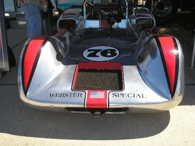
One last comment... I watched this car run several laps racing and he never overheated and I know he's got some crazy angles going on there.
 BTW thats an oil cooler you see in the duct on the right hand side back by the drivers seat.
Dragonfly
-
The doors have three (I think) drain holes at the bottom. You should open the door panel and clean out the bottom inside of the door.
Funny, people in CA don't know what to do when it rains! LOL. Just Kidding.
Sure we know what to do... freak out, panic and run into things... isn't that what everyone else does.
PhilbertZ, like cygnusx said you need to open up the drain holes in the underside of the doors.
Dragonfly
-
I probably will be embarrassed for asking this question, but it's bothered me for some time now. When I adjust my valves I use a crow's foot open end wrench and my click style TW. This discussion has revived my concerns that I overtightened my values due to the added offset. What is the proper manner to torque the valve nuts?
The calculator that I linked in post #10 of this thread should take care of that question for you.
Hers a question, once tested, is the snap type TW actually adjustable is its needed to do so. If so, how do you do it.Ferd
Yes it is adjustable and I would highly recomend that you do not try to adjust it. These wrenches have a spring on the inside of the barrel of the wrench as you turn the handle you compress that spring against a fulcrum that sits on a specialy designed base, the fulcrum is pressed into a precisely cut notch in the shaft of the head piece that is inside the handle below the pivot pin that holds the head in the wrench. When the correct amount of force is reached the fulcrum will allow the head to rotate from iits neutral position to the side, it does this with enough force you can hear and feel it "snap" or "click" which is why it is called a snap or click type wrench.
The adjustment for this is in the handle, on most (but not all) snap type wrenches there is a metal similar to solder that is melted into the very bottom of the handle to hide and protect the adjusting nut, you have to melt this metal out of the handle, with the handle locked in position break loose the hollow allen head screw, then you tighten or loosen the adjusting screw undernieth it through the hollow portion, lock the set screw back down and test you adjustment, repeat the above procedure untill the wrench is within tolerance then re-melt the metal back into the base of the handle.
If anyone tries the above procedure without the proper calibration standards to verify the adjustments made you can safely know that you have turned your torque wrench into a ratchet that makes a loud click every now and then.
another thought, why is the TAM so 'trustworthy'. Why is it that the electronic device never goes out of adjustment?It's not... it just doesn't have as much exposure to the general public and therefore people do not know as much about it. I can assure you that electronic devices go out of adjustment as well.
Dragonfly
-
I used my Kent-Moore Torque angle meter to spec out my two other TW's. Since the electronic TAM is supposedly always adjusted correctly, I used my other TW's on the TAM while it was installed on a vise.
Damn they were both pretty much on the money. However, what I learned from doing this is you really have to finese the readings. IOW, nudging up, lubricating the fastener (if required), will give a more accurate reading.
Are your two torque wrenches "snap" type wrenches? If they are you should prior to checking them against a standard (or in this case your TAM) set them to max torque (150 lb/ft in your case) and pull them untill they snap (break over) a minimum of 6 times. The reason for this is to reduce the potential for frictional binding of the fulcrum/head/pivot inside the wrench. This is only required when calibrating because a typical bolt or nut that you are going to torque will have a range i.e. 140 to 160 lb/ft in which case you set your wrench to 150 lb/ft, if the wrench is off by 6% instead of the 4% that it is supposed to be within then you are still within the spec of the bolt (6% of 150 is 9 so you can be between 141 and 159) but during calibration you can not be beyond 4% or 6 lb/ft at a setting of 150 lb/ft hence the reason for breaking it over 6 times prior to taking a reading.
BTW I do this stuff for a living.
Dragonfly (the metrologist)
-
About 6 or 7 months ago I was in the wrecking yard getting ready to pull a rear differential. I had gotten myself situated under the car so that I had plenty of leverage, about a foot away from me is a welded stack of rims that is supporting one corner of the car (the wrecking yard uses 4 to 5 of these welded rim stacks to support the cars so customers can safely work under them), just beyond my head I had noticed a spider web... well as I start to work little miss black widow steps out to see whats going on, at the time I have every once of my energy pulling a breaker bar trying to break loose one of the bolts. Being about as aracniphobic as any one else I spotted the spider and all my attention went to her at which time the socket slipped off the bolt and I slammed my elbow into the bead of the welded up rim stack beside me. The black widow apperently did not find that to be entertaining so she went back to where she came from. I did get the diff but I still have pain in that elbow from time to time.
Dragonfly
-
I hope not!!-supermetalium is grease lol!
http://www.preferredindustrial.com/SuperMetalium%20products.htm
Ah crap I can't even make up a good fake super strength metal. Maybe it was that other metal "unabtainium".
Dragonfly
-
Here we go, pick it up at Sears
http://www.sears.com/shc/s/p_10153_12605_00986520000P?vName=Tools&keyword=torque
I think that picture is either deceptively small or they made a mistake with the numbers. The 3000 lb/ft torque multipliers that I used to calibrate took two people just to lift them. Also in the picture that looked like a one inch drive which would be very short lived at 8000 lb/ft, or maybe the thing is made out supermetalium and that is why it cost so much.
Dragonfly
-
I think I am going to buy a beam TW if they make them for 180 lbs or more? Is this a good choice?
Yes and yes, they do make them and it is a good choice. I personaly will recomend that you look at the Craftsman (Sears) beam type wrench as it is one of the best out there and is a decent price. If you find one and you have never heard of the company that makes it (and its cheap) pass it up, they can not be adjusted.
Dragonfly
-
Just to add, beam type torque wrenches hold their calibration better than the click type. Makes them a better choice for the average motor head who doesn't have access to a calibration lab. They are cheaper too.
FWIW, the Navy required all torque wrenches used in the reactor plant to be recalibrated every 6 months.
You got that exactly right (in bold), the beam type is the most durable and has to be physically damaged to cause it to go out of calibration, but if it is ever damaged it can not be repaired and should be thrown away.
I never calibrated any of the Navy's reactor plant wrenches but the wrenches used on launch vehicles (rockets) have a 3 month calibration cycle.
Dragonfly
-
Found a good link with a calculator and explination http://www.norbar.com/torquewrenchextensioncalculator.php
Dragonfly
-
look you can buy what you need fairly cheaply, Ive got several TQ wrenches, and youll be surprized but most sears/husky/and similar priced tq wrenches are fairly consistant and reasonably accurate, and if your off by 1% or so IT WON,T MATTER A BIT
You are correct in that 1% won't matter. The wrenches that you are describing have a stated accuracy of 4% indicated value (IV) in a clockwise direction and a 6% IV in a counter clockwise direction. What is more important is repeatability which is what you get when you use a better built wrench which is what you get when you buy a better brand wrench.
Dragonfly (the Metrologist)
-
I pretty sure that this won't work - the torque wrench is still going to read or click at the torque it sees at the socket end. Adding length will only change how much force you have to apply to get it to read a given torque. If the wrench maxes out at 150 then you need a bigger torque wrench.
I was a little concerned that it would not be understood which is why I also suggested borrowing one. The way it works is that you do not add the length to the handle of the wrench but rather you add the length to the wrench by attaching an extension that would look something like this O----C onto the 1/2" drive, this extension is parallel to the wrench handle not 90* from the handle. By doing that you have effectively increased the amount of rotational force (torque) for the same amount of force (weight i.e. how hard you push or pull the wrench), by doing this you can not use the dial or click to read your torque value you have to calculate the value.
Here is a link that gives a pretty good explination with pictures. http://www.specialpatrolgroup.co.uk/spooky/torque/torque.html
Dragonfly
-
Torque = force X length. With that if you were to increase the effective length of your torque wrench you could achieve the torque you want. Since I don't know how long the effective length of your wrench is I can only guess but you will need to add aproxamately 1 1/4" in length to the wrench. The easiest way to do that is to get an offset crows foot but that would be very difficult to use on the crankshaft bolt.
Probably the best thing to do would be to go to a parts store and ask them if they have a tool loaner program then borrow a 200 ft/lb torque wrench to do the job.
Dragonfly
-
That mount looks great. Good job on getting the car running.
Dragonfly
-
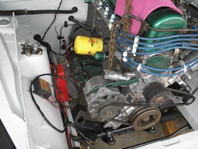
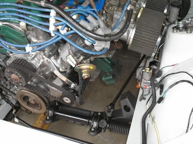
Here's a couple shots of mine with tie wraps used to seperate the wires.
I agree with katman about the crossfire issue, it may not happen right away but it will happen sooner or later depending on the quality of the wires.
Dragonfly
-
Being on my second seal (#2 from pic), I am getting very tired of my car marking its teritory everywhere I take it. It looks like I am going to have to make a trip to NAPA to get one (or maybe even two) of these newly discovered (located) seals (#4 from pic). Thanks slownrusty, I thought that after the transmission shop could not find the "right" seal and I could not find it I would just have to "live with it". Great job.
Dragonfly
-
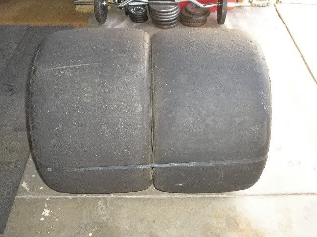
I think fatties look better under Yellow and on all 4 corners…
Yep BRAAP your car is what I had in mind when I got my fatties. I have since decided that I am not going to cut up my car enough to make them fit, plus if I got my car that wide I would flatten every cone on the track.
Dragonfly
-
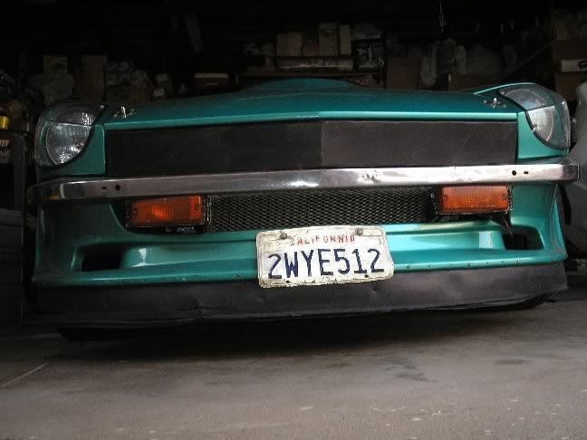
I have a 280Z airdam on my 240, I just modified a set of 280 turn signal lights and attached them to the underside of my bumper.
My car is not a show car by any means so I am happy with it like this.
Dragonfly
-
For sale is a Datsun 240Z 1971 . Needs much work. Has rust and needs body work. Runs good and drives good too. Currently registered. Sold on lost Title Salvage. The larger tires and wheels not included. Thanks,
Awww darn... I wanted the tires for my car... actualy I have some that wide in the shed.
Oh well I guess us San Diego people like our tires wide...
Dragonfly
-
I got to see one in person the other day. My opinion was the car is kind of ugly but... when I saw it in person it actualy looks pretty good.
Dragonfly
-
We are on the dyno again later today and tomorrow so I'll get a new printout. (around 1500nm @ wheels last time I think)
Rob
I just ran that through a conversion calculator for myself and the others on here who just can't quite comprehend 1500nm... here's what I got
Now thats some numbers to be proud of no matter how its written.1500 newton meter = 1106.343 pound footDragonfly
-
Here is a link to Les Canadays website http://www.classicdatsun.com/. Les is the owner of classic datsun and the guy who purchased all the remaining stock of R190's and parts for them from Nissan, Les also probably knows more about that particular diff than anyone else. I did notice that he doesn't have anything about them on his website but if you were to call him or email him I am sure he could enlighten you quite a bit.
Dragonfly
-
AP-300
ROLITE'S Best Aircraft Aluminium Polish on a 6060-T6 panel.
ROLITE'S "AP-300" is the ultimate polish / protector developed specifically for bare aluminum surfaces. Roliteâ„¢ has developed this polish to give the best possible finish and protection on bare, Alclad aluminium, exterior aircraft surfaces. Quick and easy to use. Polishes & buffs right to a finish without having to " wipe out the black" in a separate step. Developed specifically for use with "barrel" or "drum"(pg.3 & 12) type polishing machines. Meets the most recent commercial aviation certifications set by Boeing, McDonnell Douglas, A.S.T.M. & Bombardier Aerospace (MPS 120-136)
This is the latest version of the stuff that I have been using for years, as you can see it is a protector as well as a polish and it is designed specificaly for bare aluminum. Because this is made for aircraft you may not be able to just go out and buy some (I got some when I used to work at General Dynamics), here is the link to where I got the above from if you would like to try: http://www.aircraftpolish.com/specrolite.html
I also feel that like others have said... get away from the acid, is the best advice.
Dragonfly
 BTW thats an oil cooler you see in the duct on the right hand side back by the drivers seat.


 AP-300
After doing some reading.. I blocked off the upper grill *pics*
in Windtunnel Test Results and Analysis
Posted
mopar69, I think that you are right about the air building up in front of the radiator and that is why I refered to that air as stagnant and heated by convection, the only real way to get it through the radiator is with a fan and IMHO the only time you should use a fan is when you are stopped. That is why you should reduce the opening in front to a much smaller size so all (or most) of the air that goes in goes through the radiator.
mjfawke, I'm looking forward to seeing the pics you were talking about. I also have an idea in my head that would probably cause you a ton of work if you decided to try it. You said you have a 2cm gap between your intercooler and your radiator (high pressure area) and I am guessing that the radiator is on the engine side of the support and the intercooler is on the opposite side of the support. You also mentioned the bumper and using that as a dividing line for the two air intakes... So here's my idea...
leave the bottom of the intercooler where it is at but rotate the top towards the front of the car until it gets within a cm or two of the front bumper, mount it in that position, from the bumper down build your air intake for the intercooler, then from the bumper up build your intake for the radiator (provideing you with a modified V). The upper intake floor is also the lower intake roof and should start at the top of the bumper and go upwards at 10* until it contacts the radiator (use foam weather stripping to protect the radiator from the end of the metal sheet). It sounds like you have two fans "thermofans" so try to place them so one is above and one is below the division point of the air intakes.
The lower half of your radiator will receive hotter air due to the intercooler but no more so than the entire radiator is in the current configuration, the upper part of the radiator will receive only cool air that has not passed through the intercooler which should help to lower the engine temp. The space between the intercooler and the radiator will allow plenty of room for the air to pass through the intercooler but will not provide a whole lot of pressure to push the air on through the radiator at that point, that is why you should put one of the fans there, not only will the fan suck the air through the radiator but it will also leave a low pressure area behind the intercooler for the air from the lower air intake to try to fill.
I hope all that makes sense and I know that it would require modifying your intercooler piping which would be a huge PIA but at the same time it could be worth it.
Dragonfly