
Dragonfly
-
Posts
674 -
Joined
-
Last visited
-
Days Won
1
Content Type
Profiles
Forums
Blogs
Events
Gallery
Downloads
Store
Posts posted by Dragonfly
-
-

Your looking a little "stoned" in this shot... must be just a shadow of your true self...
Ok I'm being a smart...
Dragonfly
-
Inside a ballast tank on an offshore oil rig
Mr. Tough Guy, a couple of days after the above photo
At the Grand Canyon (undoctored photo)
My wife and I having Valentines dinner (I clean up pretty good when my wife can get me away from dirt, grease, cars...)
Dragonfly
-
I just took the time to read through this article in detail, and it is a really interesting procedure - I hadn't really considered trying to mix and match the components - very thorough.
I did notice one thing, though (and I kinda hate to even mention it, considering how much time you put into it)...
When coming up with the balance figures, I believe that you should only consider half the weight of each spring, as one end of each spring is always stationary - this is the same rule that you use to figure the spring's contribution to the unsprung weight in your suspension. Also, same reason that you use the "levered" weight of the rocker.
Sorry to bring this up, but I figure if you're gonna be anal, you might as well be really anal...
Youv'e got a good point... but I could not figure out how to accurately weigh only one half of each spring. In doing it the way that I have outlined you still end up with an overall tolerance of + or - .25 gram from your nominal value (weight) you just have to deal with the fact that the mass that is moving is actualy less than your nominal
.Great Article Miles!Stiky! Stiky! Stiky!
I take this as one of the highest compliments I can get, thanks Tony and thanks admins for making this a sticky.
Dragonfly
-
Any chance that a balance with an accuracy down to .01 gram will cut it for this job? obviously the greater the precision of the scale, the greater the precision of the results...
Nice write-up! Somehow I doubt it will be among the more frequently UTILIZED write-ups here, but thats just because too many people are too lackadaisical with their engine assembly. Thanks!
The .01 gram is not going to help you much (it is equal to 10mg) but it is still much better than stock. You may be able to find a fairly cheap jewelers scale and use that for the smaller measurements than use your .01 gram scale for your larger measurements. A jewelers scale will usualy allow you to select grams, mg, or carats, if not you will have to convert. You are correct that the greater the precision the better the results.
One question.. You say "front to back," do you mean from the left to the right in this picture? Pivot end towards valve end and vice versa, as opposed to "top" and "bottom" in an assembled sense?Yes that would be pivot end to valve end, the reason for that is that all of the microscopic (and larger) lines that you create from grinding and polishing are moving along the load bearing axis and therefore will not weaken the part. That is even more true if you do the same thing on connecting rods, always work from end to end.
Dragonfly
-
Glad I could help.
Dragonfly
-
After reading (and posting most of the same pictures) this post http://forums.hybridz.org/showthread.php?t=126226 I decided to post the above "article" that I had written a long time ago but never got around to posting.
Dragonfly
-
VALVE TRAIN BALANCING
Many of you who know me have heard me say that the valve train in my engine is balanced to within + or – ¼ gram. Well I am going to tell you how I did it,
First you need to have access to a very accurate balance (or scale), and you need to make a fixture to allow you to check the “levered†weight of your rockers. The other things that are very handy are a computer with excel and a tray (or several trays) with at least 84 total compartments (this is for an L series motor). Each compartment should be numbered from 1-84 using some sort of permanent marker.
The next thing you need is to purchase a brand new set of rockers including all accessories i.e. retainers, valve springs, lash pads etc., it is important to buy high quality parts, preferably Nissan parts although mine came from Motorsport. It is also a good idea but not necessary to purchase a new cam at the same time.
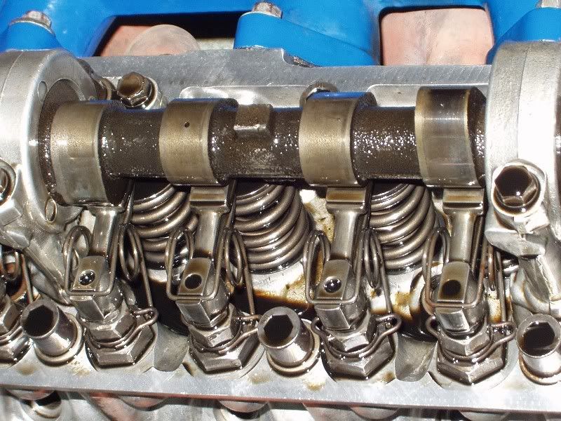
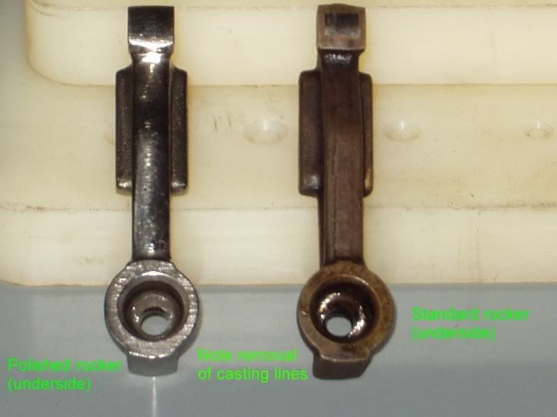
Assembled rocker assembly with lightened, polished, and balanced rockers and components.
You can see in the above picture what the results of all your hard work will look like, so lets get started with what you need to do now. Since you have all your new parts it is time to put your tray(s) to use. You can use any order you want (but I started with my rockers, then retainers and so on), and put one piece in each of the numbered compartments (each half of the retainer locks gets its own compartment). Also you should separate the valve springs and give each spring inner and outer its own compartment. Make sure each piece is completely clean and free of all foreign materials including any oil or rust inhibitors. Now on a piece of paper write the numbers 1-84 (if you have sticky labels you can use them and stick one inside of each compartment), weigh each piece you have at least three times and average the weight then write the weight on the paper or the label. For your rockers this is the unadjusted weight and it will change. After you are satisfied with the weights you attained put some oil or WD-40 on the parts so they do not rust.
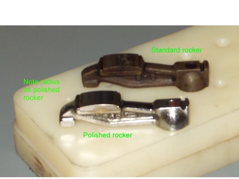
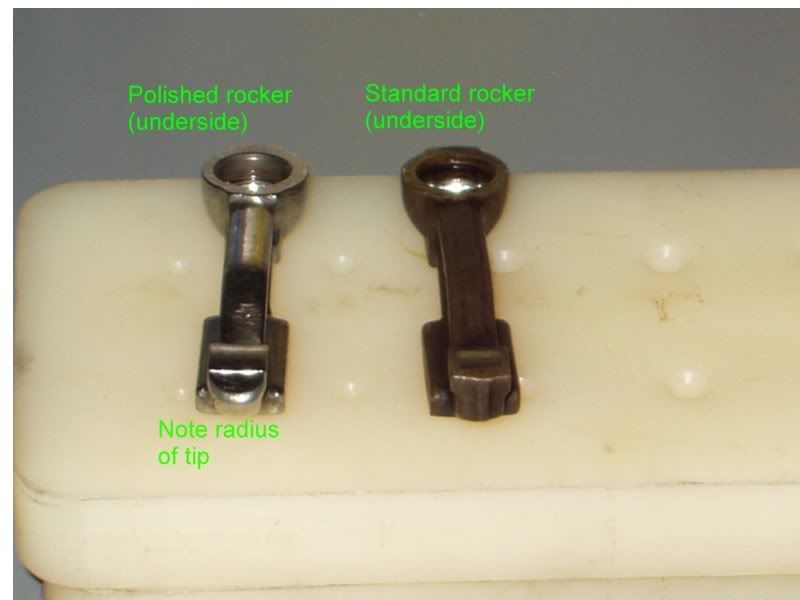
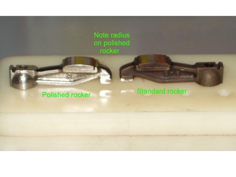
Inspect each rocker for any defects and make sure the braze that holds the wear pad on the rocker has no gaps in it. Put a piece of masking tape over the pad on the rocker to protect it. Take the rockers one at a time and using a grinder wheel with a medium grit wheel very carefully radius the tip as you see in the pictures below.
After the tip has been ground down weigh each of the rockers (pull tape off before weighing) again as part of the goal is to get the weight of each rocker as close as possible to the next. Re-tape the rockers and using a Drimmel tool with a small diameter drum sander remove any and all casting lines and sharp edges (except the sides of the pads) from each of the rockers, while doing this you should make sure that you work front to back and NOT side to side. All the sanding marks should run front to back when you are finished. Again remove the tape and weigh each rocker, as you have been grinding on the rockers you should be biasing the material removal on the pivot side of the pad in order to bring the weights closer to each other. Once everything looks more like the above picture 1.2 and your weights are within ½ gram of each other it is time to start polishing the rocker. You will polish at this time only the pivot side of the rocker. Start by using a very fine sanding drum on your Drimmel then go to grit impregnated rubber polishing wheels and lastly to a felt wheel with polishing rouge. Remember to always work front to back and NEVER side to side, when you are done the pivot side of the rocker should look almost like a mirror and you should not be able to see any sanding marks in the metal.
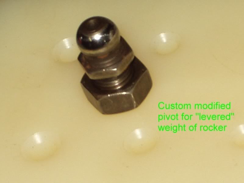
Customized pivot for measuring the “levered†weight of a rocker
Now it is time to weigh the rockers using the “levered†weight fixture (picture above), make sure the rocker and the fixture are completely clean with no traces of any foreign material. Place the fixture next to the scale and adjust its height so the rocker sits level between the fixture and the surface of the scale, make sure the rocker only contacts the scale with the tip. Carefully and lightly tap the rocker on the pad with a pencil to make sure its full levered weight is resting on the scale, write down the reading on the scale then remove the rocker and do the same thing again with the same rocker, do this at least five times for each rocker then average the five readings. After you have an average levered weight for each rocker you now need to radius and polish the valve end of the rockers to bring the weights down to within ¼ gram of the lightest one. When you are finished with this last step record the levered weights of the rockers, apply oil or WD-40 to them and place them in their respective compartments.
After you have each item numbered and weighed you need to fire up your computer, open excel and create a series of 84 cells numbered 1-84 and containing the weight in grams of the piece assigned that number. Using a calculator add the weights of a group of items together then divide that number by the total number of items to get an average weight, as an example I have 12 retainers and their weights are (in grams) 26.966 + 27.139 + 27.240 + 27.312 + 27.413 + 27.590 + 27.645 + 27.737 + 27.814 + 27.878 + 27.998 + 28.106 = 330.868 divide by 12 = 27.572. After doing this with each item i.e. inner spring, outer spring, rocker levered, lash pad, retainer, keeper left, and keeper right (do NOT use the rocker actual weight) add the average weight of each item together to get an overall average weight for example 155.293 grams. This weight will become your target weight for each rocker assembly. Now comes the real fun…
Using the excel spreadsheet you created with all your weights in their own individual numbered cell you now need to mix and match parts together in order to achieve your target weight of -in our example- 155.293 grams plus or minus .25 gram or in this case 155.043 to 155.543. You may find that no matter what combination of parts you use (you have 7056 possible combinations) you can not get all of them within the .25 gram tolerance, if you run into this case look for any individual part that is notably below or above the weight of all the other parts and use the difference in weight from the other like parts divided by two to bias your average and use that as a new target weight for your rocker assembly.
This whole process took me approximately three months to complete and left me with a rocker assembly that weighed in at 153.644 grams with the greatest plus weight adding .211 grams and greatest minus weight being .212 grams which falls well within my tolerance of plus or minus .250 grams.
This exercise will not provide you any extra power from your engine, but it will increase the reliability and longevity of your engine plus the reduced weight will lower your overall engine mass allowing the engine to rev quicker and smoother. Do not attempt to do this if you do not have the time, tools, patience, room and or ability as it is not an easy job and it will not go quickly, but you’ve got to love the bragging rights.
Miles Gray
(Dragonfly)
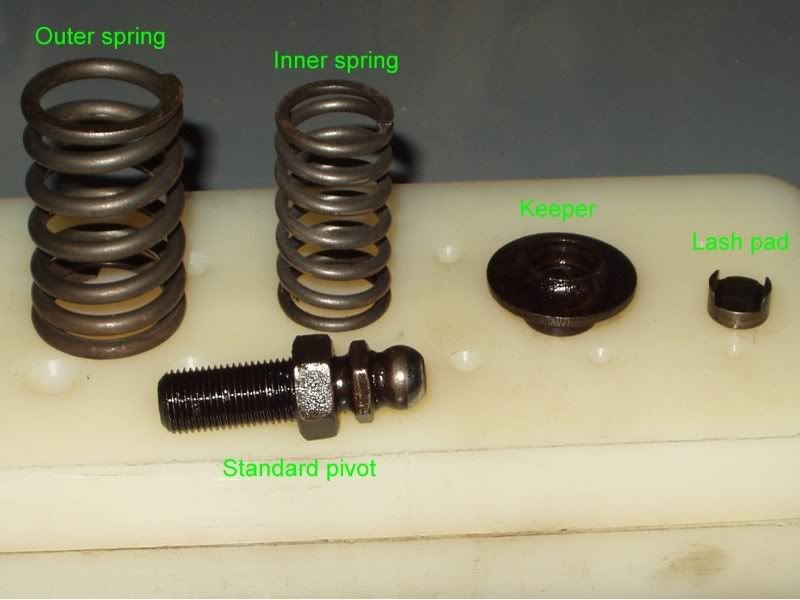
Springs, standard pivot, keeper, and lash pad. All but the standard pivot should be weighed as they are all part of the balancing process.
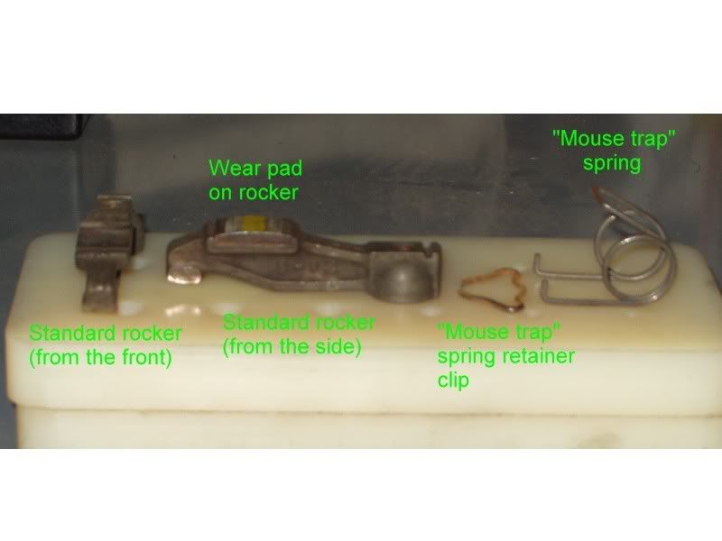
Unmodified rockers from the front and from the side, mouse trap spring retainer, and mouse trap spring. Only the rockers are weighed.
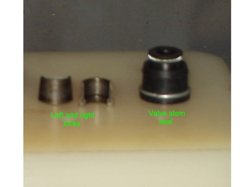
Left and right retainer locks and a valve stem seal. Locks should be weighed individually, the seal does not need to be weighed. *Locks are also referred to as keepers*
Mettler single pan balance that I used for weighing all my parts. This balance has an accuracy .1 milligram.
Dragonfly
-
I did mine several years ago and I have been beating them mercilessly ever since. Here are some pictures of mine (polished, lightened and radiused vs stock)
Dragonfy
-
Darwin award recipient waiting for his award to arrive...
Dragonfly
-
These newly painted cars are looking so good I'm going to have to go out and clay/rewax mine to make it look newly painted again. I'm jealous... looking great BTW.
Dragonfly
-
Wow! That looks great. Can't wait to see it running.
Dragonfly
-
Just to let everyone know this will get you into a Mercedes(sp) AMG car to drive on a race track under autox type conditions. These courses are usualy set up with an acceleration run then a hard braking zone followed by twisties to show you how well the car handles. The events that I have been to allow you to drive the car numerous times over a certian period of time. They also usualy privide food and drinks.
It just so happens that this event is in Florida and I am in California... I am just not going to be able to make it myself.
Dragonfly
-
Is this sort of what you had in mind?
Dragonfly
-
I originaly wanted to paint my car with a dragon type theme (and color) and call it "Dragonz" but that was just not working... so my wife suggested Dragonfly due to the similarity in name to Dragonz and the fact that at least half of the shirts I wear are made by the Dragonfly Clothing Company... example:
So the cars official name is Dragonfly which of course is my hybridz name.
Dragonfly
-
For anyone who is able to go to the "Homestead Miami Speedway
Sunday, October 14, 2007" I have a "pass code" for the first person who PM's me and ask for it. Please be sure that you can use it first. The pass code will get you into this website https://www.mbevents.com/intro.asp were you can sign up for the driving event.
Dragonfly
-
do you guys send the flywheel/pressure plate assy. out to balancing? . i was under the impression that all aftermarket flywheels are not balanced from the factory unless its specified ....
In general it is a good idea to have a flywheel balanced no matter who made it or where it came from. My Fidanza required a small amount of balancing, just a few bucks at a machine shop.
Dragonfly
-
I just did a more thorough exam of the Z and found a lot more damage to the front than I saw the first time I looked.
Both frame rails are pretty badly tweaked. There are visible bends on the bottom and engine bay sides of them right behind the cross member and the right tension rod bucket is twisted. The cross member and engine were pushed about 1/4" to the left.
All this indicates the front is going to need a lot of work to square it up and I don't have the equipment to do the job.
I'm going to do some thinking about whether to repair this car or transfer the drive train to another.
Ouch... thats going to be tough, my first thought would be to find a donor to transfer everything into but then finding a donor that does not have major cancer is pretty difficult. You may want to check around with some local frame shops and see what they say and go from there (while keeping an eye out for a donor).
Dragonfly
-
So i have the flywheel installed now on my 79 s130, combined with the centerforce 2 clutch. The problem i ran into was that hardware stores dont carry teh right sized bolts. so what i did was bought M8x1.25x16 grade 8.8 hex head bolts, and ground them down to 14mm length instead of 16mm, and then re threaded them. On installation i made sure they didnt bottom out this time, then used loctite on the final install. I ran out of time last night working on it, so i havent been able to test everything yet. I need a new slave cylinder before i go anywhere. ill keep yall updated though.
Sounds like you should be fine. As a precautionary measure you may want to make a plan to re-check everything after your break in period (500 miles typicaly).
Dragonfly
-
I'm a little suprised that there was a curb close enough to the finish lights that you could slide into it. I am saying that from the course designers standpoint not from a drivers standpoint, the course designers usualy put a lot of effort into making sure that everywhere a car may slide out at has a enough run off area to not hit anything. I am glad you are ok and your passenger as well (the soreness goes away after a week or so).
It is funny (coincidence) that I was autoxing Monday as well and although I did not hit anything I managed to blow second and third gears out of my transmission. The transmission was just rebuilt (by a local shop) last month, it will be going back again with a complaint.
Good luck getting your car sorted back out.
Dragonfly
-
Here is a clip that shows a scenario of what it might be like if a business meeting went like some forums go (with typical mods).
WARNING: Adult Language.
http://www.neatorama.com/2007/08/18/if-business-meetings-were-like-internet-comments/
Dragonfly
-
I have not driven or been involved with either one of the cars mentioned but I have driven and been involved with the Jag XK8 and the Mercedes C class. Over the years I have driven a lot of cars some of them costing in the 6 figures and out of all the cars I have driven the XK8 was the one I enjoyed the most as far as a combination of comfort and power/handling, but it had lots of little issues that added up to lots of dollars very quickly.
The Mercedes (all of them) are expensive to have work done on by someone else or yourself. A good friend of mine who owns his own shop has worked on them for years, he told me that of the "common" cars on the road they are the most expensive as far as parts go. On the good side though Mercedes are very comfortable, classy and if taken care of reliable.
Good luck (I know I did not actualy answer anything that you asked but I hope I helped a little).
Dragonfly
-
Wouldn't that bend the bracket? I only ask cause these bolts are really stuck in there. I mean for example, I had one of those flywheel locking tools that looks like this:
I had breaker bars on both the tool and the rachet plus I wired the tool to the flywheel just in case the teeth slipped. Well, there was so much pressure from both that the tool bent out of shape and is now useless.
So that's why I asked about the bracket. Sorry for the long question.Glad your mechanic can take care of it for you, but for your question above. I had that exact same tool and bent the hell out of it and almost ended up with a bloody knuckle situation. The bracket that I was talking about is about 1/8" thick stamped and hardened steel, you would have trouble bending that thing with a 16lb sledge hammer. I have done dozens of flywheels using the same one on both my engines and my friends engines.
All the information about impacts are good information but I personaly would not use an impact for tightening the bolts (any bolts) because of the lack of accuracy of the tightening torque. I use an impact for taking things off all the time but never to put them on.
A typical snap action type torque wrench has an accuaracy of 2% indicated value to 4% indicated value, a typical torque stick (used on an impact) has an accuracy of about 10% indicated value. So as an example if you are supposed to torque a bolt to 100 ftlbs and you use a snap action wrench you will be between 96 ftlbs and 104 ftlbs which is of course a span of 8 ftlbs but if you use a torque stick you will be between 90 ftlbs and 110 ftlbs which is 20 ftlbs of span. 20 ftlbs of span is equal to a full 5% of the total amount of torque you are trying to apply, that is a huge amount and can certainly cause you problems.
With what I told you above I would recomend that you watch your mechanic remove and reinstall the bolts on the flywheel and insure that he uses a torque wrench when installing them and not a torque stick (on an impact) or an impact with no torque limiting device at all.
Dragonfly
-
heat up the metal around the bolts as u try to remove them. or try to take them out with a breaker bar and hammer the top where the socket is conneceted.
I would avoid using heat here... you do not want to take a chance with weakining the flywheel or the back of the crankshaft. You could potentialy pull the temper out of (or make brittle by heat hardining) the metal that is the primary junction from your engine to your drive train.
Dragonfly
-
I think he used the old (slightly rusty) bolts because I've been trying to remove them but they just won't come off. I mean, I've even tried a 180 ft. lbs. of torque impact wrench and that didn't budge 'em. So after all that, my question is...WHAT CAN I DO?!:cry::cry:
The most unlikely of tools is your friend in this case:
1) Go to the back of your car, remove the back wheel (if it is on there), find the bracket that attaches your e-brake cable to the brake linkage.
2) Remove the e-brake cable from the brake linkage and from the bracket.
3) Remove the bracket (two bolts).
4) Clean any crap, crud, dirt etc. off the bracket.
5) Locate the solid dowel pin in the block that is used to align the transmission bellhousing to the engine (aprox. 11' O-clock or 1' O-clock position... don't remember which side off the top of my head).
6) The bracket is an L shape, take the long end of that L and stick it between two teeth on the flywheel, now set the short end of the L between two teeth on the flywheel with the bend of the L facing toward the alignment pin (step 5) so that when you turn the flywheel counter clockwise the short end of the L will wedge against the alignment pin.
7) Using a breaker bar with the correct size socket and a cheater pipe or a mini sledge (to tap the breaker bar) break each of the bolts loose.
8) Slide the L shaped bracket off the flywheel (it comes right off with no effort).
9) Reverse the bracket to lock the flywheel in place to torque down the bolts when you put the flywheel back on.
10) Put your e-brake back together.
If you are going to do this on a regular basis i.e. disassemble and assemble engines for all your buddies etc. go to a wrecking yard and get a couple of these L brackets and keep them handy.
Dragonfly


Rear YZ with stock front fenders?
in Body Kits & Paint
Posted
That car belongs to Zr8ted and the body work is all custom fabricated. Scott was also the first person I had ever seen use the home depot lip (I asked him about it several years ago before the body work and paint), I went to home depot the day after Scott told me about the "custom" air dam extension.
Dragonfly