
Dragonfly
-
Posts
674 -
Joined
-
Last visited
-
Days Won
1
Content Type
Profiles
Forums
Blogs
Events
Gallery
Downloads
Store
Posts posted by Dragonfly
-
-
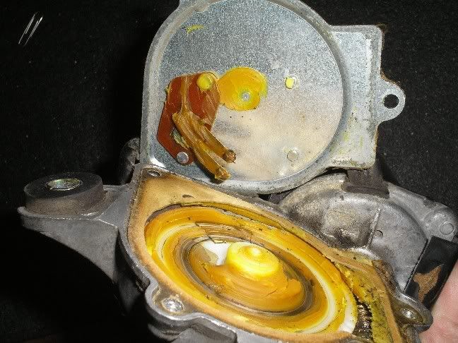
Here are some pics of the honda motor park relay:
This is what the relay looks like on the inside.

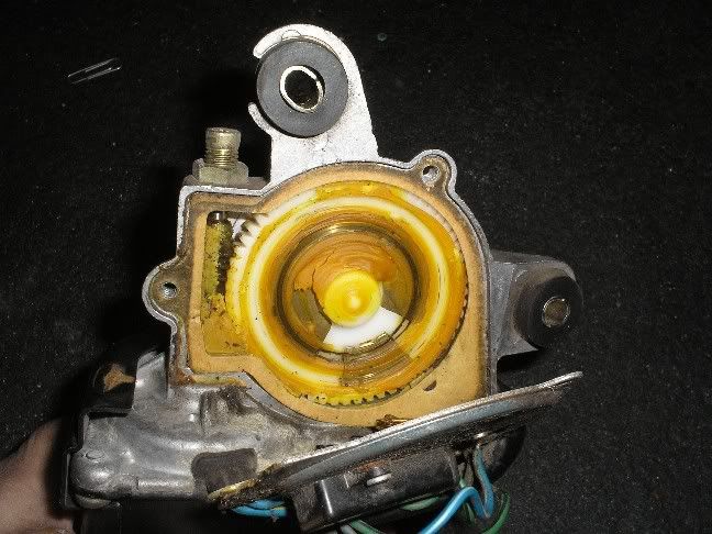
The contacts in the gear.
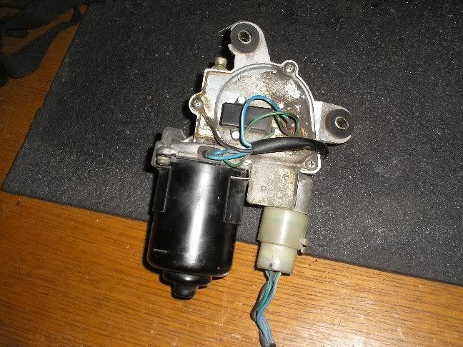
The relay is the black box with the two wires coming out of it (green and green/black).
You can see by the above pictures that there are contacts that are made and broken inside by the rotation of the gear past the contacts of the relay, this is what allows the motor to park in the same spot each time.
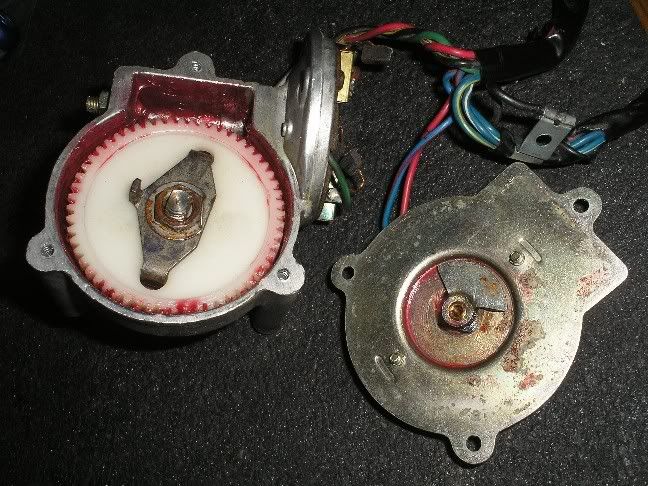
This is the tab and gear on the stock 240Z wiper that actuates its relay.
The following is a quote I took from some information I found while searching the web for answers to this problem we are having.
The theory behind the parking circuit is that when the power is disconnected from the motor it has inertia and continues to spin as it slows down. As the motor slows down it effectively becomes a dynamo generating a voltage in the windings. By shorting the windings the dynamo is being asked to supply a very high current, this places a heavy load on it, this stops the motor very quickly and this achieves a very predictable parking position. The park switch “electricallyâ€, remains in the PARK position for only 10% of a revolution and in the RUN position for remaining 90%.Dragonfly
-
Your welcome. Did you get the steering column switch assembly while you were at it? If not it could be a good idea (or at least take a look at it) because the contacts do start to get a little rough after awhile.
Dragonfly
-
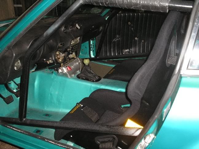
I guess I'll post this here as well.
I just recieved a OMP ECO seat (paided about 300 for it). I bought it because it was the most narrow at the "wings" compared to the other seats from Momo (start) and Sparco (sprint). The ECO was supposed to be 19.7 wide, BUT when I recieved it, it measured 21.25" makeing it wider than the other seats i was considering. Anyone else have experience with this seat or the Momo start seat or the Sparco sprint seat? I want to get the most narrow race seat I can to avoid hitting the doors and also to avoid that love seat look in the car...
I have the MOMO Cup GT seat in my Z, it measures 23" across the wings and does not hit my door at all. One thing about my mounting that may be different from the rest of you is that my seats are hard mounted into the car with no sliders. Fortunately there is a store that is local to me that has most of the popular race and after market seats in it with at least one of each seat in stock on display for you to sit in. I was able to sit in most every seat I have seen people talk about on HybridZ and I was planning on buying the MOMO Start seat, after sitting in dozens of seats I chose the MOMO Cup GT seats as the most comfortable (for the price) and the fact that they are FIA certified and have removable cushions for easy cleaning or replacement.
Here's a quick shot of them.
Dragonfy
-
I learned a long time ago not to trust my memory to much when it comes to reassembling something that seems obvious, In the future mark everything with as much detail as possible and take digital pictures as you go. I'm not sure how much help I will be able to give you on the radio but I will look at my diagrams after I get home.
The rear defrost on Z cars usualy does not work because the element in the glass has been worn through by age and cleaning and therefore has opens in the circuit (usualy several of them). There are kits you can purchase that allow you to rebuild the "trace" in your window, it might be a good idea for you to research that route.
Dragonfly
-
Rather than trying to explain the diagrams I just converted them so I can post them.
This one is from the diagram for the 74'
And this one is the diagram for the 77'
Hope these help.
Dragonfly
-
Dragonfly,
Thanks for your help so far!
Does you diagram show which connections on the relay are used? I am going to start calling the J/Ys, but I think it is unlikely that I will find one around here.
Diagramaiticaly it does but I will have to wait untill I get a chance tonight to get a look at it again. I will see if I can tell you which wire goes to which pin in the picture you have.
I have spent countless hours going throught the wiring on the Z cars I have owned so I know the frustration.
Dragonfly
-
update: I seem to have some connection issues, because while troobleshooting my turn signals not working I now have slow and fast wiper speed, intermittent (it only cycles once though), and the wipers cycle once when turned off and then return home. This is a definite improvement, but I still need to get the intermittent to work correctly.
If you go to a salvage yard like I mentioned in the post above get the entire steering wheel switch assembly while you are there. That assembly consist of the headlight switch, wiper switch and blinker switch on the opposite side. Before you get this replacement pull yours out of your car and look at the connectors on it and make a note of them, take your note with you because not all these switch assemblies have the same connectors and you want to be sure the replacement one you get has the right ones for your car.
Dragonfly
-
My diagram shows two connectors to the relay, one connector with three wires (which I see in the first picture) the second connector with four wires. I can see from the pictures that some one in that cars past thought they knew more than the manufacturer and cut off the connector than (probably much later) fastened some replacement wires on it to try to get it working again.
At this point I would recomend that you try to find a 73' thru 76' Z in a wrecking yard that has that relay and the proper factory conectors, buy the relay and the connector you are missing (with about 4" of wire). Then splice the connector back into your wiring harness making sure your wire colors match up, if your old relay is toast from abuse you have a replacement for it in your hand. Oh yeah I almost forgot to say that my diagram showed some blanked off pins on the relay.
Dragonfly
-
Since she is obviously challenging the man laws I think you have the right to inform her that she must actually do it herself and use her own tools when she needs something done and also she is not allowed to use any of your tools. Of course you will uphold your end by not using any of her tools.
Dragonfly
-
I just took a look at some of my wiring diagrams and what I found is that there is a relay but my drawings show it as having a blue wire with a yellow stripe, a blue wire with a red stripe, a yellow wire and a black wire. If you have the ability to open an AutoCAD drawing I will send you the wiring diagram.
The diagram I found it on was for a 74' 260Z, when I looked at my diagram for a 72' 240Z it did not have this relay, I do not have a diagram for a 73' 240Z so I am guessing that you have a late 73' that has many of the 74' goodies in it.
Dragonfly
-
What's a Motorsport?
West Coast Nationals http://www.thezstore.com/page/TZS/CTGY/WCN of course this link is to the 2007 show and the one I am thinking of was a number of years ago.
Dragonfly
-
Actually, I'm thinking of not using reflectors at all, since I'm planning to make
some pretty little circuit boards - and pumping 'em full of LED(s)!
I dunno, guess you could coat the circuit board with some aluminium foil or something.
I'll make some prototypes when the time for the electrical comes.
I run LED's for all my tail lights except the brake lights. The LED's are bright but because they have such a focused beam they do not disperse light that well. I use mine the way I do because I know people can see the LED's just fine at night and when I hit my brakes the incandescents come on like flood lights to wake up the person behind me.
As for the foil around the LED's that is actualy a good idea, what works best is to have the reflective material completely flat and about two times the width of the LED down from the tip, then at the edges of each LED grouping raise the reflective material up at about an 80 deg angle away from the LED's to a height of either two times the hieght of the LED above the reflecteve material or to the lens depending on your design. If you are inclined to do so (and since you are making your own LED boards) you can angle some of the LED's at 45 deg and some at 90 deg from the primary LED's then use a standard reflector to amplify the light from the angled LED's.
Dragonfly
-
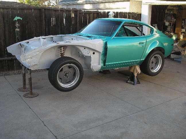
That's what the PO said it was. I got my car in 2001. Maybe I could pick up some for touchups, but the painter had a hell of a time matching the paint to my car last summer.
my color:
thxZ
Hey... thats not the Tomohawk... It seems to me like you showed the Tomohawk at Motorsport a few years ago, wasn't it that really great looking blue one that I may have accidently drooled on? Oh yeah anyway that paint has a very fine metal flake in it which does make it a little more difficult to match but unless you are going for trophies with the car you should be able to get a paint shop to mix some up for you that will only be noticed by you or a concourse judge.
As for the drain/vent thing IMHO what you are talking about doing is a lot of work for a very minimal gain. I personaly think that if you really want to have functional side vents you would be far ahead to punch/cut/drill holes in the sides rather than using that fairly small for the job drain hole.
Dragonfly
-
Looks to me like you will be charting new teritory with this... Just make sure you have good grounds for the tail light harness so you get the full power to the bulbs, the more layers of color you have to go through the less light there is for the person behind you to see. As a side note (and you are probably planning this already) make sure to fully polish or replace the reflectors in the tail light housings as well as clean and polish the lenses. On our cars they are still made out of a polished piece of metal rather than a chromed piece of plastic so they tend to corrode/rust and loose thier ability to reflect light as well as they used to.
Dragonfly
-
Dragonfly,
You can see that rubber elbow for the drains up under the dash on each side.
Some people have been upgrading the cowl drains by gluing in a 45-degree PVC elbow, then a length of big flexible tubing behind the fender to the underside of the car.
I would be carefull about doing that, the tube is the primary restriction for leaves etc. and if you add more tubing you are increasing the potential for needing a drain snake to clean out any clogs.
I thought that you could just go straight from the drain hole through the floor, but I wonder if pressure from below would blow air up through the cowl, which would be a problem ( moisture into the heater & interior.)I think that the pressure in the cowl would be higher than the pressure under the car but you would probably loose some of the positive airflow through the drains that help keep the water out and helps push out smaller obstructions.
Anyway... do you think you could hammer the corner of the tub below the cowl drain to help air flow directly from the wheel well to the vent? It would make the fender vents on my GTO body functional.You could do that but I would not recomend it, by doing that you loose the functionality of the drain (which works for both rain and washing the car, also see my comment above about draining under the car). You would also still have a fairly small hole in which air could flow out of the engine compartment to the fender vent. Also the beating applied to the corner of the tub is going to look much worse than the holes you could drill like mine or many of the others on here have done.
I love your paint colour! Mine is the same colour, but the PO was cheap, and the paint wasn't so shiny. What colour or number is it?thxZ
The paint is a stock 1991 corvette color, I don't recall the number but it is a base/clear coat type of paint but I believe it is called "Teal Green".
Dragonfly
-
I will try plugging the wires into the relay one at a time and see what works, but I don't want to kill the relay or motor.
I doubt if you will kill the relay or motor but here is a suggestion for you. Use your multimeter (or borrow one if you don't have one) to check each of the wires. Set the meter to read DC volts then connect the black wire from the multimeter to a good ground, with the key turned to the run position check each wire with your red meter wire, write down what each wire reads. Now turn your windshield wipers to low and check each of the wires again and again write down the readings for each wire, repeat again with the wipers on high and intermitant.
If these wires and that relay are for the wiper motor you will have one wire that had 0 volts with the key on and the wiper switch off and 12 volts (+ or - 2 volts) when the wiper switch is turned on, you should have one that has 12 volts (+ or - 2 volts) all the time, one wire that goes to ground and one wire that seems to do nothing.
If you find the above to be true then the wire that had 0 volts with the key on and the wiper switch off and 12 volts (+ or - 2 volts) when the wiper switch is turned on is your power wire for your relay, the grounded wire is the ground wire for the relay (should be black), the wire that has 12 volts (+ or - 2 volts) all the time will be the power for your wiper motor (at the relay) and the one that seems to do nothing will go to your wiper motor.
Unfortunately from the wire colors you said you have I doubt you will get what you are hoping for. If you can try to get a picture of the relay and the wires and post it up, if I can't tell where the relay is from the picture give a detailed discription of where it is mounted as well.
Dragonfly
-
he uses that fat girl to keep from getting hit by rocks and stuff off the highway
Its not very often that I truly lol but you got me with that one.
Dragonfly
-
With your car being a 73' I could be wrong on this but I believe that your car only has "off", "slow" and "fast" for the wipers, as for the wipers not returning to the park position that has to do with your wiper motor not a relay under the dash. Unless you feel like a little torture and getting the oportunity to shed some blood, sweat and tears (as well as curse words) on the car just practice turning off the key when the wipers are where you want them. You can also do a search for using the Honda wiper motor for your Z...
Dragonfly
-
So after looking at this picture again I have to ask... How much water does the spare tire well hold? If you pull that rubber plug out it will let the water drain out, and I would leave the rubber plug out until I fixed where the water is coming in from. Standing water is a great breeding ground for both rust and misquitos.
Dragonfly
-
I just noticed this in some old photos. My car has a hole and tube in the inner fender that looks like it vents air. Not sure if Ill make it bigger but atleast they (datsun) knew what the problem was.
Got my pin in hand and getting ready to burst your bubble... What your seeing in the picture you have there is the water drain for your cowl, you have one on each side and the rubber tube actualy runs inside the car. It connects to the bottom of the cowl just inside the firewall then runs through a hole (with a grommet on it) to the outside but inside the fender. This is the hole that gets filled up with leaves and crud then does not let water drain from the cowl and causes some of the rust that our cars are known for.
You can see the hole fairly clearly in this shot and you can tell it is aft of the firewall (and aft of the holes I drilled for venting).
Dragonfly
-
Ahh theres nothing like finding all the latest gremlins that youv'e installed, its also quite amazing how they can tell when your pride or ego has reached the ideal point for instant deflation. I won't even go into any of my gremlin stories (spent to much time trying to block them out of my memory). But my been there done that story was driving an RV through a busy intersection (making a left turn) right in the middle of the intersection the engine blew and locked up, and dumped oil etc...
Good luck on chasing away the gremlins and remember always make sure you give rides to fellow gear heads so you know they understand exactly what your going through when a gremlin strikes while showing off.
Dragonfly
-
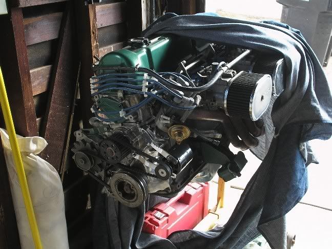
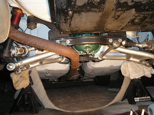
I am only answering your question about your headers. I don't have a straight on picture so I will post two pictures...
Does that look familiar? Well it should it is the exact same header you have in your picture but without the "Y" addapter welded on. The header is (or was) sold by Motorsport as a non smog (no air tubes) 3 into 2 into 1 header with a mandrel bent 2.5" exhaust and a turbo muffler.
It is a little rusty now but I bought this kit brand new back in 1991. The kit was designed so that each piece slipped together, appearantly with yours someone was having a problem with the "Y" addapter coming loose so they decided to have it welded, it also looks like they removed the mandrel bent 2.5" exhaust for a crush bent one.
Any way after all the above chatter what it comes down to is that unless you know that the engine has a cam in it that will benifit from the header your better off just going with a stock exhaust manifold.
Dragonfly
-
I would say to check with Modern Motorsport but I believe all his springs are for coil overs. You can also get coil over kits from MM or Ground Control (and even AZC) without the camber kits for much less than $1600.
Dragonfly
-
I might just be thinking negative here but to me it sounds a lot like the rear differential "death knock" which is caused by the shaft in the carrier coming loose and wallowing out the hole (it sits in) in the carrier. All three of my diffs that died from this ailment started out making a knocking sound when putting the car into reverse, then when backing up and finaly under deceleration.
This could be a good time for you to go ahead and drain the rear diff, pop the cover off and take a look at things on the inside, if all is healthy put some new gear oil in and start hunting for something much less major. Good luck on this one.
Take a look at Jons sticky on differentials to learn more of what I am talking about.
Dragonfly


Improving the wiper motor
in Miscellaneous Tech
Posted
I almost forgot to add these to this thread...
The above are from the FSM for a 74' 260Z. I do have some additional information but I am not posting it up here at this time to avoid confusion. After I have a chance to work the whole thing out and give a difinitive step by step I will post everything up, or anyone who would like to beat me to it (which would not be hard to do as it will probably be a couple of weeks before I can actualy start on it) can send me a PM asking for the info and I will PM it to you.
Dragonfly