
Derek
-
Posts
1317 -
Joined
-
Last visited
-
Days Won
40
Content Type
Profiles
Forums
Blogs
Events
Gallery
Downloads
Store
Posts posted by Derek
-
-
Hi Phar
2 hours ago, Pharaohabq said:and what did I find? THIS!
Took you long enough:)
2 hours ago, Pharaohabq said:The 3D sand printing is intriguing, and seems to have great resolution
It truly is an amazing process. It opens up so many things to be produced that would not have been practical before.
2 hours ago, Pharaohabq said:Question though, How did you figure the cam profile for 6 cylinders vs the Honda 4cy? Is it based on any existing L6 cam, or fully custom, derived from L28 cams?
The profile that I machine into the cams are oversized based on a Schneider profile. At that point any cam grinder with a Honda profile can finish them off. The lobe is large enough for most builds. It's S7 which means it's through hardened so you are not restricted by case thickness.
2 hours ago, Pharaohabq said:I will keep watching this thread and lurk your Datsunworks site
Yea the VCT should be pretty interesting. I'm starting a pool for how many valves I bend before I get it all sorted:)
-
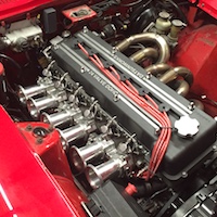
VCT Progress!
So slowly but surely I have been chipping away at making the VCT fit in the available space. What a freaking PIA. The problem with timing chains is you are constrained distance wise by the pitch of the chain and the adjustment can be a bit coarse. Multiply that by two and you can see how it can get tricky. I model things the best I can in 3D but when it comes to something like this I find a hands on approach leads to a more satisfactory result.
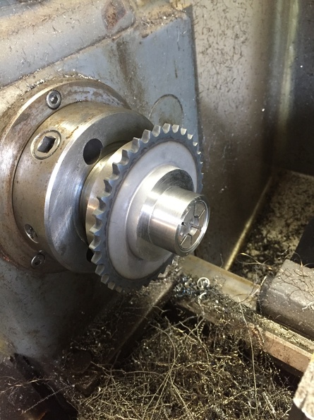
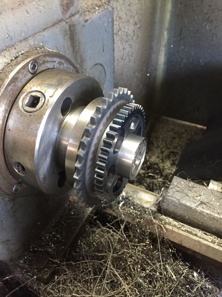
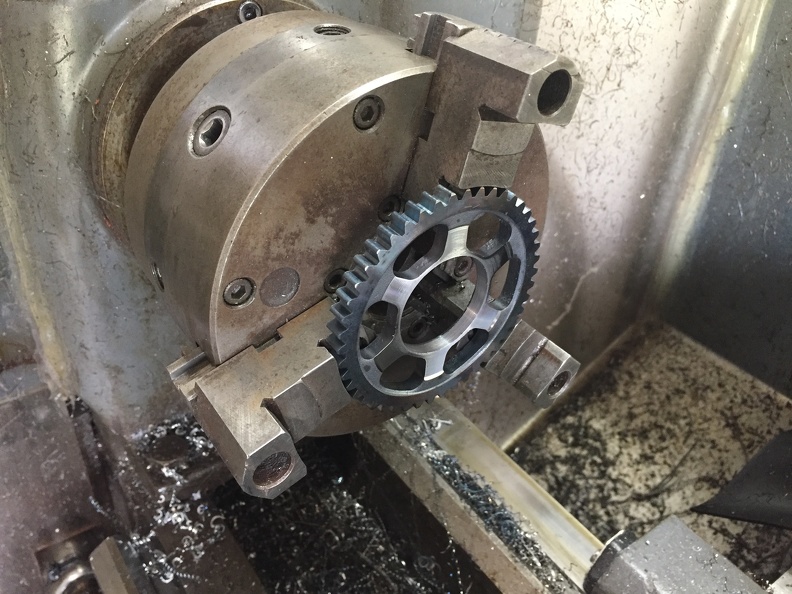
Machined of the small gear from the KA24 idler.

I'm using a 5C expanding mandrel that I machined to fit.
Test fitting the Honda exhaust cam gear that I machined previously.
Happy with the fit for sure.
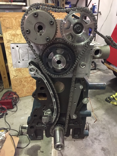
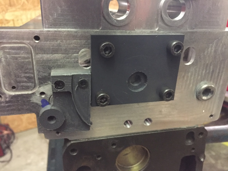
Quick test fit with the first idler sub plate. Looks good but I know from experience that there is a really long road from this point to the final fitting.
Here are the finalish mockup sub plates for the idler gear and the tensioner arm pivot. I may move the idler up another .010" but I haven't decided.
I do the majority of my prototyping in plastic. Easier to work with than aluminum and a lot cheaper. The idler plate will be steel and the pivot plate will be aluminum.
Upper tensioner mount.
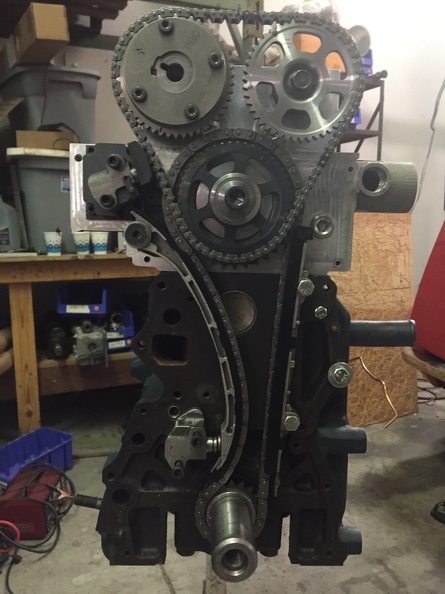
The semi finished layout.
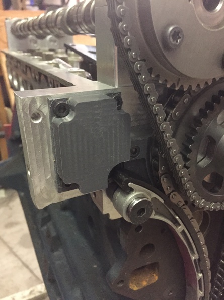
Upper tensioner is from a Mazda 626. Hybridz member Tioga turned me on to this one . I reshaped the contact shoe a bit and slapped it on there. It is a ratcheting style. They can be problematic if the lobe design on the cams are crappy. The constant pumping on the chain can break the pawls. I'm making the assumption at this point the Schneiders lobe design is a lot better than Cranes and won't be a problem. I had to reshape the contact shoe and will probably work it some more if I stick with it.
Tight fit but the bottom line is....It fits. Which is a good thing since I committed to the cams before I knew for sure. Unfortunately I can't access the VCT oil ports on the head because the idler gear is covering them but I already designed a manifold as a work around.
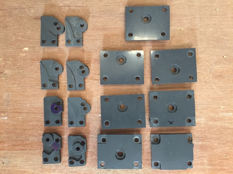
So if the pictures make it look like this was a walk in the park here is a shot of the different versions of the sub plates I made to get the relationship between all those moving components the way I wanted them as well as fitting in the space I had to work with.
I picked the wrong time to quit sniffing glue:)
-
Episode 17 dropped.
-
6 hours ago, turbogrill said:
happy to stress it for him
I already have all the stress I can take right now. Thanks anyway:)
-
-
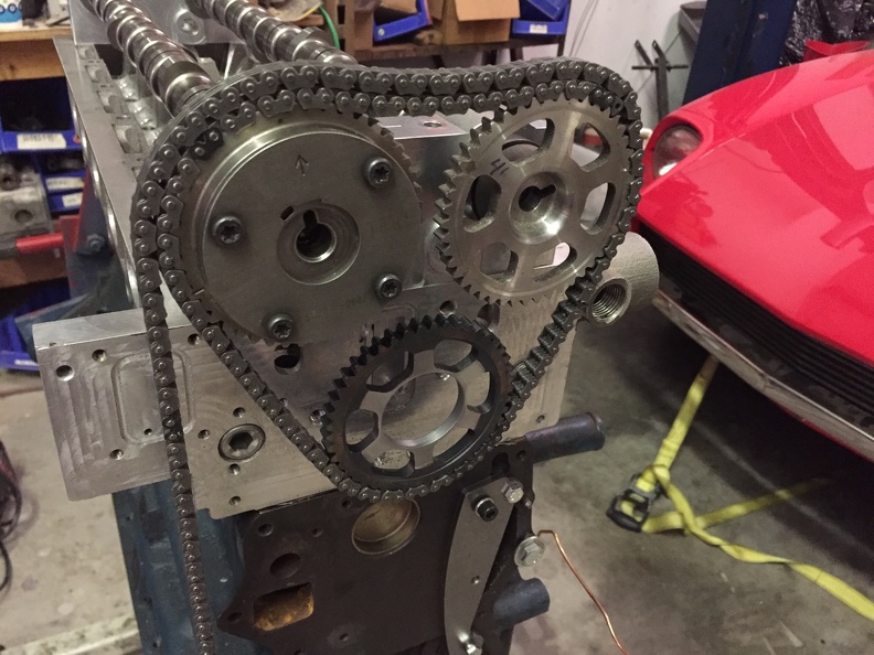
Got the VTC cams back from Schneider so I was able to mess around a bit wit the upper chain.
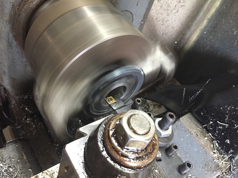
Machining the center out of a stock Honda exhaust gear. Holy bajezas was that thing hard. I had to anneal the center to make any headway through it. Came out great though.
Action shot.
Looks promising but there is a lot left to do.
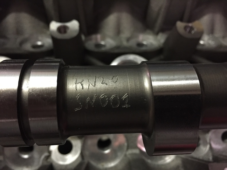
Best part is my stuff is always S/N001
-
 1
1
-
-
That damper is different than the ones I have. Also the rubber on yours is looking pretty tired. I'd keep a close eye on it. The good news is with the trigger wheel bolted on at least it won't fly through the radiator when it lets go:)
Glad to hear you got it sorted out.
-
For whatever reason, the dampers I've worked with are 1/4-20 imperial. The only thing I can think of since the pulleys were US dealer add on they specked out imperial.
-
Those are designed to keep rocks out of race motors that will be rebuilt every couple a seasons:) I use oiled foam in mine. I figure the HP loss is probably equal to the permanent HP loss from scored cylinders.
-
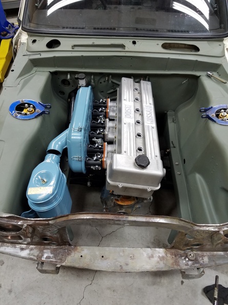
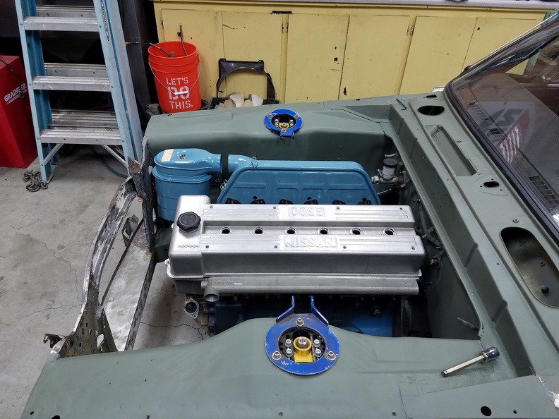
Owner of V3 sent me an update picture.
Pretty freaking cool if you ask me.
I checked the 3D model and tilted the amount they did the intake side of the water jacket is just below the outlet so hopefully there won't be any steam pocket issues.
Snifff....I'm so proud:)
-
1
-
-
Hi Nigel. Good catch. Yes for sure. As soon as I saw what was going on I plotted out the valve cover o-ring tool path and the .125" o-ring runs right across it. The valve cover fits on the mount bolts really well so there won't be any shift. I really really really hate welding on the castings after they have been impregnated so I opted to go another way. If it doesn't seal an epoxy repair up in that corner will work fine.
This is always the toughest part. Making the compromises.
-
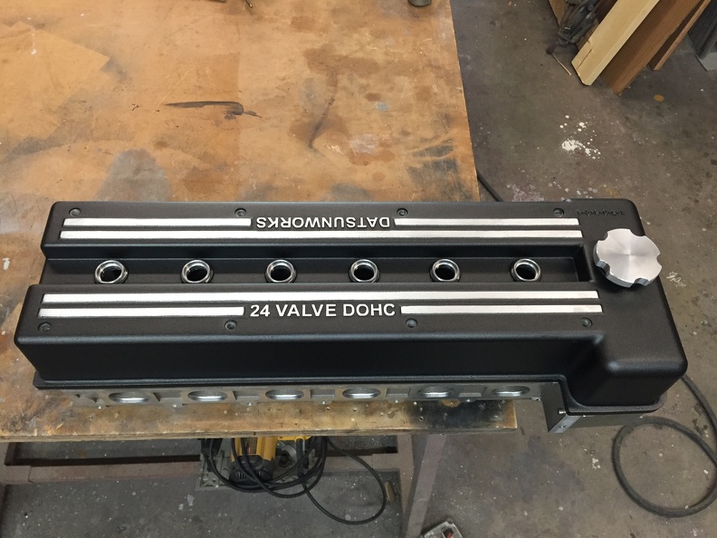
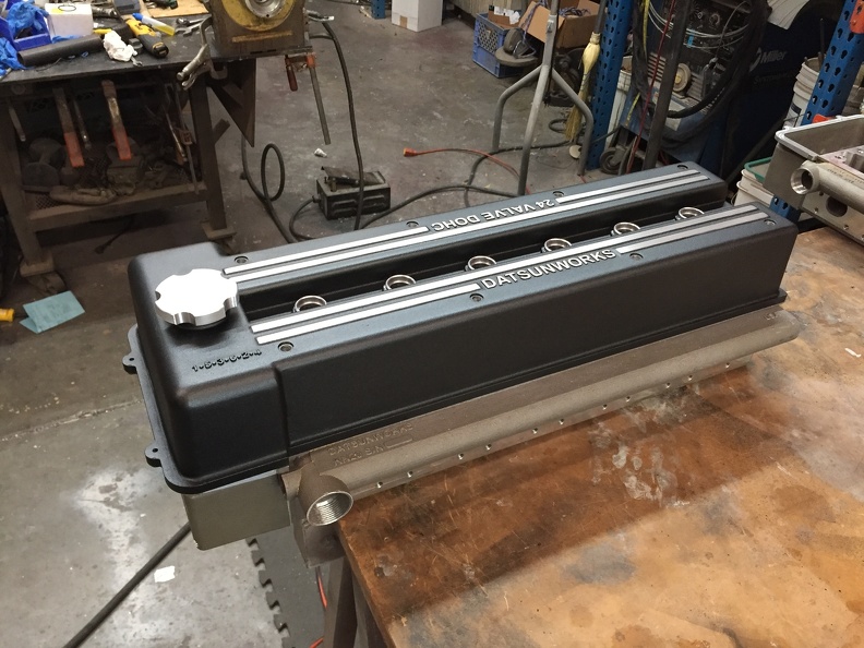
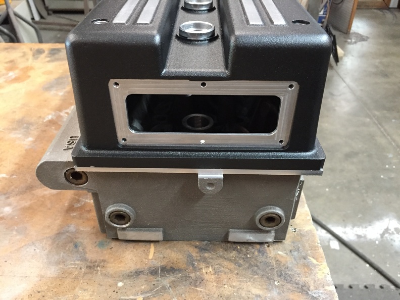
Valve cover powder coated.
I had powder-coated.com do the powder coating on my new valve cover. Same color as V1. Excellent quality as usual.
I’m a bit away from needing a finished valve cover but never underestimate the value in having it for motivation:)
So this is the big change I made to mine. This is to hold a mounting plate for the VCT sensor. Since it requires a special setup on the millI I only plan on making this mod on VCT specific builds or on special requests.
-
1 hour ago, Ineptitude01 said:
isn't really a 'standard' or 'turnkey' config.
I'm not sure there will ever be a turn key solution. In some ways this is a real plus because you end up with a head and valve train that is tailored to your goals. Hopefully a few other builders other than Rebello will jump in and then there will be more choices. I think it's appealing to Rebello because getting an L6 head to flow enough volume to support a 3.5L can be challenging.
The owner of V2 has a 3.0L and his requirements are a lot different. From a production standpoint I've made all the changes to the head that I plan to make so the next batch should go a lot smoother. Hopefully these four will move quickly so I can get busy on the next batch. Rebellos firm on two heads and possibly a third.
All five casting passed the final pressure test at 75PSI and that is the point at which I can start relaxing a bit. I still have to sweat out the finishing of the cams and hopefully at that point I'll sleep a little better:)
VCT cams should be in my hands next week so I'll be able to start mocking up the gears and chains. Fun fun fun!
Derek
-
7 hours ago, Ineptitude01 said:
Reading this thread finally pushed me into getting another S30 shell. It doesn't have an engine, so... Obviously I should RB swap, right?
Where is the fun in that:)
-
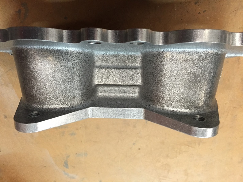
V3 manifolds finished
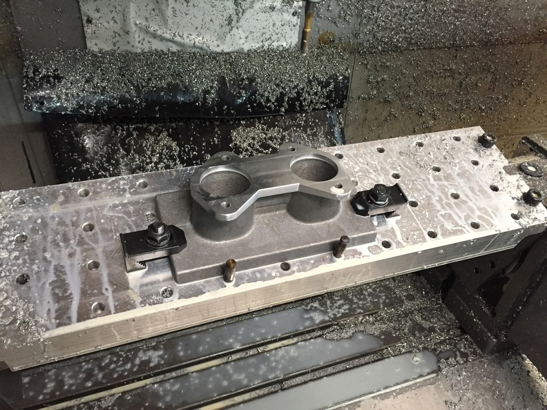
Finished up the manifolds for V3. These were tricky because the owner of V3 decided to
make my life miserabletilt the motor the opposite direction. He did this for looks plus he wanted to gain some distance for his induction system. I did a quick check on the 3D model and it looked doable.Trunnion plate on the 4th axis comes in handy for this kind of stuff. DCOE pattern matched to 48mm.
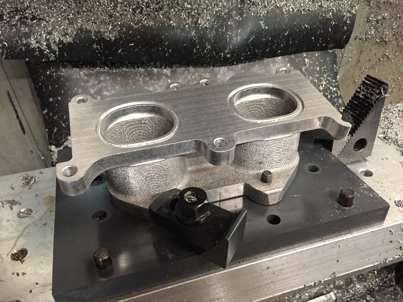
Made a quick fixture/index plate to locate off of the DCOE flange. I find most people prefer that their carbs/ITBs line up when they are bolted to the manifold:) Port matched to the head and o-ringed. Rebello will blend the port match into the manifold. Since every build is different I figured the best way to handle it is to cast it a little smaller and then blend as necessary. The ripple pattern you see is from the 3D printed sand. There are certain angles where the layers on 3D printed items are fairly pronounced. I was surprised how well everything worked considering the manifold casting is 180 degrees out from it’s intended angle.
I kind of cheated this shot. The manifold has already been through the vibratory finisher so this is the final finish. I threw it back in the fixture to get the picture.
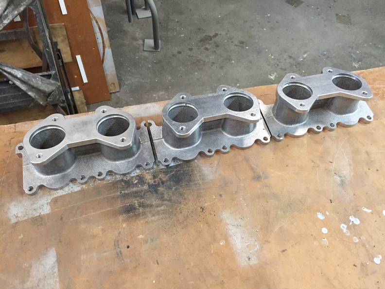
All done and looking pretty!
Added a rib in the center so that if people have drop link type linkage they can mount the risers to it.
Manifold looks a little fugly in this shot but it really isn’t:) This is the last of the V3 stuff so Rebello should be good to go at this point.
-
I'm thinking electric at this point:)
-
Quote
Derek, Maybe you could whip us up a few heads with both in your spare time.
Hold my beer.
-
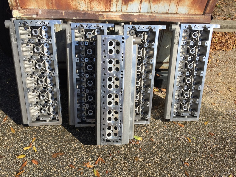
Machine work finished!
I can relax a little:)
Just got done with their first bath. Still need de-buring and edge finishing but the majority of the work is done.
The VCT holes are drilled and tapped but they haven’t been drilled all the way through. Easily opened up with a drill if needed. The head has provisions for three sub plates. Timing chain idler, upper tensioner and a slack side guide pivot. The idler and tensioner are connected to the oil system and o-ringed. It is getting really crowded in there with all the oil passages, head bolts and cam tower bolts.
Next stop vacuum resin impregnation.
-
2
-
-
3 hours ago, Tony D said:
Derek,
Is the valve cover O-Ring Groove square or trapezoid?
Our gearboxes use a trapezoid cut o-ring groove on the splitline. We can do that easily because the cutter can enter from multiple points around it...you would have to plunge in and go...
That trapezoid holds that O-Ring in place so you really don't have to glue it except around 25mm at each endpoint where oil can enter from the gearbox. I would assume with this one you could either superglue the O-Ring stock and then put it in place or maybe butt the ends and apply a dab of Loctite 598 / Permatex Ultrablack to seal the oil intrusion point.
It makes it kind of nice as you lift the cover off and the O-Ring is held fast and doesn't fall all over stuff.So here is what I ended up with the o-ring so far. I made the groove tighter than I normally would for a pressure seal. This way the o-ring stays in the groove well enough to handle without it falling out. For those of you that don't know o-ring grooves are wider than the o-ring to give the seal a place to go as it crushes. The valve cover isn't exactly a high pressure seal and the method of attachment doesn't have enough oomph to pull the seal down evenly. I started out with round but it seemed like it wasn’t providing enough contact area based on the mount of torque I could apply to the valve cover. I ran a square for a bit before the head shit the bed but I’m not sure if it was better or worse. My gut feeling is better because I really increased the contact area with the square profile. Makes sense in theoryville, the land of my people.
-
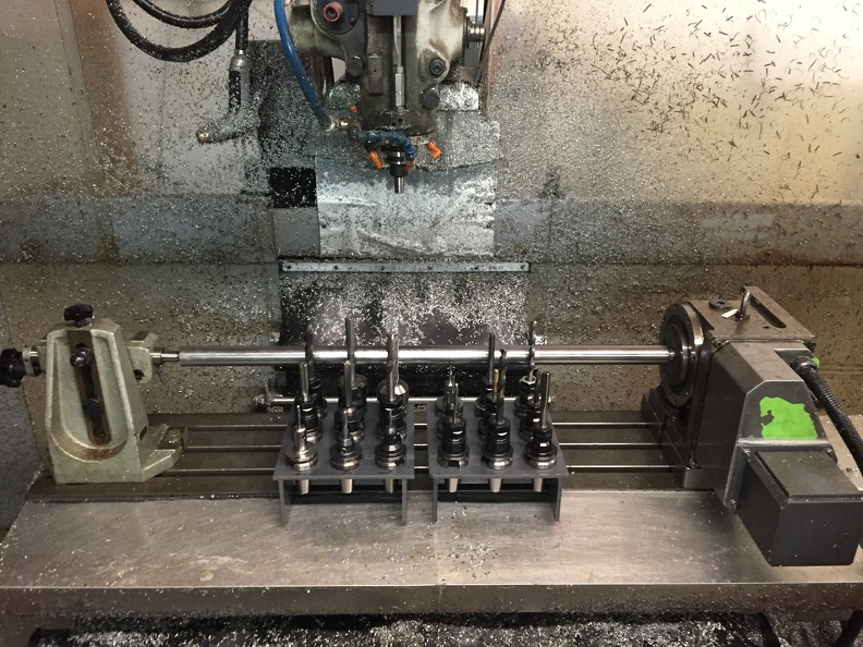
Ready for battle!
Getting geared up to start machining the heads. Officially the first production run.
-
2
-
-
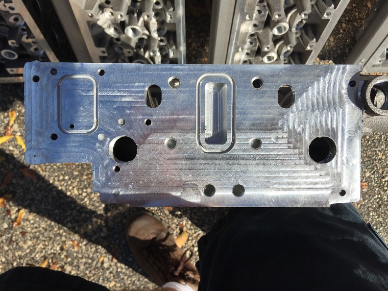
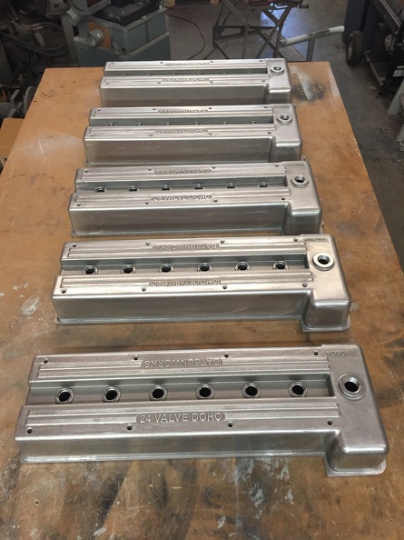
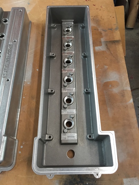
Got the valve covers done.
They are machined and somewhat finished. I've decided that since I don't know what people plan to do for finishing that I would leave the final cleanup to them or their powder coater. I sanded down all of the sand tears, Rand a DA over most of it and then ran them in the vibratory finisher.
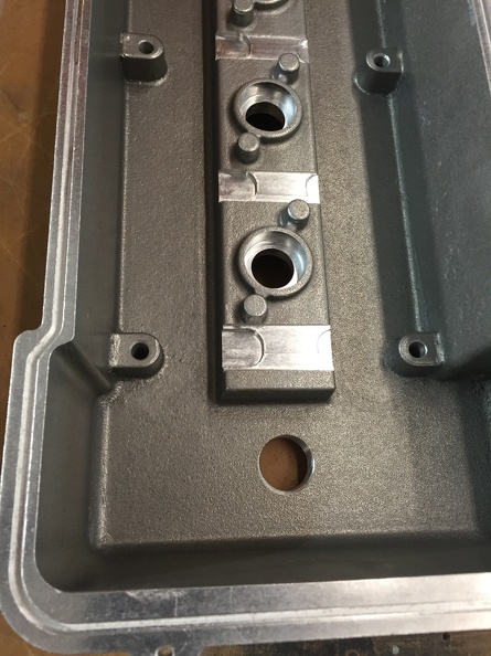
The flange is grooved for a .125" o-ring. I also machine in clearance for the cam towers and bolts.
There are 2 bosses on either side of the plug hole. This is for a KN20 COP. The bosses are positioned so that you can have the plug facing forward or backwards. It's up to the end user to drill and tap accordingly.
Semi action shot.
-
After this batch things should start picking up supply wise. All of the things I control move along quite quickly. Every thing else just takes forever.
-
I did what I did because it looked nice:)
Seriously.
-
4 hours ago, Oblithian said:
Given that you need custom manifolds it seems unusual that you would opt for a tower with MPI rather than DI. Either way, I am certain a few hundred people would be interested in buying this, myself included.
Hi.
I don't know what tower with MPI refers to. I mean I probably do but not by that name.
I hope demand is still there when I actually have heads to sell. No mater either way as long as I have one:)


Twin cam head for the L6 from Derek at Datsunworks
in Nissan L6 Forum
Posted · Edited by Derek
The owner of S/N005 sent me this video. Xtreme Cylinder Heads CNC porting.
I have no idea why the video is giant. I uploaded it directly to the post