
Derek
-
Posts
1317 -
Joined
-
Last visited
-
Days Won
40
Content Type
Profiles
Forums
Blogs
Events
Gallery
Downloads
Store
Posts posted by Derek
-
-
Now that I have a design that I like I'm starting the casting process. I've started a new link here: http://forums.hybridz.org/showthread.php?p=763007#post763007
Derek
-
Now that the design stage is done It's time to start the casting process. If you need to come up to speed on this here is the original post. http://forums.hybridz.org/showthread.php?t=121021
I''m going to make a separate pattern for the front manifold and a separate pattern for the rear manifold.
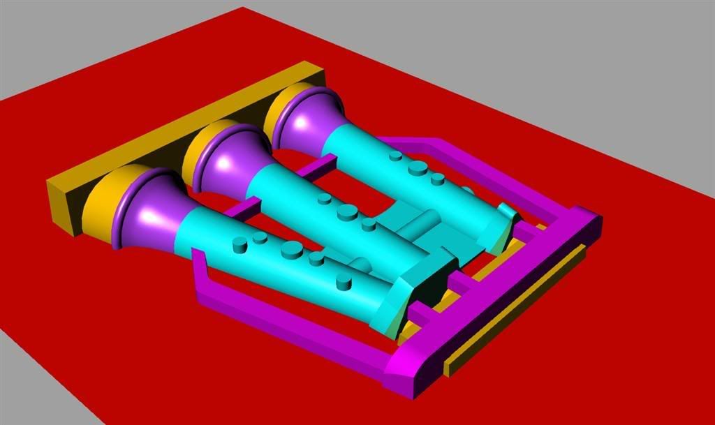
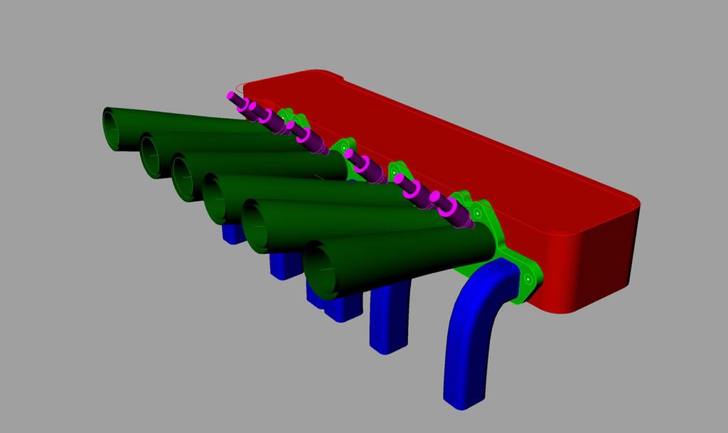
I'll also make a core box for each as well. Here's a picture of the cope (upper) side of the pattern.

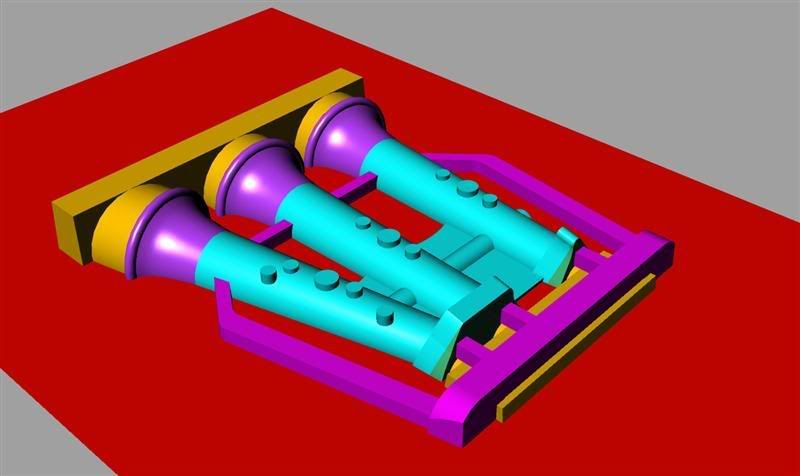
And here's a shot of the drag (lower) side
The gold colored areas are the core prints and cores. Cores are what makes a casting hollow. Prints are what holds the cores in position. The magenta areas are gates and runners. Normally I try to put these in the drag portion of the mold but because of the orientation of the part I need to have them in the cope. Most foundries like to do their own gating so I'm not sure if this will be the final design. Sometimes you have to pour one to see what you get. The metal will enter in the magenta section just behind the head flange. I'll cut this pattern with a ball end mill so all joints will have a fillet. For that reason I don't take the time to draw them in.
As a side note can any one tell me why I can't post attachments? I've sent several messages through the contact link at the bottom but haven't received a reply.
Thanks
Derek
-
Hahaha! Well No Flipping intended here, just trying to help!
Just do a Search for Clippard Vacuum control Valve and use the 10/32" size as they have the largest port for a small valve, do not want them to look like Poo! They will only add about 200 to 300 Rpm to your idle so you will have to synchro the Blades too!
Kevin
Extrudabody
As far as the air bleed valves go can I put one end of the valve in the bottom of the throttle body in front of the butterfly and run a tube to a fitting behind the butterfly? Or do I need to bleed in air from outside the system.
Thanks
Derek
-
1/2" is Plenty for the Brake booster, but the Each Cylinder has to be fed with Equal length Tubes from the IAC Valve itself, if not you will have the closest cylinder to the IAC Valve pulling the most Idle Air and once again another Balance Issue!
Oh you smart guys that actually want their stuff to perform. Don't you know it's supposed to look cool.
I think what I'll do is hook it up with a “T†fitting in between the two manifolds. And feed it in there. I'll also add a boss to the underside of each throttle body in case I have to go with individual tubes.
Yes but look at how cool they look!!!Another thing you may want to consider is the BellMouth to AirHorn ID Ratio! Most consider it overkill if this is over 1.5 to 1 so a 45mm ITB would only need a 67.5mm Bell mouth!(Don't laugh. You'd be a little rough around the edges If you were under a tarp for the last ten years!)
The large (some might even say cartoonie looking!) bells are going to double as an air cleaner housing.
Internally the #1 and #6 tubes have a slight curve between the butterfly and the port to help even them out.Also the angle at which the ITB Runner hits the Head port! If it can not be straight at least they all need to be the Same Angle, one can't be straight and 1 be angled without having cylinder to cylinder flow issues!Kevin
Extrudabody
The air valves for air bleeds sounds like a great way to go. Do you have a part number handy for the style your using.
Thanks for all your suggestions on this I may sound a little flip but I'm definitely listening!!!!
Derek
-
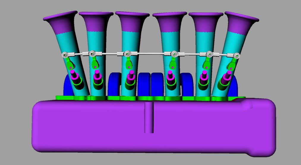
ahh.. I am unsure of whether to even bother posting, I may be opening my mouth just to insert my foot....
...but wouldn't putting the throttle linkage between #3 and #4 balance the load, and ensure that any potential future wear or difference between the butterflies would be more evenly distributed? I would hate to see you have any flex in your throttle shaft that might cause the #1 cylinder to be richer or leaner than your #6, you know? I mean, theoretically, I am right.. but in practice I have NO idea if you would ACTUALLY see the potential issue I mention... just thought I would bring it up, since you asked.
For all practical purposes I agree with you. The complexity of the center linkage is what's pushing me towards driving from the #6 throttle body. For the butterflies I'm using 1/4†stainless shafts mounted between sealed bearings top and bottom. I'm using spherical rod ends for the linkage so there shouldn't be much flex there. I think I'll probably go with this design and put a couple dial indicators on the #1 and #6 shaft arms and check the flex. If there is a noticeable amount then I'll design a system to drive it from the center.
Thanks
Derek
-
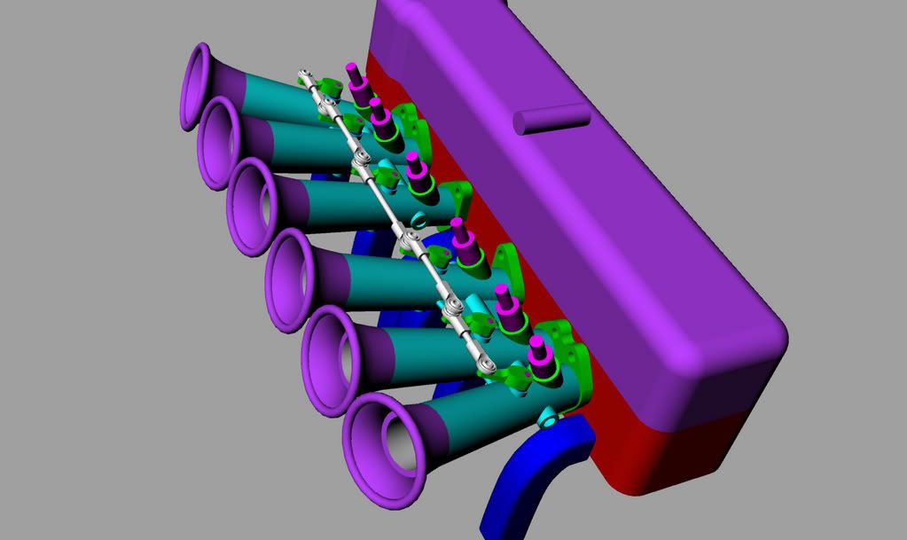
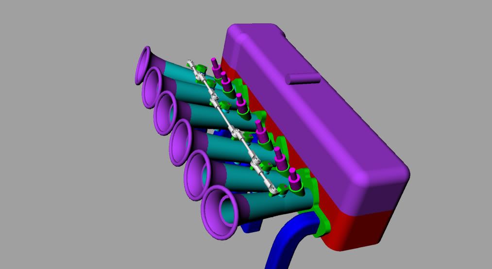
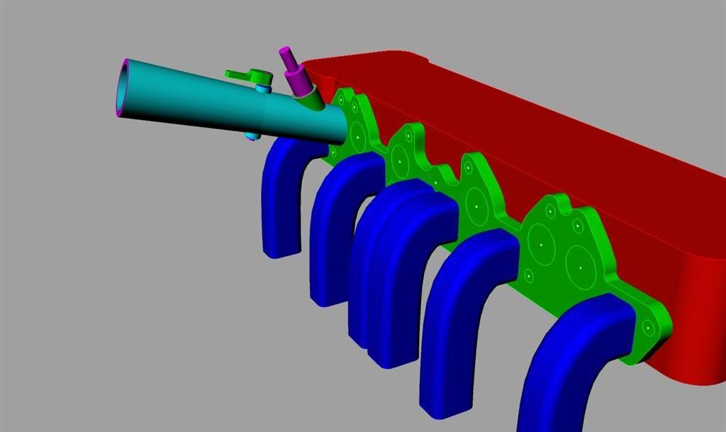
Ok here's the latest changes.
I added webbing with an integral balance/vacuum tube.
The two manifolds will be connected with stainless braid hose. I straightened out the linkages. I added bosses on the bottom for a heat shield. I did away with my construction flange and added the final intake flange. You can't see this but I curved the portion just behind the butterflies on #1 and #6 internally to allow for a smoother transition into the port.
I ordered a set of stock injector hold downs and as soon as they arrive I can model the injector bosses.
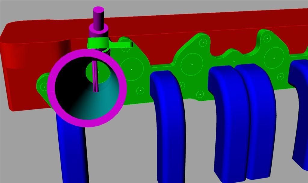
I made the vacuum port 1/2†diameter. Any opinions if this will be large enough for power brakes and an idle valve?
At this point I plan to drive the linkages from the #6 butterfly. Anyone see any problems with that?
I'm going to start making the models into patterns working out the core and parting line issues. I also need to add any first grab flanges for the machining process. I'll post some pics of these as well.
Thanks again
Derek
-
Hi I'm trying to find the bore dimensions on a stock 280 injector hole.
Thanks
Derek
-
So how is the bosch top going to work with your hardline idea? or are you going to run a rail instead?
MSD sells single fittings with a AN flare and groves for a clip. They're $100.00 for a pack of 8 so Iâ€ll probably make up my own. That price is about the tipping point for me making 6 fittings!
Derek
-
Excellent! I cant wait to see it. Are you going to make a few extras or it this going to be one of a kind?
Thanks!
I'll be making the un-machined castings available. I'm not sure if I'll offer the additional parts or not. My CNC Knee mill doesn't have an automatic tool changer so production work is out of the question.
I will supply all of the cad drawings necessary for the parts though.
I'm in contact with Motor Man Fuel Injection Supply about the injectors. Man is that guy easy to deal with. He's making up a set of injectors with the stock 280 base and a Bosch o-ring top. For my application I think this is the best way to go.
Derek
-
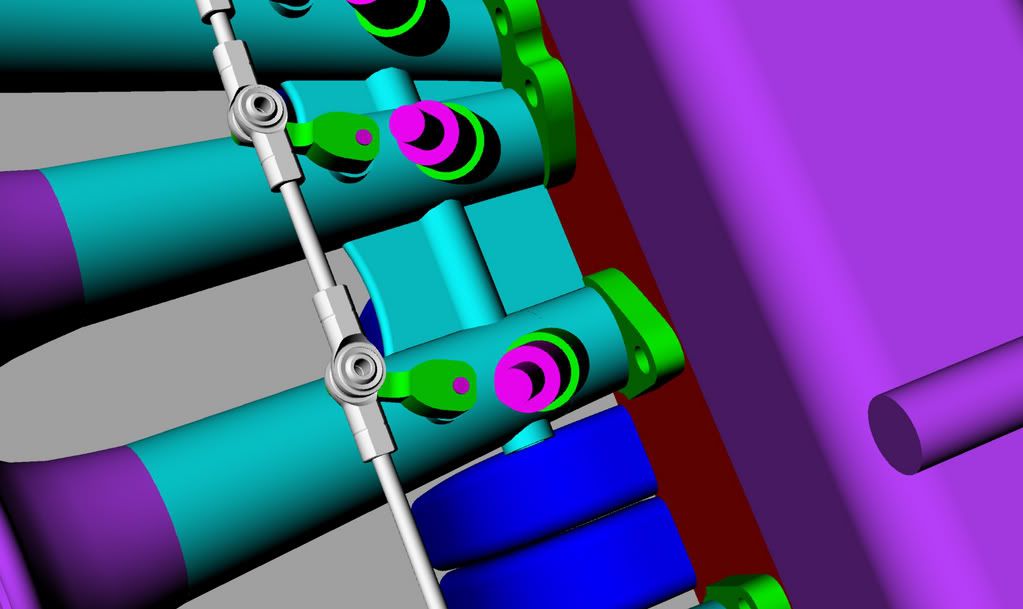
Derek, on your multi colored rendering of your setup you posted...(I believe )you are going to want to have all of the green actuating arms that are connected to the throttle linkage to all be parallel to each other, due to the geometry they are not going to all have the same rate of opening. The arms that are closer to 90deg. angle to the linkage will open more than the ones that are further from 90deg. Does anyone else agree. It's been a VERY long time since 10th grade geometry.
Thanks for the heads up and yes you are correct. If the arms are not parallel they won't open the same.
I threw the linkage in just to give an idea of the direction I'm going. Now that I have the clearance issues solved I'll be redrawing everything including the addition of a balance tube and IAC. Thanks for the info Tony D. Kinsler makes 1.523†diameter throttle plates which will give me their recommended
closed angle of 14 degrees.
I keep vacillating between which injector style to use. Stock 280Z injectors are starting to look pretty attractive because of their clamping system. I could probably machine a fitting to replace the hose at the end so I can still use my hard line idea.
I'm converting a 240 with SU carbs so I'll be using Megasquirt as the control.Will the stock computer work with a custom manifold? Would you have to move to standalone?Thanks again for all the help on this. I'll post a final (I hope) rendering of the manifold in the next few days. I hope to start caving towards the end of next week.
Derek
-
Well if it will fit in the car then I think I'm pretty much happy with this design.
Thanks for the heads up on the hood clearance Dave. I checked the motor and it tilts 12 degrees towards the passengers side. I had enough clearance at 16 degrees but I pulled it down to 14 degrees in case I end up with an air box.
I put a bell shape on the end with a rolled edge. I also added a step for the air filter inserts. The airfilter insert clamp will be designed to help restore the airflow around the step.
I need to do a little research on linkage designs but this is the basic idea. I may try to do a modification to the end arm and drive it with the gas pedal as opposed to a center bell crank. I'm still going to cast it in two banks of three. I'm going to add a little gusset webbing in between each tube for strength.
I've got an injection plumbing question. All the injection set ups I've seen use a fuel rail where the fuel is constantly flowing past the injectors. If I use my single line to each injector with a return at the central block layout will this work? I'm in effect dead ending the fuel at the injector head.
I need to figure out where I'm going to mount the IAT. I'm wondering if I could use a small beaded thermo couple. I could bring it in the bottom of the rear throttle body and epoxy it in place. All I would have sticking into the tube would be a small bead.
Thanks again
Derek
-
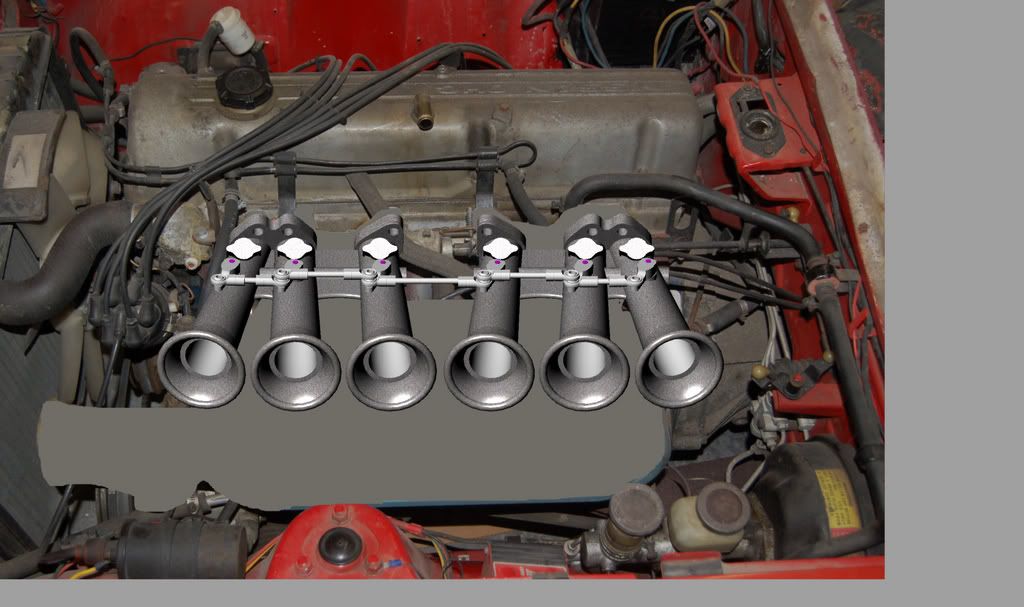
Ok
Here's the latest design.
Overall legnth is 10†which is the distance from the face of the SUs to the head. The downward angle is 16 degrees which lines up pretty well with the port entrance. The individual throttle bodies will be angled in the horizontal plane so that they're all the same length. The bore comes out straight for 3†and then tapers out 2.5 degrees for 7 inches.
Some things I need to finalize.
Injectors. I really don't like the look of fuel rails and they ad a level of complexity on the machining end. I'd love to locate a screw or clamp in style with a threaded top that would accept a banjo style fitting. I could hard line it to a central fuel block with more banjo fittings. I think this would have a very old school mechanical injection look and would satisfy my design criteria #2 “Look Really Cool “
Air filtration. I suppose I could put flanges on the ends of the throttle bodies and use an air box. I'm not too crazy about the looks of an air box and would love some sort of alternative. I could cast a step on the inside of each throttle body and use some sort of mesh-foam-mesh arrangement that would fit inside them. I really don't know how practical this would be. Cleaning air filters every other day might not be very fun.
Linkage. At this stage I'm thinking separate levers and rods connected to a central bell crank and cable driven. I'm also working out the individual idle screw and return spring design.
Here's a cool shot looking down the throat WFO
Thanks for all the help.
Derek
-
Hi
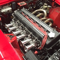
This is my first post here. I have a 73 240 that I've owned for 26 years. It's been in storage for the last 10 and i recently decided to get i on the road again. I'm a CNC pattern maker for the sand casting industry and have my own shop. I decided that I needed to design and cast something cool for the car and thought I'd do something unique like a triple SU set up. Then after digging around a little I see that Z therapy is coming out with one. So much for being unique! After some more digging I came across the Megasquirt site. This seemed to be a lot slicker than three SUs and and being a bit of a geek I love the open source concept of it.
So here's my design criteria:
#1 Look Cool
#2 Look Really Cool
#3 Actually Run
I'm opting for 6 individual throttle bodies in two banks of three. I'm running a stock L28 block with a E88 head. I plan on keeping the throttle bodies fairly long to improve my bottom end. The throttle shafts will be vertical as opposed to horizontal for ease of machining.
Right now I have the the head and exhaust modeled in 3d and I'm starting to do some preliminary design on the throttle bodies.
Here's a few questions.
Is there any benefit to tapering the throttle body. I drew it up going from 2†tapering down to 1.5†because it met design criteria #1 and #2
Is there any reason I shouldn't mount the injector as close to the intake port as possible.
Here's a link to a jpeg of where I'm at right now.
Thanks in advance
Derek
Making my own EFI intake... The casting begins!
in Nissan L6 Forum
Posted
Actually I just looked down at the bottom and it now says "you may post attachments" and it used to say "you may not post attachments" so I'll try to edit the post.
Thanks for making me look!
Derek