dum-bass
-
Posts
124 -
Joined
-
Last visited
Content Type
Profiles
Forums
Blogs
Events
Gallery
Downloads
Store
Everything posted by dum-bass
-

My version of an extended nose front spoiler
dum-bass replied to dum-bass's topic in Body Kits & Paint
I am not in the fiberglass business, just make parts as I need em. I hate mold making with a passion to. -
My version of an extended nose front spoiler
dum-bass replied to dum-bass's topic in Body Kits & Paint
Oh, and yes it is my own mold and handlaid fiberglass. Mold is destroyed but still have the plug that I can mod any way I want. Expensive though!... -
My version of an extended nose front spoiler
dum-bass replied to dum-bass's topic in Body Kits & Paint
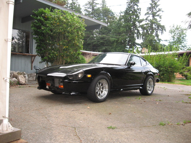
I tend to think it looks better without the headlight lenses but in some respects they still look good. Believe it or not, the frontal open area is still smaller than the stock Datsun frontal area, minus the huge bumper, but my original idea was to divide the air by ducts to the brakes and the intercooler. -
My version of an extended nose front spoiler
dum-bass replied to dum-bass's topic in Body Kits & Paint
Thanx! -
That took you quite sometime to do didn't it?
-
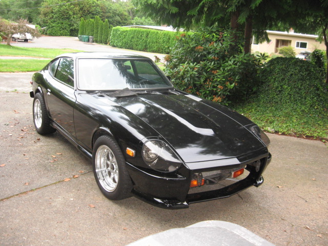
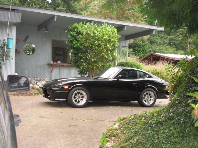
This is it so far, need to come up with a better turn signal scheme and a grill. Sooooo what do ya think? Be honest I can take it...

-
Going to start doin the 1/8 mile drags in monroe this spring, my Chevy muscle car buddy's won't leave me alone about racing my dum-bass. I have had muscle cars in the past and I know my lowly old Ratsun will do just fine! Especially in the 1/8 mile because my car is a rocket ship already! I will post video............
-
Put the tach signal wire between the twisted ends of the diodes and the 1k resister that goes to positive. Do not use the reverse zener diode that the MEGA MANUAL calls for!!
-
So what that means is, pins 10, 11, and 12 of the input plug of the EDIS, you should have one diode going to each one of those pins "3 diodes". Connect the BANDED ends of each one of the diodes "solder them inline on each individual wire" to the inputs of 10, 11, and 12 of the EDIS input. On the other end of the three diodes, twist all three ends together with a 1k ohm resister,then tie the other end of the resister to a 12v switched supply! Should work perfectly!!! ie, This is for the 280 tach.
-
I am sorry guys, I just reviewed some of my earlier posts and discovered that I, Mr dum-bass, posted wrong! Just reverse the polarity of the diodes! Striped end away from the coils. Why? Because a diode is a gate valve. electrons go through one way but not the other way. If you have the striped end of the diode toward the coil, then you are impeding the flow of signal that the tach wants to see! There has been a write up before about this subject that states the opposite, but I believe that was for a 240! BTW don't forget the 1K resister to positive
-
I am going to be famous for this!!! EDIS 280z tach wiring....
-
Just reverse the polarity of the diodes " striped end away from the coil" and yer all GOOD! now tell me if it works!!!!! Don't forget the 1K resitor to positive
-
You guys did not reverse the polarity of the diodes!!!!!
-
So How you guys doin now? My car is doin good so far. First gear? Blisteringly fast!! Second gear? Takes off like a bat outa hell!! Third gear? Keeps up with the turbo's!! Fourth gear? 120mph easy!. Fifth gear? PSSSSSST I am asleap cruisen!!
-
I am happy that you folks actually respond to my thread. My car Rocks!!! and looks goood! luv ya man!!!
-
Anybody ever use a contour guage and compare the left side to the right side of the car while doing body work? How acurate are the metal dies with these old cars? Before, I thought the car looked damn straight and be easy work until I stripped all the paint off and used a contour guage to check straightness from side to side. I am freakin amazed at the differences and I am in bare metal with NO BONDO! So wuddya think? BTW, how is my spelling?
-
 Nevermind. What diff are you selling?
 -
 Yoko, what exactly are you doing with this?
 -
Hey! I'm back! anyone try my method?
-
A couple more things. Go ahead and put that inline resistor, the one under the glove box, back in if youv'e taken it out. Also, the tach wire branches off and goes to the stock transistor ignition box. You should snip the blue wire in the harness connector or just unplug it. My car wouldn't even start with it still connected.
-
I'm having problems with this site today. Anyway, do this. 1.Connect the diodes cathode end (stripe) to the coil wires. 2. twist the diode ends together with the tach wire and a 1K resistor. 3. connect the other end of the 1K resistor to a 12v switched supply. 4. Now go do it and tell me it works!
-
Yes you are right Pete, we have scopes at the shop and still couldn't get anything out of pin 2 (demons) and although your inverter design didn't work for my 280 tach, (more demons) I have still emerged victorious with a completely different diode version on the coils than the megamanual shows. I now have a strong tach signal, car runs great and the thing that baffles me is, why do some methods work for some, but not for others? Different equipment? HEHE!
-
Ok Cygnus, I get absolutely no voltage reference or tach response from pin #2 of the EDIS module. So I acquiesce to the possibility that my car, and everything that I do to modify it, is infested with demons! Even the simplest task turns out to be a time vampire!!! I shall return victorious...
-
The circuit does work, I'm getting a 12v switched signal but apparently it's still not enough juice to trigger my tach even with the inline resistor removed. I'll try bypassing the resistor in the tach itself, I'm fairly confident that will work but what a pain in the a@#!