

Jesse OBrien
-
Posts
664 -
Joined
-
Last visited
-
Days Won
1
Content Type
Profiles
Forums
Blogs
Events
Gallery
Downloads
Store
Posts posted by Jesse OBrien
-
-
Looked around a little bit, found some interesting info on this thread. http://forums.hybridz.org/topic/85340-intake-manifold-porting-and-injector-upgrade/
Also found another good read here. http://www.hotrod.com/pitstop/hrdp_0704_pitstop_fuel_injector_location/
Nice fuel rail by the way.
Really helpful. I hadn't really dug through the archives as hard as I could have, but that's exactly what I would've been looking for. It sounds like it doesn't really matter where my injectors are, so I'm just concerned about getting them to seal.
In the interest of simplifying everything, I'm making a big push to get this manifold wrapped up this week to install next weekend and finally start the thing up.

-
NewZed, it's good to have a little first-hand experience here, rather than just my fumbling around in the dark. I had suspected that this project is a waste of time as far as efficiency/performance, but I'm still pursuing it - if only for parts availability and to finish what I've started.
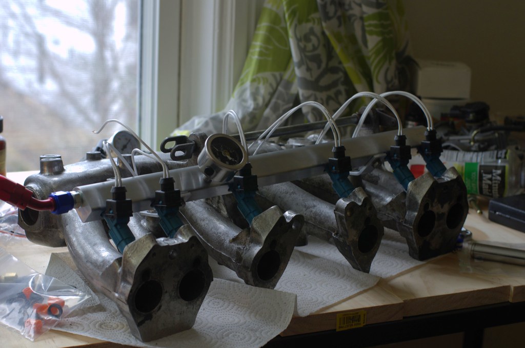
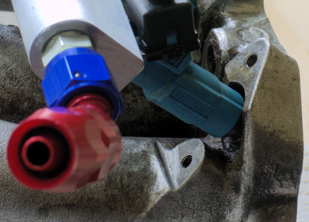
The Pallnet rail came in, and fits beautifully as a mockup.
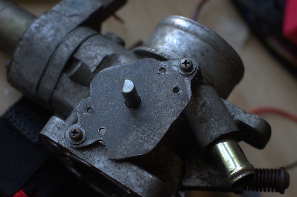
I'm still pretty unhappy with the injector/manifold mating, as the oring doesn't sit IN the intake manifold. I can only imagine this will cause issues for me, especially if I ever want to increase my fuel pressure. I think it should sit roughly 1" deeper in the manifold, and the injector outlet would end up roughly where the stock injector outlet was, relative to the intake valve. You can actually see the oring sitting on top of the intake manifold's injector bung here:
My machinist friend said she'd be happy to enlarge those holes to accommodate the orings, and it feels like the Pallnet rail is designed to have a bit more torque on the brackets. If not, it'd be pretty straightforward to adapt his design to move the rail a little closer to the injector bungs. For better or worse, this plan is coming together nicely.
-
Actually I believe that the bue injectors are 39's and the green tops old style are 42's.
I'm not sure, and don't have access to a flow bench to verify. It may be worth sending them out to get cleaned and tested, but I can't do that right now. My friend said they were 24# when he shipped them to me, but 39# would work great as well. Wikipedia appears to agree with that, but I can't verify that these actually came out of a Cobra Mustang either.
http://en.wikipedia.org/wiki/Ford_Mustang_SVT_Cobra#Engine
First off, I am not trying to discourage out of the box thinking in anyway. I do have a few thoughts and concerns about the spray pattern of your EV1 with single intake valve engine. If you look at the spray pattern of the EV1 (https://www.youtube.com/watch?v=Zu25-ObPUGM) it appears to me that it is designed for a 4 valve head. I understand that the spray is a better atomisation, but does the increase of wall saturation actually decrease efficiency? However, without first hand experience with the injectors, I have no idea if the spray angle would even be great enough to cause the increase in wall saturation or if the injector is mounted close enough to spray at the ideal spot.
Hopefully, someone that has ventured into this territory could give some feedback on this, as I would like to know for myself too.
Thanks for taking the time to post your adventures.
I agree that it appears that way, but the engine these were designed for is a 4.6/5.0 pushrod v8. Again, I'm working on a bunch of assumptions here and won't KNOW anything until I've done some testing. Looking at the spray tests I've seen (like yours, just youtube videos), I don't think it'll be too much of a problem as long as I can get the injectors close enough to the back faces of the valves.
In any event, I have a hard time thinking these will be worse than stock. If they are, I simply keep searching for a better common design.
-
I couldn't find a whole lot of hard info on the EV1 Cobra injectors, so I figured I'd start documenting myself here. Maybe some of you more experienced folk can point out some flaws in this plan that I don't know to look for yet.
Initial Thoughts
I got lucky and scored a set of 24# (~252cc/min) @ 42psi Cobra injectors off a friend. 252cc/min is technically a downgrade from the stock l28et injectors (~270cc/min @ 42psi), but let's address that later. They use the same electrical connectors, which is kind of convenient as well.
Goals and Expectations
The goal here is to get more efficiency, use more megasquirt-friendly injectors, and to clean up the clutter of the OEM fuel rail and those very odd-looking hoses that connect the rail to the injectors. High impedance injectors (like the EV1 Cobra injectors) are easier to wire into Megasquirt than low impedance injectors (stock Nissan), which makes my life a little easier (your mileage may vary).
Those are my goals. Notice how I didn't mention power? Making 'big power' is not one of my goals. It's not even on the list of priorities. I want a car that I can drive the snot out of and an engine that doesn't break down, and is easy/cheap to fix when it does. Anything over 200whp is absolute gravy, and at that point I'm just going to be tuning for the best powerband, most efficiency, and most rock-solid reliability possible. Give me a fun car I can drive every day, and everything else in life just falls into place.
By moving toward a more widely accepted standard, I'll have better injector upgrade options, better documentation, and lower prices (a set of 36#/378cc/min injectors goes for roughly $100 lightly used - capable of supporting roughly 400hp with the right tune/combustion).
I'm making several power assumptions that are based on this calculator as a reasonably accurate starting point:
http://clean.injectorrx.com/fuel-injector-calculator/
Technical Information
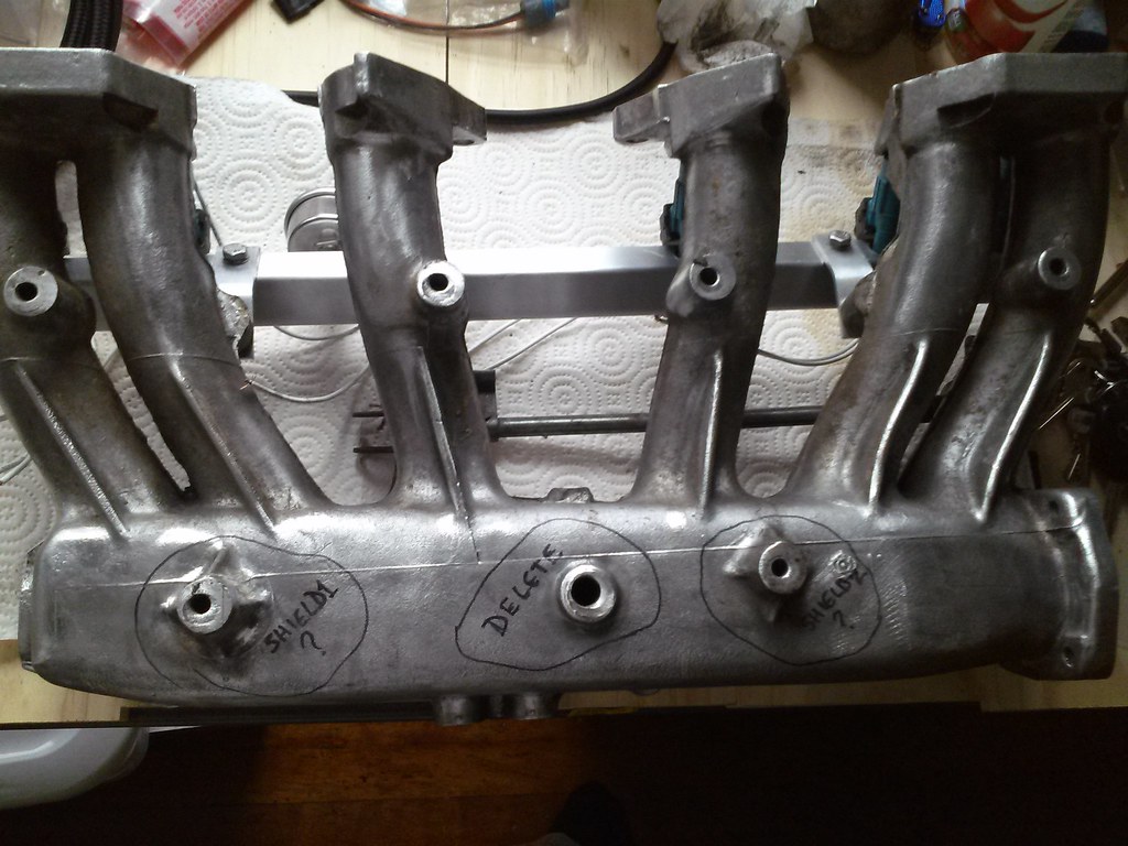
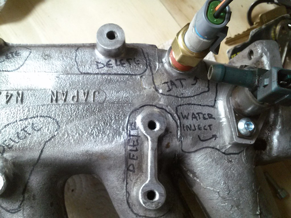
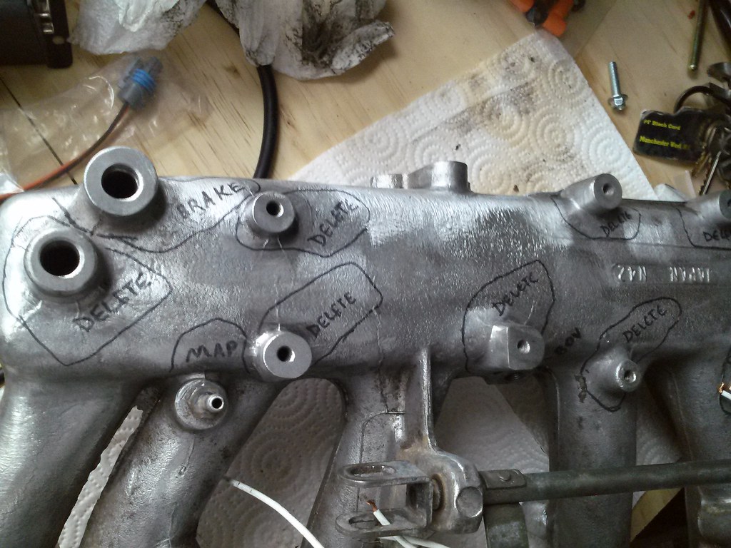
The old injectors have a complicated mounting system with a threaded manifold bung, a seat, several washers, and phillips-head screws that are IMPOSSIBLE to remove after 40 years of rusty neglect (I had to cut off 8 of the 12 machine screws, and managed to remove the studs for all but one - which still lives in the manifold). The upper and lower orings are both 14mm diameter, which absolutely requires a new fuel rail (Pallnet exceeded my expectations and got it out more quickly than I had expected - I should be able to pick it up at USPS tomorrow). I mocked up the injectors on an n42 manifold I had lying around:
While that looks fine at this angle, it really isn't. The lower 14mm orings don't slip into the manifold bungs, and therefore won't seal. They also won't spray against the rear-side of the valves, which is no good. I see no alternative but to take the intake manifold to a machinist friend and have her help it out by opening up the injector bungs. I'm going to try to mimic the seating angle/depth of the original injectors as much as possible, but the fact that I'm going from a single-hole fuel squirter to a 4-hole fuel sprayer might throw a wrench into the works. I don't really have any experience to draw upon, so I'm just going to dive in with both feet and try to put some data together.
In theory, the Pallnet fuel rail should apply pressure to the backs of the injectors and hold them in place. I see no reason to use the tapped holes in the manifold for extra pressure: most manufacturers have been using a rail to secure the injectors since the 90's.
That's all I have for right now, I'll meet up with my machinist/welder friend tomorrow and see what she has to say about the job (it sounds like a fairly straightforward milling job), and pick up the fuel rail to do some more accurate mockups of what I have to work with while I'm at it.
-
Good luck, have fun, keep all your fingers attached!
-
Well, the nor'easter 'bomb' skipped us, and we've had almost a whole week of above-freezing temps. That MUST mean you have an update ... right?
-
I'm currently implementing some EV1 injectors from a Ford Cobra (24# @ 42psi injectors, around 252cc/min - slightly LESS max flow than the stock injectors). However, the injector design should be quite a bit more efficient and be capable of making the same amount of power with slightly less fuel. I'm waiting on a new fuel rail so I've only been able to test-fit so far, but the mockups look promising.
-
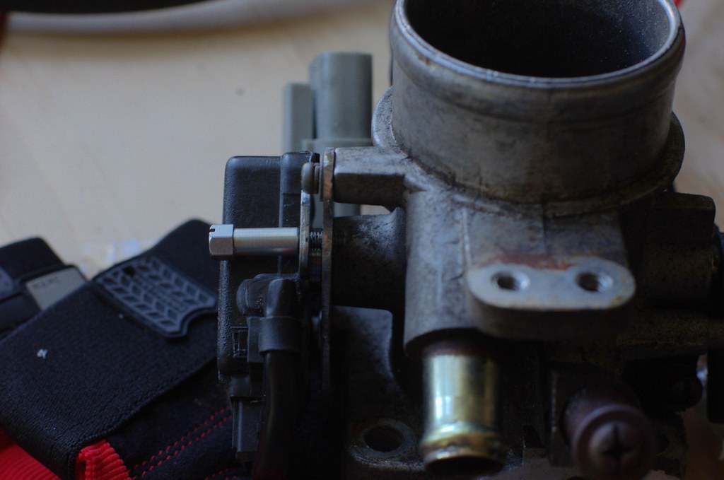
Still haven't had a chance to draw it up, but I realized the TPS has a bit of a lip around the input shaft opening. I hogged out the hole I had drilled originally, and it fit nice and flush! Also spent some time on wrapping up the wiring, every little bit of progress is a step in the right direction.
-
Rub it in why don't you
. I live in NH, and it was 15F at my house this morning....And we're getting a nor'easter 'bomb' tomorrow evening, if the weather is reasonably accurate.
-
+++
I'm pretty sure there are guys that do everything you've mentioned here with an MS1 on an L28ET but i might be overlooking something. You can surely do every bit of it with an MS2. MS3 is just vanity if that really is all you want to do and IMO kind of a waste. The benefit of sequential isn't a make or break thing with the power you want but it does change the ecu if you want to eventually go sequential.
You can absolutely do it with MSnS 1 or MS2. MS3 offers SD card logging, direct USB output (instead of serial -> USB adapters, which aren't a big inconvenience), 2 crank position sensors (VR+hall/optical/points), 16x16 data tables instead of 12x12, and 2stage nitrous control (could be used for meth/water injection instead of nitrous).
-
I'm still working on the 'minimum work for megasquirt on an l28et' article, but this is what I had ordered (mostly from DIYautotune - I highly recommend them, their support has been awesome).
Necessities*
1 x MegaSquirt Relay Board - Assembled Unit (MSRelay-C) = $94.00 @ diyautotune
1 x MegaSquirt-III EMS System - V3.57 - Assembled Unit w/ black case (MS3357-C_BL) = $559.00 @ diyautotune
1 x Wire Bundle (LG-WireBund) = $46.00 @ diyautotune
1 x GM Open Element IAT Sensor with Pigtail (IATwPiggy) = $22.25 @ diyautotune
1 x BECK/ARNLEY 158-0507 ka24de TPS = $55.43 @ ebay
1 x ka24de TPS mounting plate = $2.00 in supplies @ **
1 x 1k ohm .25w resistor = $1.49 @ radio shack
1 x Datsun/Nissan injector resistor pack = $0.00 @ included with the car, just under the clutch master cylinder)
12' x 16ga injector/ignition power wires = $5.49 @ autozone
Optional, but makes wiring a lot easier and cleaner:
1 x 460 Piece Weather Pack Kit (WPL_460-K) = $87.95 @ diyautotune1 x Ratcheting crimper for Weather Pack connectors, 14-20 gauge (T-3138CT) = $108.00 @ diyautotune
25ft x 1/4" braided wiring sleeve = $18.01 @ amazon
25ft x 1/2" braided wiring sleeve = $16.71 @ amazon
60' x PVC non-adhesive electrical tape = $1.38 @ amazon
36' x F4 Self-fusing Silicone Tape = $13.95 @ amazon
1 x LC1 wideband o2 sensor = $75.00 @ used from a friend
Total cost: $1106.66 (so far)
* Subject to interpretation, but this is what I'd consider necessary to minimize the amount of work you need to do.
** Technical drawing coming soon, along with a file to send off to your favorite 3d printer
Ideally, I would have liked to use mil-spec wiring connectors instead of weatherpack connectors, as they provide connections that are significantly more rugged (weatherpack is rated for 10 engagements, where mil-spec connectors are rated for 50). No matter what connectors you use, make sure they're secured and take the time to test your connections before installation. There's nothing worse than thinking you have a bad sensor, just to find that a wiring connection somewhere was bad. I'll put together a video describing my experience with Megasquirt on the l28et shortly, as there is a lot of misinformation and disorganized information out there right now.
-
I'd say the biggest consideration is whether you want sequential fuel/spark or not. MS3 3.57 is probably the best if you want bank-fire injection; If you want sequential fuel, you'll probably want MS3X 3.57 (3.0 is better if you ever want to break out the soldering iron). Expect to spend a month wiring, calibrating, and getting it running at minimum.
Also, if you don't have a wideband o2 sensor, the MS install is definitely the time to do it.
-
I haven't even peeked at mine yet; I just verified that a fuel pump was back there and ignored it ever since. I probably won't move forwarding with it 'till June or July, but you've got first pick on it if it's worth keeping.
-
I don't know what the inside of my tank looks like, but I'm strongly considering a well-baffled fuel cell this season. If mine is more solid and worth saving, you're welcome to it when I upgrade.
-
In regard to the video you linked, this is one of the things that is confusing to me about IAC control. This video seems to be using standard megasquirt and not extra code. In extra code the plunger closes off the airflow during homing. That is how it is explained in the extra forum by James. However, in this video, Evan explains that homing mode opens the airflow.
Do you know if Evan uses standard megasquirt or extra code?
I don't, sorry. I wasn't even aware that the extra code controls IAC differently than the standard code does. I've already contributed as much as I can to this, my inexperience with IAC and with extra would keep me from giving anything else worthwhile. I'm still working on getting my MS3 wiring wrapped up.
-
Thanks for the heads-up, I was wondering what was going on as well.
-
I can't offer first-hand experience, but isn't that just a basic stepper motor? I don't know how you've been testing it or what motors you've worked with specifically, but I imagine you'd want to start by measuring open and closed steps (sounds like you've done this, based on the arduino-controlled results), and measure the output MS is providing. Evan went through it in a pretty straightforward way.
I'm trying not to make any assumptions as to what you've done and what you haven't done, but I'd be interested to see your known-good measurements as to what actuates the IAC to open/closed as compared to equivalent MS outputs on whatever configurations you've tested.
-
If you want I'll print you up a spacer in ABS. No big deal. Just Email me the dimensions. ABS would easily handle any heat in that area. I'd even include the tech drawings and .stl since it looks really simple. If it makes it easy to use the more accurate KA24 tps it sounds like a great upgrade part.
I'll draw it up tonight. I could provide a Google Sketchup drawing or just an SVG if that makes it easier.
-
I've read that a lot of people swap to the ka24 throttle body on l28et's. I did some math, and came to the conclusion that a turbocharged 2.8liter only really needs a 50mm throttle body (up until around 300hp), and I can't think of a reason to swap to a ka24 throttle body in the near future. The problem with the 50mm l28et throttle body is that it doesn't really have a throttle position sensor. I measured the resistance output from the "l28et tps" and found it to be binary, either your throttle is ~75% open or more, or it's considered "closed". Megasquirt requires a real throttle position sensor (that offers different resistance at each throttle angle), I decided to swap to the ka24de tps.
I immediately noticed that the ka24de tps fits the throttle shaft of the l28et throttle body, but somewhere along the lines the mounting hole locations were changed.
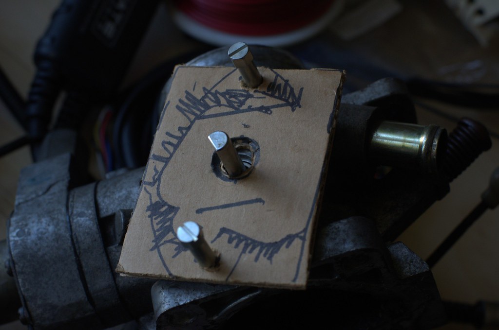
Not a huge deal, I thought. I'll just make up a little bracket to mount the ka24de tps. I grabbed some cardboard and a sharpie and started to mock up a design.
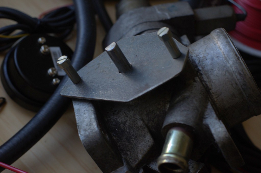
I looked through the metal stock in my 'garage' (it's a sad, sorry excuse for a garage, but it generally works for me) and found some 1/4" steel plate that would work well enough for this little bracket. In general, you want to try to avoid putting steel against aluminum, as the materials react to all environmental conditions differently and can actually speed corrosion, but this is a small and non-precision part so it's not a big deal. I took my template and scribed the steel stock, and drilled a couple holes:
Everything looked good at this point, so I decided to clean up the shape a little so it wasn't an awkward triangle on the throttle body.
Unfortunately, I found a problem at this point. It's not a dealbreaker, and is easy enough to solve, but I'm pretty sure it's going to cause me to make a new copy of this part.
The l28et throttle shaft bottoms out on the ka24 TPS, where the l28et "TPS" was a little deeper and fit flush. I'm going to take some measurements of this prototype, specify that the thickness should be doubled (1/2" thickness), and either send it off for 3d printing (a nylon printed part would be perfectly fine for this) or have it milled out of aluminum.
For the time being, I'm just going to keep everything as-is and stick some washers in to space it out, but I'm not happy with that as a long-term solution. I'll make the final technical drawing (and/or 3d file) available for download, and might order a small stock of these to sell if anyone else is interested.
-
That emblem looks incredible! Would it be worthwhile to do a small production run of them? I know I'm interested in getting my hands on one.
-
Oh man! You're right where I was this time last year. Keep with it! And yeah, the aluminum foil wire is the shielded one.
Be careful stripping the outer shell. The inner wires are little and can easily be nicked.
I'm about to fire mine.....If the temperatures would rise just a little...
You're really close!
I'd say forget temperatures altogether, but you probably don't have a fidle circuit either, huh? I really can't wait to get this thing running, then I can start the REAL work and prep for Ascutney. If you have yours running well, you're only a handful of hours away from our hillclimb events. It'd be really nice to see a second Datsun (or even a second Nissan) climbing the Vermont mountains with me. Lots of Subarus and lots of VWs, but not much Jap Tin out there. More info: http://www.hillclimb.org/
What it's like:
-
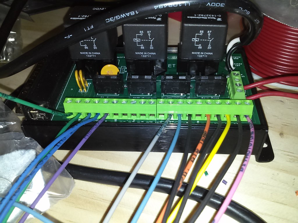
The only things left to wire in are the 1k-ohm .25w resister for the distributor->megasquirt signal and to figure out what this crazy 3-wires-in-a-silver-sleeve actually do. It would've been really nice if diyautotune included some documentation with their wiring bundle on intended uses for the wires. I'm pretty sure the crazy silver wire is the shielded one (haven't looked carefully at any of the ends) and should be used as the cas (tach) -> megasquirt signal cable.
There are a TON of spare wires from this kit. They really just aren't needed, unless you're using some of the 'special' circuits for things like fans or nitrous.
-
I can say 100% that an l28et is a hall type. I would assume, based on that, that Nissan reused the same distributor sensor in the non-turbo as well.
[EDIT] Incorrect(?), my research may have lied to me. Refer to NewZed's post.
-
What safety equipment is required for a street car to participate?
I'm pretty interested, too. I would want a 5speed for that drive, but the Tail would have to be a great time. Is there a breakout time, or is a cage required for everyone who runs?


 . I live in NH, and it was 15F at my house this morning....
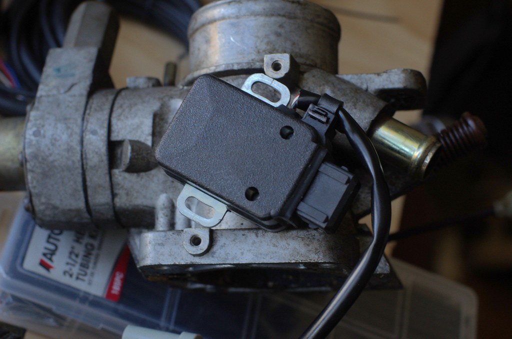


EV1 Cobra Injectors
in Fuel Delivery
Posted
Pallnet's mounting brackets seem to do a great job, I just need to stop trying to stuff a 14mm component into an 11mm hole.
Right now, I'm actually going to a SMALLER turbo. I got a great price on a .48 t3 that's in great condition, and I'll sacrifice a little size in order to have a more reliable, trustworthy machine. Eventually, I may go to an upsized compressor, but that's a season or two away - I'd much rather get the most out of a low-powered engine and solve the PROBLEMS with the car rather than trying to improve things that don't yet need improvement.
I'm just going to run a catch can in place of the PCV system. I can't think of a downside to that, and catch cans are pretty dead simple to build (or ebay).