

Jesse OBrien
-
Posts
664 -
Joined
-
Last visited
-
Days Won
1
Content Type
Profiles
Forums
Blogs
Events
Gallery
Downloads
Store
Posts posted by Jesse OBrien
-
-
DIYAutoTune was great to deal with, but the USPS was decidedly not (as I've come to expect from them). I just ordered the ratcheting crimping tool from them, and they were nice enough to ship it via FedEx or UPS (I don't know/care which) so I'm pretty confident that I won't have to wait 2 weeks for it. In the meantime, I'm finding the megasquirt documentation to be awful when it comes to specific basics.
I can't figure out why, but the 3 leads to the relay board (12v+, ground, +signal) are just solder terminals. I had a friend with a lot of soldering experience weld on a few leads and connect a weatherstripping end to it. This seems like something that should be done from the factory, as most of the benefit of buying the relay board is that you don't have to solder it together yourself.

I also ordered a couple of sensors to go along with it (an iat sensor and a throttle position sensor from a ka24)
I'm still trying to find some documentation on which leads are ACTUALLY required, why there are two signal wires per bank of injectors (along with the +12v constants). I haven't been able to find out what type of signal the l28et distributor provides, or how to wire it in, and getting documentation on what each of the relay board connectors actually go to has been a frustrating experience. The megamanual is a long, rambling document that goes from hopelessly vague concept to razor-fine specific details within a single sentence, and I'm left without many specific about the l28et or its sensors. Trying to search through forums (either megasquirt forums or hybridz) is also quite frustrating, as the results fail to answer the (very basic) questions I still have. I'm still going to have to do more research and information-gathering, but it isn't encouraging that nobody seems to have put detailed information together since a hand-built MS1v3 writeup was written. I'll get through it, gollum has been particularly helpful in answering questions (despite the fact that he's never installed megasquirt, he seems to be the most knowledgeable about how it should work with Datsun engines - That either says a lot about his research abilities or about other peoples' interest in sharing their experience).
Finally, in other news, I met up with John from Bad Dog today and picked up a few parts to start prepping this car for the race season. I grabbed a used fiberglass FIA-approved seat:
And a 5point cam-lock harness to accompany it:
And a box of (again, used) suspension goodies and door parts I've needed for awhile:
All told, it's been a very good day. As long as I can finish up the relay harness wiring this week, I hope to try starting the car next weekend.
-
I guess this isn't so far from what you're talking about. This is what my 280z looked like when I purchased it.
-
Good catch, but both are readily available online ... but the actual latching mechanism isn't, and mine doesn't spring like it used to. As far as I can tell, these aren't serviceable, just replaceable.
-
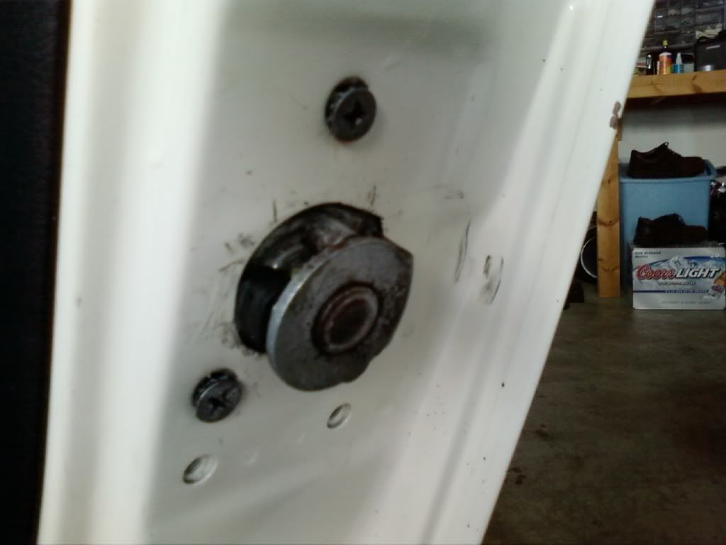
I need a working driver's side latch-piece (not sure what they're called):
-
1 x MegaSquirt Relay Board - Assembled Unit (MSRelay-C) = $94.00
[MISTAKE - I've asked to cancel this portion] 1 x MegaSquirt Relay Cable (MSRelayCable) = $85.00
1 x 8' MegaSquirt Wiring Harness (MS1 / MS2 / MS3 Ready) (MSHarness8) = $67.00
1 x MegaSquirt-III EMS System - V3.57 - Assembled Unit w/ black case (MS3357-C_BL) = $559.00
1 x 460 Piece Weather Pack Kit (WPL_460-K) = $87.95
1 x GM Open Element IAT Sensor with Pigtail (IATwPiggy) = $22.25... plus cheap shipping
I think MS2 is $114 cheaper ($445.00 current price), and the weatherpack and IAT sensor add another $100, then there's another $85 for the cable I mistakenly ordered (it's redundant, it seems) ... so your numbers certainly add up.
-
$950 later, my MS3 equipment is ordered.
-
Thank you for taking the time.You could put MS3 on the L28ET without changing any sensors. The big "but" here is the sensors have room for improvement to make the engine run more power with better economy. Let's start with the sensors:
MAF- Sure you could keep the stock one and get it to work with MS3. I prefer a MAF, I run a Z32 300zx MAF and I love the drivability. Or you can do MAP, just use the onboard unit on the 3.0 board until you know more about megasquirt to want a different one.
The plan is to use the onboard MAP and keep boost levels low. I'm not adding an intercooler or any kind of water/meth injection this season, just trying to make the most of the stock equipment. I just ordered the 3.57 board, as I intend to modify the board as little as humanly possible (read: no modifications) to get this engine running reliably.
Head temp sensor - I use it and it works great. I can post up what I use for calibration if you want.
That would be superb, or if it's already been posted I'd be perfectly happy with a link to that thread (whatever forum it may be on).
TPS - this is really something that needs to be replaced for a MAP based system. Accel enrichment won't work on the stock switch, but a unit out of a newer 240sx can be used. A MAF system doesn't necessarily need a cell enrichment.
The stock l28et 'tps' is kind of a joke, so this makes perfect sense. I've seen the ka24e tps installed, and it seems really straightforward to me. Looks like a robust configuration.
Know sensor - off the shelf, the MS can't read it. The knock module for MS uses a different type of unit, so the stock unit will be unused.
I'll have to do some research on this to figure out exactly what I need to order.
Distributer - it is fine for the stock coil and igniter. You will just have to modify the 3.0 board with the appropriate pull-up resistor. If you want to go more wild, then an aftermarket trigger wheel will be needed for coil-on-plug or external coil packs. Its available through DIY Autotune.
I remember reading about this in the MS1/MS2 installation guide on diyautotune's tutorials/articles section.
Injectors - The stock injectors are low impedance so a resister will have to be wired in. If you are staying with batch fire, which is all you can do with the unmodified distributor, the the 3.0 board can handle the injectors without a resistor. If you use an MS3X to run the injectors, a resistor pack will be needed. I use a Nissan version, available through various 6cyl Nissans. I have also used Honda units as well, and they have a pretty spiffy heatsink on them.
Right now, I'm just planning MS3 in batch with the stock distributor. I'd love to swap out to a better fuel delivery setup (with a real fuel rail, a reliable fuel pressure regulator, etc) ... but I'm going to put that off as long as possible.
Air Intake Temp - This is needed if you plan on a MAP based system. I mounted mine in the aux injector hole, just drilled and tapped. I used a Chrysler 420a sensor from a Neon or Eclipse. I can also post that calibration too.
I picked up what seems like a simple solution: the GM closed element IAT directly from diyautotune.
Idle control - I don't have any, but some use Bosch units with success.
I haven't done any reading on this yet, but I'm going to be at all different temperatures and altitudes so idle control is probably worth having.
-
I searched. The signal to noise ratio was really bad.
I'm gearing up to install megasquirt 3 in my l28et, but I've had a hard time finding definitive documentation on what works and what doesn't. I've come across lots of anecdotal information, but I'm wondering if someone has put all the facts together into one place for ms3 and the l28et. Which sensors are typically used? Which distributor/coil options have given the best results? At this point, I'm just trying to get the car to run with as little hassle as possible, and installing MS seems like the fastest, most straightforward way to do that.
My most important question is:
What components MUST be replaced or worked around when installing ms3 in an l28et?
-
Jan 29th will be my 5-year anniversary here! I still have several hours before new year's here.
-
It's been too cold to work on this outdoors, so I'm ordering all the supplies for an MS1 kit this weekend and having a friend organize it into a plug-in-ready kit for me (in exchange for some cash, of course). That way I don't have to deal with any pre-existing problems, and I have known-good brand-new EFI for somewhere under $1k, after all is said and done. He'll assemble the components, load the firmware and a base tune, test it on his 83 l28et, and ship it all out to me so I can get it around the block.
From there, I can FINALLY start tuning and stop wondering which wire is which (the MS harnesses are labeled intelligently, none of this color-coding nonsense). With a fair amount of luck, I'll be able to drive it to the house I'm planning to start renting on Feb 1. I'll keep the updates rolling in once there's something worth mentioning.
-
One of your pics shows 2 fusible links
I definitely only have one fusible link connector (it has two fusible links in it).
The five wires 2 green, blue/red, white, yellow is definitely for the fuel pump relay. You can live with out that and wire pump to ign on, till you get everything setup
Do you have the relay for the ignition wires
There's only one relay in the engine bay, and it sounds like that's the fuel pump relay now. Unless the ignition relay is bundled up under the driver's side dash behind the firewall, I haven't seen anything that resembles ignition wires. I have a coil (unknown model, don't know if it's from the l28et or l28e and don't know how to distinguish between the two) that appears to be connected to the end of the headlight wiring bundle. It has good + and - on its two posts, but I have no output from it. I think I've identified the underdash ignition connector (on the ECU bundle) but I'm still putting together all the pieces from BumbleZee's howto with that. Those are my facts, at this point.
I have successfully performed two L28ET into S30 swaps. Both were into 280Z but my experience in both cases revealed faulty ECCS connectors. Horrible running, popping, poor idle, rev-limiting, lean running, all of the above are symptoms of bad connection at the two ECCS plugs.
When you get to that point, push and pull each wire, directly at the back of the connectors, with the car running, and you will instantly identify the problem areas. Adding dielectric grease, and carefuly "preloading" the pins in the ECCS connector by slightly bending them to one side, seems to alleviate the issues.
Not sure if it helps, but I have a pretty simple wiring schematic for the swaps over in the downloads section of hybridz.
http://forums.hybridz.org/files/download/4-turbo-swap-wiring-diagram/
That doesn't surprise me at all, the l28e connectors were simply falling apart on me. The ECCS connector is pretty solid, I've been poking the pins like mad with a test light, but they don't flicker or wiggle. At this point, horrible running would make my day.
Winter plans involve a pile of reliability improvements, including a new from-scratch wiring harness and Megasquirt, fuses that aren't made of glass, and properly weatherproofed connectors. Today, it just needs to go, with both spark AND fuel!
On some of mine, out of movement of harnesses and wanting to clean things up, or shorten/extend this or that...I replaced stuff with Weatherpack GM-Style connectors...
Some of those ECCS Plugs were literally filled with green corrosion byproduct, and it was "I don't have the time for this crap!" Snip, Crimp, and Stab and I was on my way.
I think this ties in to my lack of problems after swaps like Cygnus mentions. Whatever is valid in chassis originally is compounded when you swap and disturb maybe tenuous connectors at best then hope they reconnect later.
These connectors aren't as bad as most, based upon my experience. I'm sure they aren't perfect (I'm not crazy about these connectors even if they were brand new), but through all the test-light pokes and prods I've been doing, I haven't had any flickering signals or wiggling pins. I believe the hardware should be good to go, if I can sort these wires out and get the critical components connected to each other.
-
Hahahaha so your configuration is about as nonstandard as possible. Got it. Still, identifying parts is massively helpful to me. I'm really pressed for time, so you couldn't be providing this reference information at a better time.
-
My car is a true hybrid. I believe both relays are on the passenger side near the fusible links. I believe the 5 wire would be the fuel pump relay. That is run from the 2nd pic i sent you. The 2nd pic is from the ecu. the 3rd is the other side of that connector. There was a blue with red stripe wire that is the signal I believe, if you follow the diagram pic I sent you you should figure it out. Going to be tough with you color blindness issue.
The 2nd/3rd pic shows the black/white stripe that needs ignition on.
Blue/red stripe goes to relay
I only have one set of fusible links, and only one relay on that passenger's side. I'm not saying there shouldn't be one, but is it possible there is a difference between the year I have, and the year you have? What year l28et is your engine?
It looks like the PO removed that connector altogether on mine, or it never existed on my year. I just took a look, and it's just not there (along the driver's side frame rail, in the engine bay). I'm guessing this mess used to be that connector:
-
You should have 2 of these. One for igniton and one for fuel pump relay.
Only one, where would the other be located (physically)?
I have two versions of that diagram printed out, but it's specifically for an 83 l28et and doesn't indicate the physical location of any of the components.
-
Hugely helpful, but do you know which connector that actually is? Looks like 4 wires, where mine seems to have a spare wire stuffed into it.
-
New facts:
I've verified that my ECU is getting power. One of several green wires in the engine bay (the thickest green wire, ~14ga) powers the ecu and injectors, it turns out. Some wiring diagrams say that should be red, brown, or white/red ... but it's been inconsistent. On my car, it's green.
I'm having a tough time finding specific differences between the 81-82 wiring and 83 wiring, but the 83 appears to be the most problematic so that's all I could find documentation for. I still have no idea which engine year I have. The best documentation is still the http://forums.hybridz.org/index.php/topic/34469-a-quick-fi-and-ignition-280zxt-to-s30-turbo-swap-guide/ series from bumble zee, but it still has a lot of holes. For example:
- What does the ignition harness look like?
- Are there more relays on the 83 than on the 81-82?
- Exactly which sensors are required to have the car run?
- Where is the FI relay physically located?
- What does the FI relay look like, and how is it actually wired?
- Where is the fuel pump relay physically located?
- How can I identify which ignition system I have?
After realizing that I really don't have enough facts to go on, I started labeling all the disconnected connectors I have to establish a single source of truth. I don't have a lot of time remaining, so I'm looking for specific facts. Because of that, I'm organizing the information that I already have, so hopefully some of you who have actually seen an in tact system can help me to identify the unknowns that I'm dealing with. Bear in mind that the previous owner had a friend's cousin's dog's brother's owner do some of the wiring for him, and I received no documentation on what was done or wasn't done. Please feel free to add notes or purpose information into the following spreadsheet.
Canonical Wiring Identifcation Sheet
At this point, I have no spark (the coil's + source has +12v, but no power is coming out of the output plug to the distributor). I don't have a good way to test the injectors, but I did verify that the ECU has +12v for all 6 leads to the plugs (the bottom row on the three-row connector). Now that I finally have power to the body, I can start diagnosing more important things like ECU input/output, ignition wiring, and fuel pump wiring. With your help, I could just power through the cold tonight and have it running in the morning.
Just in case any of you can't see the document I linked to, I've attached a PDF working copy here: 75 280z and l28et Wiring Reference - Sheet1.pdf. Once I have all the connectors documented, I'll republish it with all the latest info.
-
Why not just bolt one of the carbed intakes on and crank it with a screwdriver and some gas in the carbs to get it primed? U can run a fused hot wire to the fuel pump on a switch and manually regulate it...
Retuning them to run on a turbo block along with getting the n/a ignition to run on a turbo block would take more than today. It would also require rewiring the entire car, because the problem I have (as I've said several times) is that there's no positive anywhere.
I entered and bolded the wire colors as they appear to me. I hope this helps.
You sir, are a god among men. I can't express how much it helps.
I bought myself the weekend to finish working on it, so I cut back all the looming starting at the starter to see where power goes from there. After another hour of cutting through crunchy wires, I found an unidentified connector that went to nothing.
I have yet to see any reference to this in any of the wiring diagrams I've seen, and it's the 'weak link' that's keeping the block of 'fusible links' from running. Because the documentation doesn't explain this and I haven't had any responses explaining how the car received its +, I applied a logical temporary solution:
Suddenly, several of the car's systems started working. Now I get to put Namor's input to good use, and figure out how this mystery relay is intended to work, as well as where all these other miscellaneous wires go:
The wiring diagrams are absolutely worthless to me, as it doesn't indicate any physical locations of the wires. I'm going to ASSUME this relay is the EFI relay and wire it as such (receives signal from the ignition tumbler). I'm not sure where the 12v constant source is intended to be, but I'm strongly inclined to wire a fuse in before the relay. Does anyone know what kind of amperage the stock ECU requires?
-
Well, good luck then. The feeling of knowing the function of the wires and that they're connected correctly is much more satisfying, to me, than the thrill of connecting the battery or turning the key with no firm knowledge that things won't go up in smoke. But I'm kind of boring.
If I don't have it running in two evenings (around 6 hours of work in the cold with a flashlight in my mouth), it gets impounded and I never see it again. At the moment, I really just want it to limp, so I can work out the details later when I'm not directly under the gun. I appreciate the recommendation of striving to do things right and invest time to understand systems, but I don't really have the luxury of time at the moment.
-
Figure N
Ok, this is in the same loom as the FI relay. There are 3 wires that you will need to cut and splice. First off, don't cut any wires that are going to the plug for the FI relay, those need to stay intact. There are 5 other wires not attached to the relay. They are from left to right;
-Green - Constant power (Needs to be run to a 12+ volt constant)
-Black with white strip - Switched power (Needs to be run to a 12+ volt switched power)
-Blue with red stripe - is switched power for your fuel pump relay (has 12+ volts when key is on, will have power for 5 seconds if car is not running to prime the fuel system, and will have a constant 12+ volts when car is running.)
The yellow and white wires you see bent off to the side you will not need and wont be using
Figure O
This plug is for fusible links. Those white wires on the left you will not be using,
but the brown and green wires go to the + post on the starter.
And that is it for your FI harness.
I hate being colorblind. Are these the wires I'm looking for? The names of the colors sound the same.
You should change the focus of what you're trying to do. Don't worry about wire colors or what this plug connects to or any of that. Sit down with the wiring diagram, the big connector to the ECU, some tape or stick-on labels and a pen, and an ohm-meter or continuity tester. Test each pin in the ECU plug for continuity to every wire end. Some of them will be pretty easy, like the pin for the CHTS should be connected to an EV1 style connector. Others might require a lot of probing. Or do it backwards and pick a wire end and just stab your probe in to every ECU plug pin until you get a hit. When you figure one out, label it with the pin number and/or (preferably and) its purpose to the ECU (example: injector ground, CHTS connection, etc). When you're done you can decide how to connect each component or power source to the proper pin at the ECU. Fuses, relays, etc. will be easier to figure out once you know each wire's function.
My multimeter died, apparently it's too cold for it. The LEDs don't give meaningful output any more. It's starting to get chilly now (21F currently on my thermostat) so sitting down and spending a lot of time stabbing in the dark driveway.
My test light is the best diagnostic equipment I have available for tonight, but I'll try to make time to replace my multimeter tomorrow if that's what it takes. No wires on the ECU connector or the ignition terminal have continuity with the battery. Once I have some continuity, troubleshooting becomes much easier (it might actually even run at that point).
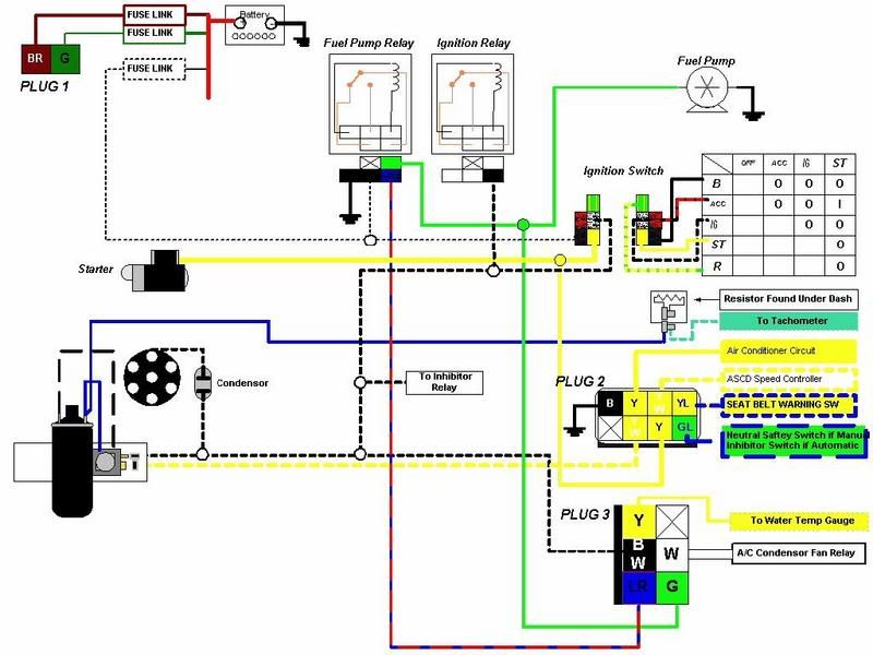
Finding facts on how this was supposed to be is still proving difficult. This image:
indicates that I should have two fusible links on the passenger's side, but I only have one. I assume that's an indication that I have a year of l28et that this person doesn't have, but I don't know if that means I have an 81, 82, or 83
seems like a fairly straighfroward diagram, but it's incomplete. I need to know what color the fuse link that powers everything in order to trace it to the fuel pump relay or ignition relay (I still need to identify which relay is which, as well).
I also took a look at the starter motor, where I realized there's a ring terminal on the + lead that burrows away into the wiring harness. I've been trying to cut back the cold, crunchy electrical tape to see where that wire goes, but it's very slow going, even with snips.
-
Maybe I'm getting closer to figuring this out. My girlfriend was good enough to try identifying which wires were which colors, and I organized them a little better into a micro-diagram:
I'm relatively sure that this "brown" color the wiring diagram speaks of gets constant 12v directly from the battery. I'm still poring over it to figure out which components I really have, though.
I also discovered that the ring terminal that's attached to the + lead of the starter apparently provides power to much of the car. Anyone know what color that wire is, or where I might find it on the wiring diagram?
-
I have a confession to make.
I'm colorblind
I know, it's hard to just come out and say it, but we all have things we need to admit to. Now that I've got that off my chest, I need to ask the really stupid questions. Partly because my previous owner didn't pass on any wiring documentation on his progress, partly because I don't know what year this engine's from, partly because the WEALTH of information about the l28et takes days to paw through, and partly because I'm colorblind ... but also because my landlord pulled the rug out from under me and surprise! I no longer have a garage bay to work on this car. That means it needs to be inspected by this weekend, or it gets towed. To get it inspected, it pretty much just needs to be able to sputter around on its own power in only two (20-degree) evenings. I really need your help.
Let me start with a lay of the wiring land. Here's what I know for sure:
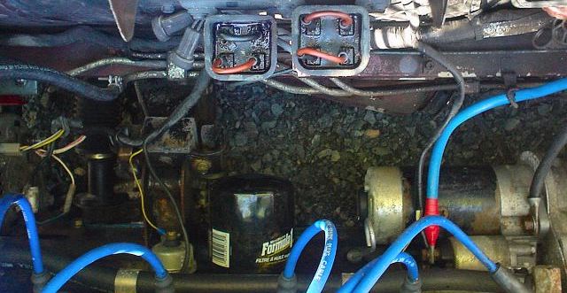
- This engine only appears to have one fusible link box (pictured at right, 2 inputs, 2 outputs, 2 wires connecting the two). One of those circuits has continuity (closer to the camera), the other does not.
- My ignition tumbler has no power coming in to it, and therefore does nothing at all.
- As far as I can tell, the ECU also has no power.
- When I received it, there were 3 wires connected to the battery + terminal, connected via a yellow crimp connector:
- white (it's a trap!)
- green
- red
(blurry, but you get the picture - ha! pun!)
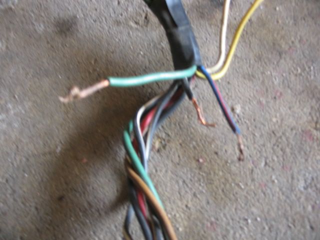
- Because nothing appears to work, I thought I'd start there, hoping to uncover some obvious fix. Unfortunately, now I'm just more confused than ever. The red and green wires appeared to run to a relay just off-camera, so I pulled back the looming, and uncovered these disconnected leads:
The more observant among you may notice that there are more than three now.- red - already discussed, connected to +
- green - already discussed, connected to +
- color? was disconnected
- color? also disconnected
- is actually an IMPOSTOR (it was never white after all! it was [insert color here])
- and the 6th is new, but was also disconnected
- Here's the wiring mess that's looming (ha! pun again!) before me ... it's what's coming out of the loom.
(left-to-right)- yellow(?)
- color?/color?
- color?
- black(?)/white
- color(?)
- white
- green(?)
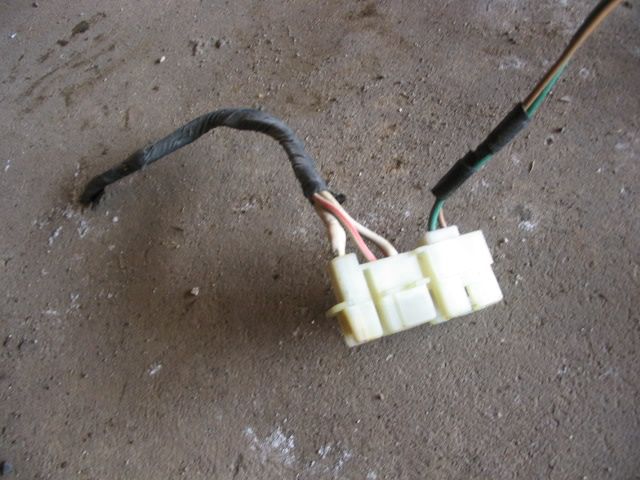
- Finally, here's the backside of the relay in question.
- Coming out of the loom, but not connected to anything at all:
(top to bottom)- color?
- color?
- color?
- color?
- white
I'm sorry for the piecemeal photos, I'm working on a proper wiring diagram, but needed a good way to identify all these wires. I'll work on a numbered wiring diagram with a bunch of question marks shortly.
I know the fuel pump is a concern, and the igniter is a concern based on the research I've done. How concerned should I be about them? Am I risking lighting fires or frying the ecu (assuming it's a working unit to begin with) by getting everything else hooked up first? I have 0 problems with wiring virtually everything into toggle switches and running a screwdriver across the starter posts to start it up ... as long as it starts up. Once it's running, I can probably work my way through any body wiring that the car might need, but I really need to solve this part of things RIGHT NOW.
Thanks, guys. Please come through for me.
- This engine only appears to have one fusible link box (pictured at right, 2 inputs, 2 outputs, 2 wires connecting the two). One of those circuits has continuity (closer to the camera), the other does not.
-
Hehe, Yay! I can steal Jesse's car now... okay, no way I'm headed to NH anytime soon, much less do it to steal a car. Might be a good idea to stamp or inscribe that code in the glovebox door. or write it in your service manual, if you have it still. (I do
). It would be interesting to know what range the codes Datsun used back in the day, Do you think it was the full 10K codes, or just a specific subset. I'm sure they'd eliminated the 3333,4444,5555 etc combinations.Having the key won't help you steal it, you'd have to get it running first
You'd also have to fend off my crazy drugged-up neighbors, then contend with the crazed owner with too many guns.Based upon what I've read, they used a VERY limited subset.
-
Sometimes, if you're lucky, the code can be found on a small piece of white paper stuck to the inside of the glovebox lid. Most time though they're illegible due to the years.
That was the first place I tried looking, but had no luck on this car. If that piece of paper was still there, the text was long gone.
-
Bandwidth is the big problem with using a tablet. Megasquirt really is the right way to do this, with an Android interface that connects to it and offers your outputs. You could write a small Java application to manage the primary power relay that feeds megasquirt, and let megasquirt handle everything from there on out. Generally speaking, the ECU and Carputer are separate entities, for several reasons. ECU's are considered embedded devices, which are generally much more stable and reliable than machines that run several layers (operating system, driver layer, library layer, application layer). The Carputer should interface with the ECU, but should not run the ECU code.
You could reasonably easily make a 'body control unit' out of an Arduino, which wouldn't be a bad idea at all. It can process several inputs/outputs and control relays (with an output boost in voltage). I definitely wouldn't trust Android hardware (or operating systems) to directly an engine, though. As a tuning tool to write to an ECU, it's a great choice. As an ECU, there are far too many possible points of failure for me to have any faith whatsoever in that solution.
These are just my thoughts after 10 years of high-availability software development and systems administration. I'm no electrical engineer or ecu specialist, so someone else may be able to speak to that better than I can.


 ). It would be interesting to know what range the codes Datsun used back in the day, Do you think it was the full 10K codes, or just a specific subset. I'm sure they'd eliminated the 3333,4444,5555 etc combinations.
The Slave Z build thread.
in S30 Series - 240z, 260z, 280z
Posted
I'm definitely inspired to finish my build. Any time I see a zcar, it's good for around 30 units of inspiration.