SH4DY
Members-
Posts
136 -
Joined
-
Last visited
-
Days Won
5
Content Type
Profiles
Forums
Blogs
Events
Gallery
Downloads
Store
Everything posted by SH4DY
-
Alright, so I think the game plan is: Straighten out the cap and get the alignment and fitment sorted. Use the frame and cap as a clam shell for a plug form(apply a bunch of packing tap, and then mold release on opposing sides). Pop the plug out, smooth over, epoxy/glass, add mounting provisions and then finish coat (paint, carbon, maybe a little of both? Sounds simple, right?
-
'77 280z aka Project Tetanus (LS6 383, T56)
SH4DY replied to SH4DY's topic in S30 Series - 240z, 260z, 280z
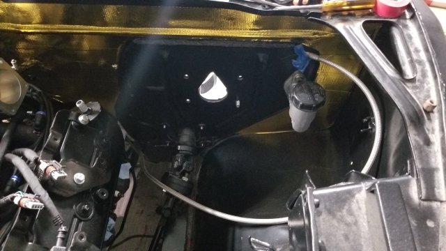
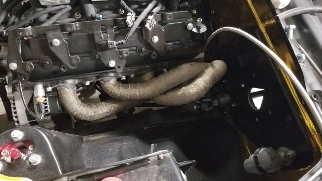
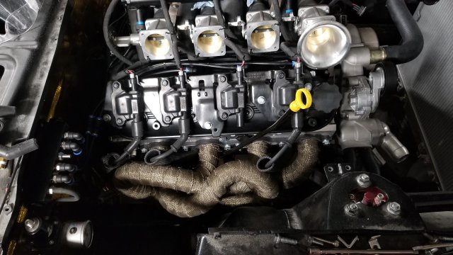
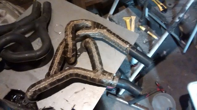
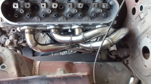
Fast forward and Clutch master is mounted, headers and ITB's are on, fuel lines are ordered and hoping for a first fire in the next coupld of weeks -
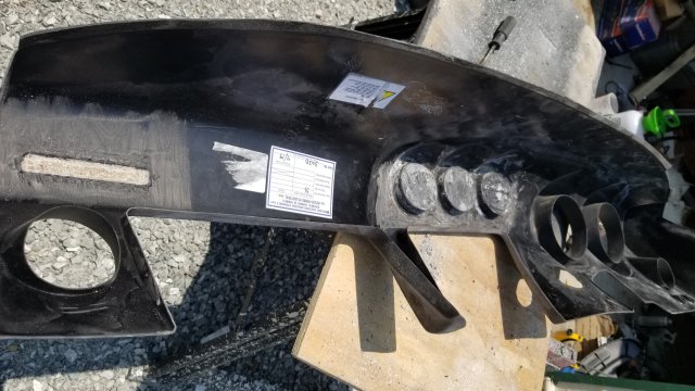
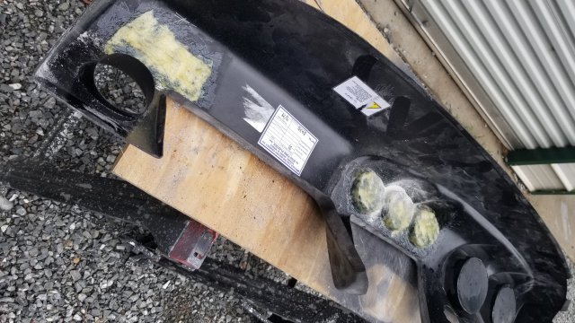
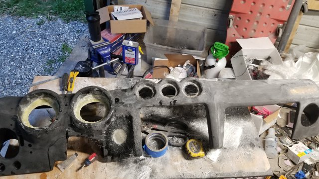
Well, I started down the path. We'll call it progress. Initial rough up and flame treat. The backing pieces were secured with plastic weld epoxy initially and then gone over with alternating layers of the g/flex 655 and West 105/207 and glass with sanding in between. If I had to do it over I would have just made some 90 degree brackets with thin metal and epoxied those on added rigidity. And what it looked like before the finish cuts for the gauges. Between all the layers, the back plates are probably between 1/8" -1/4" thick. Plenty sturdy enough for the gauges. Now I'm at kind of an impasse about how to secure it to the frame. Originally I had planned on using the factory mounting holes and putting tapped spacers in between the cap and the dash and then securing with a bolt. But, between the cover not fitting perfectly to begin with, and then slightly warping with the flame treat it's off enough that the glove box won't line up. I'm not concerned about the center panel since I was just going to make a flat plate there either way but the whole thing is pretty flimsy. I can heat again and probably get it close but it will involve adding a lot of support to get rid of the flex if I don't address the void. So, now I'm toying with filling the void between the cap and frame with expanding foam to help with the rigidity. But with that comes issues about making sure the alignment is dead nuts before the pour, making sure the materials are compatible and will bond, etc etc. Pain in the ass is what this is...
-
At $800 +shipping across the country, that's still a little rich for my blood. I'm still going to try and doctor the current Accu Form skin, it's just going to take a little more work than I'd thought. I did discover there is a local West Marine so I was able to pick up some g/flex and some 105/207 resin/ hardener for the skin. I went over everything with 80 grit and flame treated before applying the g/flex. Side note: I went with the 655 vs the 650 because it specifically mentioned hard to bond plastics. It is definitely more of a gel than most of the epoxies I've used. It says it can be used to fill voids I think up to .5" without needing to be reinforced. I tried laying in some glass strand just for more grip for the upper layers and it really doesn't wet out very well. BUT (!) when it dries - this stuff isn't going anywhere. That's as far as I got yesterday. I've still got to re-sand it and lay some more glass on the back side to reinforced around the gauges, then I can move on to the top and figure out the mounting. I'll get some pictures up of the process.
-
There are several youtube videos and threads showing his work and it does not seem to be up to snuff (or it wasn't - he may have changed his lay up and resin methods). There was also a considerable lag in shipping (3-4 months vs the 4-6 weeks shown on the site). Again, all of that may have changed but I'm still a little leery when we're talking about dropping $1k+. But it still may be an option because: I tried reinforcing and adding backing to the gauge cut outs on the Accu Form cover and failed miserably. The website said it's made out of ABS but I doubt it considering how it reacted to ABS cement (probably the strongest chemical weld available when dealing with ABS). The cement didn't really take to it, even after scuffing with 80 grit and cleaning with the ABS cleaning solvent. Not only that, but it actually melted off the top layer of the dash where I had applied it. And the fiberglass didn't do a great job wetting through either. So epic fail all around. My next attempt will be with a two part epoxy. And if that doesn't work, then I'll resort to using this cover as a mold and just making a new skin.
-
So I've got the OBX (Jenvey knock off) ITB's for my LS6 based motor and I'm trying to sort out a better way to tie the throttle bodies together. I can take pictures later but right now, the throttle shafts are tied together by a little arm on the first TB that presses up on a set screw on the next throttle body to open the blade. Then the second presses on the 3rd and so on. Then, there is a (flimsy) piece that sits on the top side so when the first TB closes it'll coax the second one to close as well if the spring tension isn't enough. I get that the set crew is there to balance the throttle bodies BUT I have drilled and tapped every runner (about 2" off the head as that was the only place with enough meat to tap) and have 5/16" vacuum line tying them all together at a distribution block. I did this for a couple of reasons: one, I didn't want to run only Alpha-N so I needed a MAP reference and two, I thought it would help balance the runners. (And maybe my logic is jacked here but if you have a high vacuum and introduce a lower vacuum ( a leak essentially) then the higher vacuum can only pull as much as the lower). And if this holds true, then I wouldn't need to sync each throttle independently and I could have a rigid linkage between the throttles for a crisper response instead of the daisy chain approach. Thoughts?
-
Lq4 hci +175shot 260z Goes racing
SH4DY replied to DcrDavid's topic in Gen III & IV Chevy V8Z Tech Board
Is that 2,600# with driver? I had always thought these were around 2,300-2,400# wet. Also, I'm really digging the wheel/ tire combo. Mind sharing the specs on those? -
So I think I've got one of the weird long nose R200's with a rectangular flange with 8mm holes. It seems like most people use the Neapco 2-2-899-1 I measured (on my back, under the car so take with a grain of salt): Pilot 2.227" Flange is 1.807"x 2.1" and 2.799" diagonally. .308" bolt holes. With that information, I reached out to northern drivetrain and they actually recommended this: https://www.northerndrivetrain.com/product/PTI-1202-39.html A Subaru flange. And not with the 1310 ends which is going to make matching to a t56 trans a chore. So, do I just go with the 2-2-899-1 or try the one above? Actually, as I type this the 899-1 is pretty damn close. But I've already typed this, so... Edit: If anyone comes across this, the Neapco 2-2-899-1 fits like a glove.
-
Alright, so in my infinite wisdom (read: very flawed) I had planned on tying into the Speedhut sensor harnesses for ECT and oil pressure inputs for the MS3pro. But, now that I'm looking at the wiring diagrams, the MS3 has a dedicated sensor return/ground whereas the Speedhut gauges just use chassis ground ( at least on the gauge side). Now I'm kind of stuck as I'm concerned sharing potentially dissimilar ground planes may screw up more important readings like the cam/crank signals. So, I've got three options as I see it: Try tying both the signal and return/ground together (ms3 sensor input and speedhut sensor harness) in the gauge harness before the gauge. Run the sensor right to the MS3 and try to use one of the analog outputs to replicate the sensor output to the Speedhut harness. Suck it up and run a dedicated ECT and oil pressure sensor for the MS3pro. Anyone else run into this?
-
Just a small update: Dash cap finally arrived - Accuform 303D. It looks the part, but holy hell is it flimsy. I'm going to have to reinforce it a great deal to have any kind of rigidity. I still may wind up trying to find another busted dash to put in as a support. Which will likely involve some of the West Systems specialty epoxies *joy*
-
What other cost effective options are out there other than hoping to find some used ones on ebay or craigslist? I found some new (?) ones on ebay but with shipping it's going to wind up being close to $900. The Black Dragon site won't let you buy them (nothing happens when you click "add to cart". Are they still in business?) Z Store says they aren't available. I don't see them on the Retrospec site anymore. Z Car Depot - $305 per side +freight shipping Z Car Source - $659 per side Z Trix - $480 per side and wider than stock I have the replacement lower panels and I may be able to salvage the Driver's side but the passenger side is beyond hope. My dilemma is that with the cost of freight, I may as well get both since the shipping will be the same. Just wondering (hoping) there are other options out there besides the ones listed above.
-
I sent Mike the money for the difference between the 300M units and chromoly almost three weeks ago and I'm still waiting on shipping information...
-
<- Page 7 If anyone else comes across this, Toolman's build thread is pretty incredible and definitely worth checking out. The amount of time involved and the level of skill is humbling. Truly incredible work.
-
Right, it would be the full cover. The 303D is supposed to have the openings continue further in I think. I know Skillard makes some adapters for the gauges. I've been in touch with him about his rear diffuser. Also, Hampton is right down the road - I'm in Richmond.
-
My dash is a fubar'ed casualty of trying to make a mold. The metal subframe is fine, but the foam top layer is long gone. So I was wondering if anyone has tried to just use a Dash cap (Accuform 303D) and secure it to the frame? I imagine I'd need to fiberglass in some mounting provisions but beyond that, any issues that would come to mind? Factory HVAC/ radio have been ditched. Aftermarket (speedhut) gauges (2 x 4.5" and 3 x 2-5/8").
-
Good stuff man. I follow you on Instagram. Do you also happen to be a former norotors member? I was a member over there for 4 years or so.
-
Agreed with the above. I bought mine as a rusted out roller and 2 years and $25k+ later it still isn't to a point of running/ driving under its own power. And my build isn't even close to the craziest build on here. Probably middle of road really. If you have a running/ driving car, just enjoy it for now and upgrade as you go but plan ahead. i.e. you want to upgrade your brakes, but now you need bigger wheels to accommodate, and extended wheel studs, and may as well replace the stub axles, and maybe do a CV conversion, and flares to fit the wider wheels, and coilovers, etc etc. Its a VERY slippery slope.
-
Home Built Z 'Full video build'
SH4DY replied to Home Built by Jeff's topic in S30 Series - 240z, 260z, 280z
Jeff, I've been following your channel since the DIY mandrel pipe bender. Always good stuff. Your Z has come a long way from the time it rolled into your shop. Definitely inspiration for the days when I want to give up on mine. -
Still waiting. I had ordered mine through Mike at WHP. Was told back in December the new batch should be done by the middle/ end of February but have yet to get a confirmed ship date. I'm actually wanting to upgrade to the 300M units now after this but apparently those had to be made as well. So I wait.
-
'77 280z aka Project Tetanus (LS6 383, T56)
SH4DY replied to SH4DY's topic in S30 Series - 240z, 260z, 280z
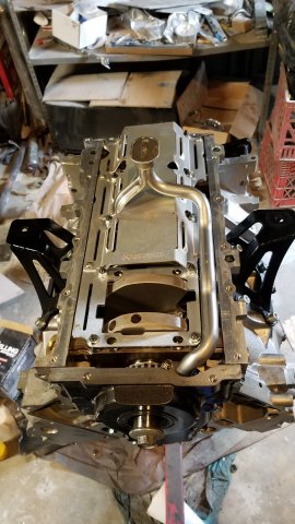
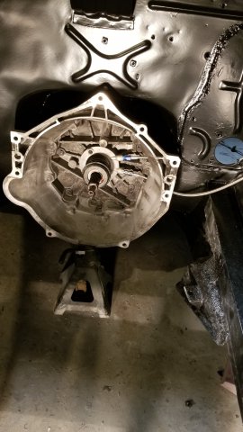
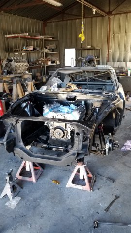
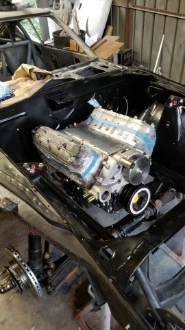
Improved Racing crank scraper and windage tray: AN adapter on clutch slave: aaandd MOTOR IS IN!!!! Now it's time to start fighting the rusted jam nuts on the steering rack. Will probably be a job for the grinder... -
'77 280z aka Project Tetanus (LS6 383, T56)
SH4DY replied to SH4DY's topic in S30 Series - 240z, 260z, 280z
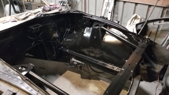
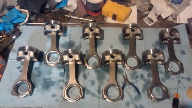
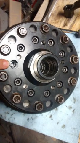
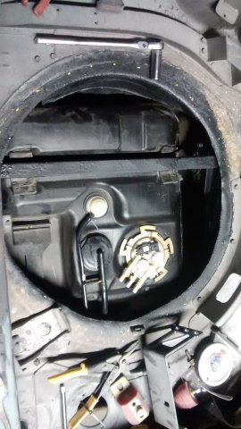
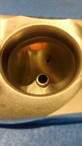
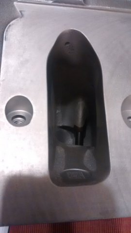
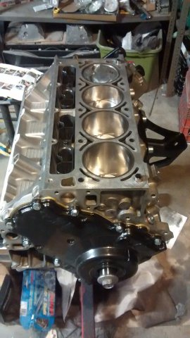
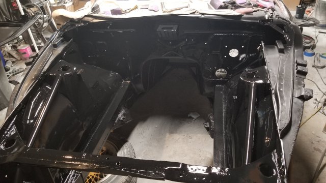
Some updates. Progress has been slow in the winter months but its still coming along. MFactory LSD: F Body fuel tank installed: Engine bay is done: Motor is together: K1 lightweight rods, Wiseco pistons, Wagner CNC'ed 799's w/ Ti Valves (should flow 320+ CFM): -
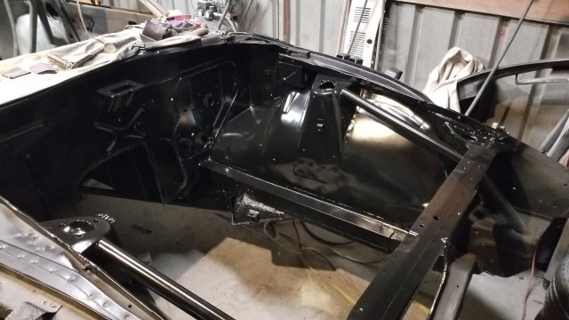
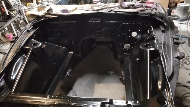
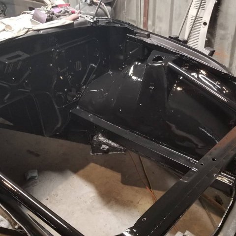
NOT rattle cans. Because of some extenuating circumstances (I bought a house) I was recently forced to ramp up some parts of my project in order to get the car movable to the new location. Part of the dilemma was having an assembled LS6 on an engine stand without a great way to move it. So, I decided to finish up the engine bay (didn't want to paint with motor installed) so I could install the motor/trans for ease of transport. I had done quite a bit of research on engine bay paints and auto paints in general and kept coming back to the Rusto jobs for a few reasons: Ease of touch ups: this car is going to be a driver, which means turning wrenches and wear and tear so there are bound to be scuff/ scratches. Cost: ties into the above but it was also going to be $150 just in materials for the engine bay using the same paint I had planned on doing on the body. Durability: When done properly, I keep reading that the proper Rusto mix can be as hard as tractor paint (read: tough as nails). Current conditions: It's cold here. Full winter mode which doesn't play well will most automotive pants (typically need 60*+). It was 55* in the garage when I sprayed the bay (with the help of a space heater) and hasn't been above 45 degrees in the past week and a half. So, I elected to use the 8:4:1 method. 8 Parts paint (Rustoleum Satin Black), 4 parts reducer(Duplicolor BG906), 1 part hardener (Omni MH202). Hardener was the most expensive part by far ($40/pint) but I've got a bunch left over so that's a plus. Applied with a good old HF HPLV $14.95 spray gun @ 40psi at the gun First pictures are after the second coat was applied and still wet. After about an hour: It look a solid 30-45 minutes to flash in between coats (again, cold). After 24 hours it wasn't fingernail hard but a week later it's just as hard as the factory paint on my Tahoe. I have enough left to do the interior, but I'm not sure if I'll do the exterior in it (wouldn't be black. Maybe the dark gray). Anyway, we'll see how it holds up trying to get the motor in and I'l report back.
- 1 reply
-
- 1
-

-
Has anyone tried to install 180 degree headers?
SH4DY replied to M_Dragan's topic in Gen III & IV Chevy V8Z Tech Board
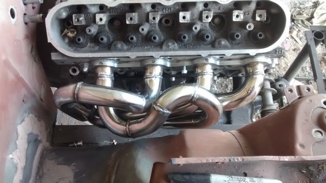
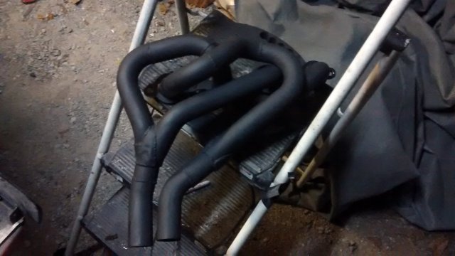
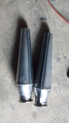
That was my initial plan (180* headers) but incorporating tri-y's and reverse megaphone collectors. I have the top part of the tri-y's done and the collectors (1-5/8" to 1-3/4" to 2.5" collector entry iirc - I haven't messed with them since the summer). I have room between the pan the subframe but I'm still on the fence about actually doing the cross over. It's at least 3' of additional piping. I kept the piping relatively small to help keep the velocity up but now I think with the megaphones and a good x pipe I can maximize the curve/ move it to the right (cam should make steam to 7,500). In hindsight, if I knew I was ditching the crossover I would have gone 1-3/4" -> 1-7/8" step. It's an 11.0:1 Gen 3 LS (383 stroker) with ITB's. -
Just to update: WHP advised me to try to torque the other stub axle per FSM specs and see if it would fail as well. And it did. Except I realized that my wrench only goes up to 150 lbs/ft so the initial failure was also at less torque than I thought. Anyway, this one didn't fail as spectacularly: I torqued to 150, then tried the hub resistance in 1/4 turn increments. On the 3rd or 4th try, the resistance fell of significantly and I thought the threads had stripped. Nope, it just split about half way into the nut so it was still partially threaded. They are supposed to be making a new batch and shipping me some.
-
I agree. Next time around if there isn't any in/out play at 180lb/ft I'm going to let it ride.
