-
Posts
112 -
Joined
-
Last visited
Content Type
Profiles
Forums
Blogs
Events
Gallery
Downloads
Store
Everything posted by Jonas240z
-
Yes my swap is a 350 sbc with an HEI. That's what i thought #1 wire was (green-white) but then for whatever reason the schematic on the book says to connect #10 (starter solenoid) to #1 wire. I'm thinking this is a mistake correct? Since in the later pages it states NOT to connect #10 to the fuel pump, which essentialy is #1 wire. Am i correct then? so the Black-yellow wire does not connect to anything other than the starter solenoid right? Thanks for the help i appreciate it
-
Im doing the wiring on my 240z V8 swap, i searched for an answer but no luck. So here it goes. I made a quick sketch of the wiring on the JTR manual. I got a few questions with this. First of where does the green-white wire hook up to? that wire was mentioned on the previos page on the manual but it just says attach to the fuel pump wiring. Ok fair enough, so where is that wire on the schematic? Does it splice into the GREEN fuel pump wire? Then it tells me to run a wire from the black-yellow (10) wire that powers the starter solenoid to NUMBER 1 wire? So my questions is what is the #1 WIRE? where did it come from? what color? And then the manual says NOT to connect the wire that operates the starter solenoid to the fuel pump. Ok so connecting #10 wire to #1 wire essentialy does this. Since #1 is connected to #2 wire (fuel pump). So what am i reading wrong? Is it a contradiction? All i want to know is where do i hook up the green-white wire to, where do i hook up that Splice from the black-yellow wire (starter) to? Finally the manual says to cut the GREEN fuel pump wire on the passenger footwell. So does it mean cut it and run the wire to the fuel safety swith, or splice the GREEN wire? As always i appeciate the help! V8 WIRE.bmp
-
Got a set of DCOE 45's for sale complete kit, came out of running car. PM or txt 714-293-0036 if interested, John.
-
-
-

Rear Disk brake conversion problem
Jonas240z replied to Jonas240z's topic in Brakes, Wheels, Suspension and Chassis
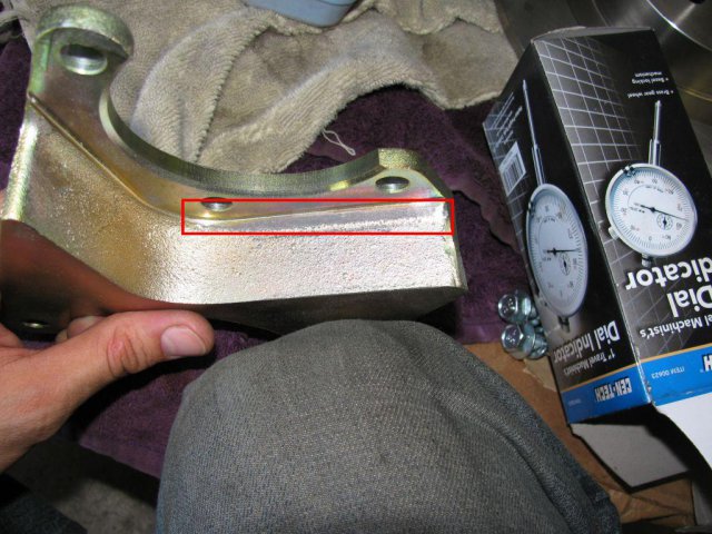
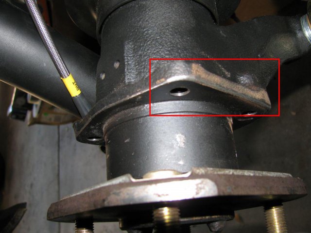
Here are the pics of the areas i had to ground off to make it seat properly. I don't know if the mount casting was out of spec or the defect came from the strut. I ended up grinding down both of them just in case. I hope this helps someone that might encounter the same problem. Thanks for the help from all of you! -

Rear Disk brake conversion problem
Jonas240z replied to Jonas240z's topic in Brakes, Wheels, Suspension and Chassis
Found the problem...thankfully the stub axle, rotor and bracket were all in good shape. The problem was a 1/16 in. interferance between the MM mount and the strut "mounting point, which in turn didn't let the bracket seat properly. I just grounded the portion down, now it fits like a glove. I have pictures of this to show but i'm at work right now. I really appreciate all the help from everyone here. Thank you! -

Rear Disk brake conversion problem
Jonas240z replied to Jonas240z's topic in Brakes, Wheels, Suspension and Chassis
They are MM brakets. I thought the MM were fully machined pieces but i guess not. I got them directly from them, the one on the left does not look like that when it's mounted and the caliper fits. A quick inspection/comparison between left and right mounts left me with more questions since both brakets are the same (one right one left) with no visual differance. I'll inspect them more closely tomorrow. It's hard to think the stub axle or strut mounting point is off. So something is not right. -

Rear Disk brake conversion problem
Jonas240z replied to Jonas240z's topic in Brakes, Wheels, Suspension and Chassis
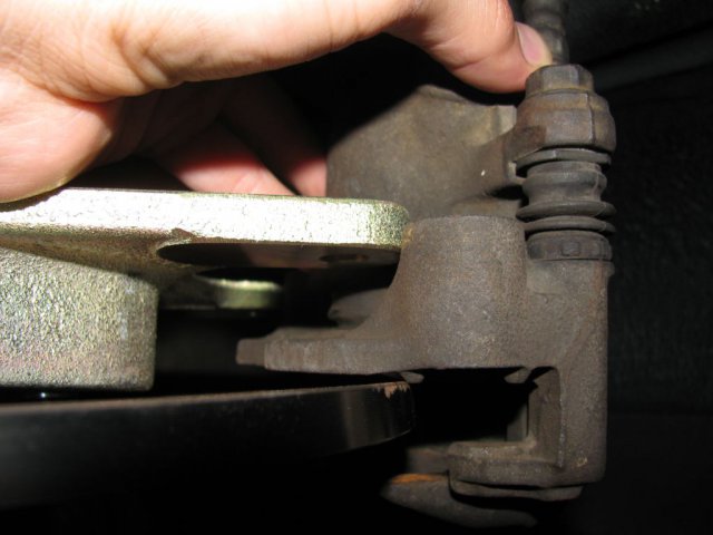
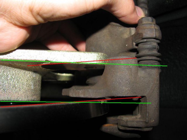
I think i found the problem or at least why it does not go on. I tried to mount the Left side and it went on without a problem, so obviously there is something wrong on the Right side. As you can see on the pictures below, things just don't line up. Why? i really don't know. All surfaces are clean, inspected the bracket and compared to the Left side and they are both the same. Rotors are not warped. So again, i'm just getting more frustrated the more i find. By the way all bearings where replaced and studs as well. Any clues? -

Rear Disk brake conversion problem
Jonas240z replied to Jonas240z's topic in Brakes, Wheels, Suspension and Chassis
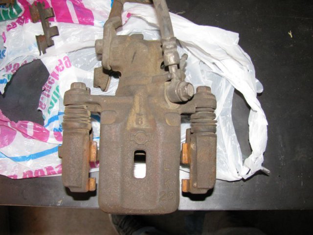
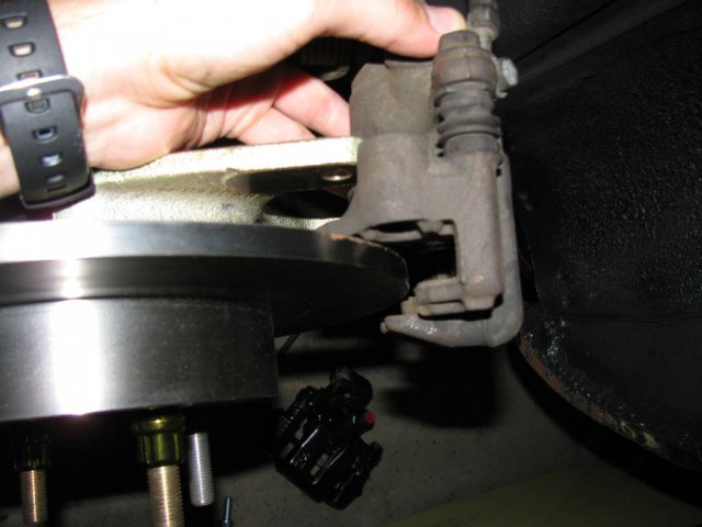
AS 19752802+2 said, the real problem is the space between the MM mount and the rotor. The caliper won't fit into place since the mounting "ears" on the caliper are thicker than the space between the braket and rotor. The Mounts are on the correct side and torqued down to spec. The top picture is for reference to show the calipers i got. The bottom picture shows how the caliper does not fit between this space. It will only fit if it was machined down. That's why i'm puzzled? Any ideas? does anyone have dimentions or pictures to compare? Thanks again. -

Rear Disk brake conversion problem
Jonas240z replied to Jonas240z's topic in Brakes, Wheels, Suspension and Chassis
Any clue guys? i'm really frustrated because everything seams to be in order but it just won't fit in place. All my parts are the ones supposed to be used on this coversion jet for some reason it wont fit; does someone have measurement or a picture to show the way its supposed to be? My rotors are brembo, for a '84 300zx NA. Calipers from a junk yard '89 240sx. Kit from modern motorsports. -
Hi guys; I got the modern motorsports rear disk coversion kit for my 240z minus the disk brakes(i had some already. I went to mount the kit and everything was good until i tried fitting the calipers. As you can see by the pictures the caliper mounting points are to thick for the space between the disk and MM mount. The measurements are as follows; Caliper mounting thickness 1 1/4" Space available between disk and MM mount 1 1/16" Disk size 11 3/8 diameter, 1 7/16 hat thickness, 3/8 thick rotor. What am i doing wrong? do i have the correct parts? Thanks for the help in advanced.
-

MSA 240z Rear Sway Bar
Jonas240z replied to Jonas240z's topic in Brakes, Wheels, Suspension and Chassis
Thanks for the info, i really wish someone has a picture available. I also have an old swaybar that goes behind the diff cover. The only thing is that the bushings are crap now. I don't know what brand or kind that bar is, so i don't know where to get those bushings. Thanks for the help. -
I purchaced a set of sway bars from MSA. It comes with instruction and all but i really don't see how the rear sway bar will be mounted. Does anyone here have a picture of it mounted already? I also have 300zx CV's and R200, i don't know if it makes a differance? Thanks
-

OBX Differential Inspection and Installation
Jonas240z replied to TrumpetRhapsody's topic in Drivetrain
Thank you for the help. I think my carrier bearing well preloaded since it was a pretty snug fit to get the OBX unit in. I was just wondering if i just take measurements of the stock shims and the go purchase the next step up from that measurement on the left shim. Will the differance between the two move it just that much to the left? Say mine is .255 and the next one up is .260, will that open the backlash .005? Thanks again, you guys are great help! -

OBX Differential Inspection and Installation
Jonas240z replied to TrumpetRhapsody's topic in Drivetrain
Just finished installing the OBX unit on my R200, torqued everything to spec and now backlash is .002 only. It turns smootly but i'm concerned about the smaller lash. Is it ok to run it like that or do i have to adjust it? If so how do i know what size spacer to use to adjust it? Thanks -
-
I finished up moving up the trans to the right a little more and the shifter barely fits . It will still need to be trimed. Also i placed a laser at the outputshaft and it still does not line up perfectly with the rear end flange. It's about 3/16 to 1/4 inch of center. Is that acceptable? or do i keep moving it more? I already trimmed the trans crossmember mounting hole a little. Thanks for the help guys
-
Hi guys; As the title says im looking for a 280z mustache bar and front differential mount (not the rubber mount). So if anyone outhere has a spare one send me a PM and we can go from there. I just need those to complete my R200 swap! Thanks!
-
I appreciate the help form all of you guys. I think the motor mounts are in the right position as show on the pic above. I didn't know the tranny mount was offset as well. I'll also take a look at it. The drive shaft angle is off still so i'll do what i need to make it work. Thanks again!

