OhBilly
-
Posts
114 -
Joined
-
Last visited
Content Type
Profiles
Forums
Blogs
Events
Gallery
Downloads
Store
Everything posted by OhBilly
-
It's kind of hard to tell from the sound in the video, but it does sound like it is missing. Have you pulled your plugs out and read them recently? Compression test? Head gasket?
-
280z Turbo intake piping while keeping AC question
OhBilly replied to Milenko2121's topic in Turbo / Supercharger
Are you using the stock intake parts and/or ECU, or are you using aftermarket stuff? A guy named Ben is trying to route his intake piping (with the AFM) while using AC in this thread here: http://forums.hybridz.org/topic/111736-ready-to-blow-my-brains-out/ He has a photo posted that shows some of the trouble he is having. Much of the rest of the thread has been wasted on arguing the semantics of BOVs and various other stock pneumatic valves. Take from it what you can. -
It's U6, the communications chip. It's over by the DB9 connector.
-
The only reason I am bitching at you is because you falsely accused me of presenting misinformation. I have restated my case and have backed it up with facts, even using information and advice you have given yourself dozens, if not hundreds of times. You haven't bothered to explain why you think the information I gave is bogus, likely because it isn't and you would have to contradict yourself if you did. Instead you just yammer on about how annoying we are and refuse to acknowledge that you have falsely accused me of giving out lame advice. You speak about being an adult but your actions are more in line with that of a 4th grade playground bully trying to get attention. Mature adults are willing to admit when they are wrong and they certainly don't hide behind an "IGNORE" wall so they don't have to deal with reality smacking them in the face. Have fun hiding from the grownups! ** EDIT: I see now you've gone back and edited your post #33 to haphazardly refute what I wrote in #35 after the fact. Classy!
-
I had the same trouble for a while and I finally found that I had some bad solder connections on the MAX232.
-
What, you want me to call it a compressor bypass valve (CBV) instead of a BOV because of how it is vented? Fine. I use the term BOV because that is what the majority of "car guys" call them. Whether it is vented to atmosphere or somewhere else, most people still call it a BOV. Second, the OP is not using a turbo intake manifold, he's using an N42. He does not have a stock VCV, he has (presumably) some sort of aftermarket BOV/CBV. He doesn't want to vent it to atmosphere, so where should he vent it? Since it's metered air, how about venting it back somewhere between the AFM and turbo inlet? Seems reasonable to me, and based upon reading many posts about this same subject (many of them written by you), this seems to be the proper way to set up an AFTERMARKET BOV/CBV. I'm not sure how this is spreading misinformation. And I did not quote you out of context. The context was about how to properly set up his BOV. How is that out of context to your elsewhere post? Sure, the stock VCV works well, with all those benefits you've told us about, and if he had it, yes, he should keep the stock system as is. But he doesn't have that stuff! If I am giving him bad advice on how to set up an aftermarket BOV/CBV for use with his N42 intake, what should he do instead? ** Edited for bad grammar **
-
I have read it somewhere, in fact I've read it pretty much everywhere. And believe it or not, you just posted a link above about people quoting you on it. Correct me if I'm wrong, but did you not type this in your first link: Tony D said (emphasis mine): "Compressor Bypass Valve. Often referred to, and set up incorrectly as a "BOV" the compressor bypass valve is lifted open and provides a path around the turbocharger to the intake's throttle body so as to remove any parasitic forces on the compressor side of the turbosupercharger to aid in spooling. On lift throttle it will open, venting excess boost either to atmosphere,or back to the inlet of the turbosupercharger as well as operate the turbo at a given minimum flow rate through the compressor similar to a Pop-Off-Valve." Alter it from the stock engineered location? He's not using the stock valve, nor the stock intake. If he were I doubt we would be having this conversation. As far as giving logical reasons for something, I think I'll leave that up to you. I'm not sure why you are coming down on me for giving the guy reasonable advice, advice that you (and the rest of the automotive engineering world) presumably agree with since you've stated it as well. You are very good at explaining complex subjects and to the right audience, that's all fine and dandy. But many people just don't have the time, money or gumption to get into it as you would like them to. Poor Ben here is just trying to figure out the basics and you are throwing flow theory and electrical engineering at him. Ridiculing him for not understanding it like you isn't helping him out, regardless of what you'd like to believe. Help the guy to get his car going so he can drive the damn thing.
-
If you are going to recirc your BOV, it should recirc back into your intake, as in pre-turbo.
-
If you call these guys up they might be able to make you some (or have some) with longer leg lengths: http://www.siliconeintakes.com Most all of their listed products have associated dimensions so you should be able to find the information you need. Good luck.
-
Combine the above two posts and you've pretty much got it. The key is that your stock ECU wants to see a narrowband signal, so you'll need to get a wideband setup that can output a narrowband signal. The Innovate stuff does that and I'm sure the AEM stuff does as well, and probably most others. Many people have had trouble with the Innovate products so it may be best to go with something different. And yes, you'll likely want to add an additional bung farther downstream from the turbo. If you do that, make sure the bung doesn't face downward so the sensor doesn't get affected by any condensate. To be safe, have the bung installed facing as much upward as you can, but make sure you account for any sensor clearance issues with the body of your car.
-
The IC should work fine as long as you can get it to fit (I could be wrong, but I think 25" is about as long as you can squeeze in there). The piping kit should be most all you need but you may find you'll need an additional length here or there, or a slightly different bend here or there. The thing with IC pipe routing is that you really need to get the pipes in hand and start fabbing it up. For boost adjustment there are a couple of easy and cheap routes you can take. The old standby is to make the length of the actuator rod adjustable. On mine I cut the actuator rod in half and then cut off about a 1/2 inch section of one of the pieces. Then I threaded each rod section and coupled them together with, wait for it.... a coupler. I don't remember the diameter of the actuator rod but I think it was about 1/4 inch, so I tapped it 1/4-20 IIRC. Another boost control option is to build a check ball and spring valve, aka the "Grainger" valve. I built one and never used it because I decided to go with the adjustable rod length method above. All the parts you need for it can be found at your local Ace or Menards or whatever. For your BOV mounting flange, it's easy to just get one of the generic straight ones you can find on ebay. I replied to your other post on this subject yesterday and posted a pic of mine. The Bell FMU I'm sure will work fine but I don't have any experience with it.
-
Those SU carbs can perform quite nicely if you take the time to learn about them. A good quality rebuild can do wonders for them. And no, converting it back to fuel injection is not going to be a simple plug-n-play operation. Unless you plan to spend some significant time and money to do it right, you're better off to stick with the SUs. My two cents. If you haven't researched those SU carbs yet, here is a good resource: http://www.ztherapy.com/ Good luck.
-
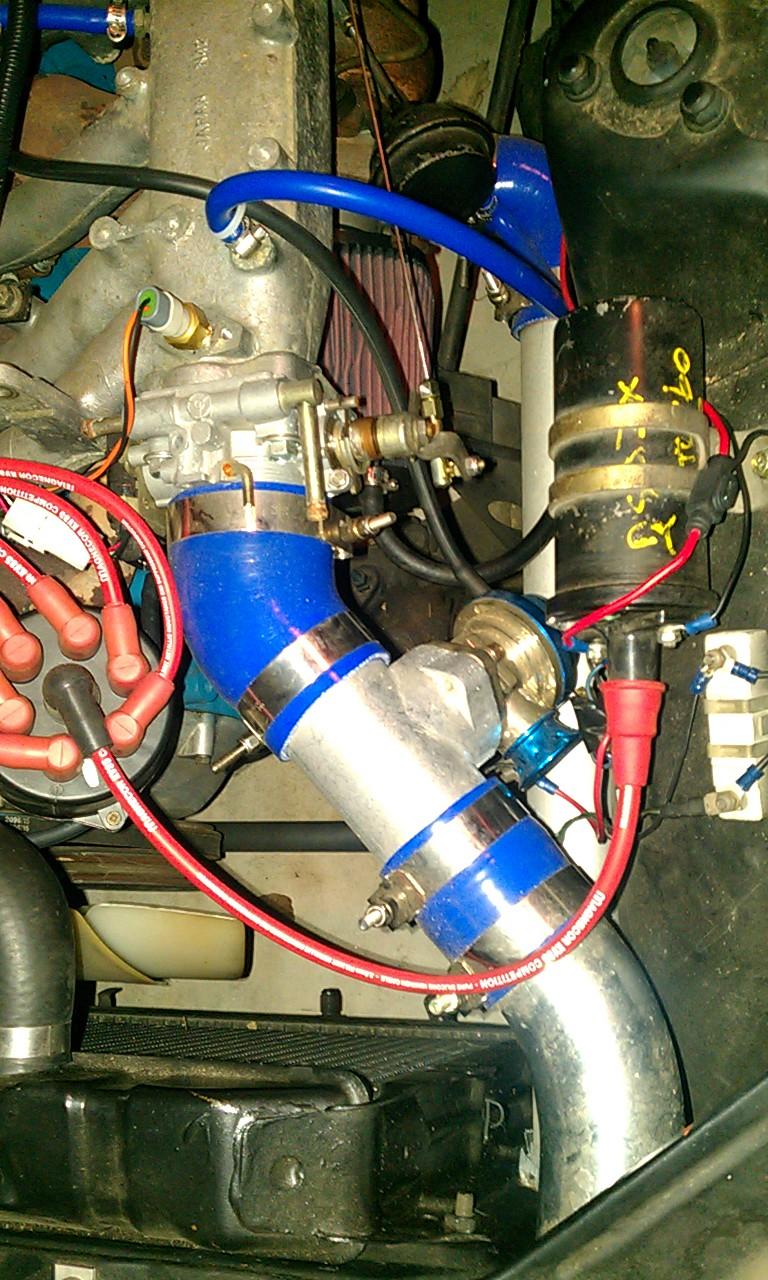
It's not a great photo, but here is a shot of my Greddy RS knockoff mounted right before the TB. It's not mounted directly to an elbow, but right in between the elbow connected to the TB and another curved aluminum piece going out through the radiator support. The valve is mounted to a generic ebay special flange.

-
I built my MS1 V3 MSnS setup pretty much directly from the V3 build manual. Build it up to use a Hall sensor, and follow the directions on "How to Megasquirt your 280ZX turbo" from the DIY site: http://www.diyautotune.com/tech_articles/how_to_megasquirt_your_280zx_turbo.htm I followed that article to a tee and everything worked just like it should. If you haven't got there yet, take extra extra extra care when soldering on the tiny little transistors (i.e. Q15, etc). I learned the hard way that it's very easy to short out the leads with just the tiniest amount of excess solder. My bunked solder job luckily didn't hurt anything, but it made one bank of injectors inoperable and caused me weeks of grief trying to figure out the problem. Yes, you can download the firmware and install it without modifying the board. EDIT: While you are building the board there are a few modifications you might consider doing while you are at it: http://forums.hybridz.org/topic/94634-non-standard-board-mods-that-you-should-do-from-the-beginning/ I had the same problems letitsnow had and I fixed them using his advice on that thread. I didn't do anything in the paragraph where he talks about the 47uF cap, but I did do his steps 1, 2 and 3 and I soldered the .1uF cap across pin 2 and pin 6 on the backside of the CPU socket.
-
You probably have your wideband configuration set wrong in MS. You'll need to open up the configurator and dive into the settings.ini file to set it correctly. At least that's how it's done in Megatune, not so sure about TunerStudio.
-
It's unclear what you mean by "I set the distributor to 0 using an offset of 60..." Does this mean that you set Megasquirt cranking advance to 0, then cranked it over while strobing it, and it strobed on 0 at an offset of 60? If so, that's a good sign. But once you get it running, you'll also want to strobe it to verify accurate timing. Set it to fixed timing at somewhere around 20* BTDC and get her started and idling. Then strobe it to verify it's actually firing at 20*. I think the FPR bleeding pressure through the return line is normal, at least it is on mine.
-
What wideband are you running (your link isn't working so I couldn't check)? It looks like you're getting some noise on the wideband line but it may be that I don't have the parameters in Megalogviewer correct for your setup. Your AFR leaning out is expected because your afterstart and warmup enrichments will taper as the car warms up. I don't see anything in the datalog to suggest a fuel supply issue. The kickback issue: After you got the car started did you verify your actual timing and the timing reported by MS correspond? What is your cranking advance? The neighborhood of 10* BTDC should work pretty well. Do you have a priming pulse set to something other than zero? If so, your initial cranking to prime it with oil could have dumped a fair amount of fuel in the cylinders. If that's the case, maybe the kickback was actually a bit of hydrolock....? I'm not sure how the stock FPR works, but unless it has a built in check valve you will bleed pressure pretty quickly through the return line. I have an Aeromotive FPR and mine behaves pretty much exactly like you've described.
-
Emergency Electrical Power Shutoff Location
OhBilly replied to RebekahsZ's topic in Ignition and Electrical
For location, you will typically see them just inside the driver's window, usually mounted on the A-pillar. Remember that if an accident occurs, YOU also want easy access to the emergency shut-off. Another thing to consider is that an emergency worker's first priority will be to get you out of the car if necessary, and the drivers window is where they'll likely be going first. Plus, that's where an emergency worker would be looking for it. EDIT: Just wanted to add that you could also have the desire to activate the shut-off while still driving on track. It doesn't take a crash to get a good fire started. In my opinion having the shut-off within driver's reach is the way to go. -
Turn signal turns on with parking light switch
OhBilly replied to OhBilly's topic in Ignition and Electrical
Problems resolved. Here's a quick summary of the problems and eventual solutions in the event this thread might help someone else hunt down their electrical gremlins. Problem: Headlights would not turn on despite good fuses and a cleaning of the electrical contacts inside the combination switch. Solution: When I originally cleaned up the contacts, when I put the switch back together I flubbed it up. The little electrical contacts rocker back and forth with movement of the switch, and these rockers are held in place at their pivot points by being cradled between a metal piece that forms one of the contacts. My pivot ended up being too tight and slightly pinched the rocker, not allowing it to travel its full range inside the switch. I simply loosened up the squeeze on the rockering contact and now the lights work fine. Problem: When turning on the parking lights, the RH turn signal indicator on the dash would light up solid and the front RH combination bulb would not. All other parking and turn signal lights worked fine. Solution: Turned out the RF bulb socket ground was badly corroded and essentially open. The electrical current, instead of going to ground and lighting up the parking light filament, was back-feeding through the turn signal filament and into the indicator light on the dash which has it's own ground, hence why it lit up instead. I fixed it by cleaning up the socket and re-soldering the ground. Miles, thanks for your help. You nailed it on the headlight problem. -
MS1 Extra works with either high or low impedance injectors. I'm running MS1 V3.0 with 440cc low impedance injectors utilizing the PWM circuitry built-in to the board and it works well. Moby's writeup has some very good information in there but he was running a 2.2 board at that time, so some of the stuff need not apply (like the resistor pack stuff and utilizing an HEI module to fire your coil). DIYAutoTune has a very good writeup on installing MS1 V3.0 (or MS2) on a 280ZX turbo right here: http://www.diyautotune.com/tech_articles/how_to_megasquirt_your_280zx_turbo.htm I followed the DIY install article exactly as it is written and it works quite nicely. MS1 V3.0 has nearly all the capability of MS2. The main noticeable difference is the capability of MS2 to control your injectors to a higher resolution (MS1 has .1ms resolution, MS2 has .01ms resolution). This difference will be most apparent in the idle quality of installs using relatively large injectors (your 440s would fall into that category). With MS1 you will be able to get a nice and smooth idle but it will probably be a little richer than you'd like, probably around the 11-12 AFR range, and you'll probably have some visible exhaust smoke. With MS2 you'd be able to get your idle AFR right where you want it, around the 14-15 AFR range with less visible exhaust. At all other running conditions the difference in injector resolution won't be too noticeable, both will work great but MS2 will be a touch smoother. If you can afford to go with MS2, do it. Far more people on this forum are using MS2 which means you'd have more support using that platform. But if you get MS1 V3.0 you can always upgrade to MS2 later for about $100 or so.
-
The price difference of a 3.0 kit vs. a 2.2 kit is $50 at DIYAutoTune. If you don't have that extra $50 now, I would hold off on buying until you do. 3.0 is much more refined and you'll have way more support from users here, and elsewhere, that also use the 3.0 board. Looking at it another way, you'll easily save the $50 price difference because you'd likely spend substantially more than that trying to get your car to run reliably on the 2.2 board!
-
Regarding your jumpers on the board, I just talked to one of our electrical engineers here. He said to make sure the jumpers get routed away from as many electrical components as possible. A good route is to come off the TIP125s and go up, running the wires along the upper edge of the case between the case wall and the screws/nuts securing all the transistors to the heat sink. When the wires get to the Q16 area, route them down along the back edge of the DB37 connector to your IAC jumpers. Just avoid running the wires over the top of other components on the board because that can cause unwanted noise as well.
-
It's really good to know that the jitter can be dealt with. Today I am going to separate out the +12V feed to the flyback circuit per letitsnows "non-standard board mods" thread. It looks like it will be really easy to do since I have a number of spare jumper locations available on the board (IAC1A, IAC1B, IAC2A and IAC2B) with corresponding terminal block locations on the relay board (S1, S1, S3 and S4). The whole thing shouldn't take more than 15 minutes. I don't know when I'll get to test it but I'll keep you posted. For some reason my fuel pump quit working a few days ago. I need to crawl under the back of the car and check the wiring. It's always something.... Good luck Mike.
-
Hmmm. Since you have experience with a few other installs that weren't jittery, I'll assume you are correct that it isn't that way by nature. My MS install is the only MS experience I have and low and behold, my car behaves exactly like you state above. Just holding a constant speed, my car is definitely jittery. Under any kind of load, it doesn't jitter. assumed this was just normal MS behavior. Regarding your fuel system stuff, I doubt that is causing much trouble since your car and my car I would say are behaving pretty much the same. Sounds like we could both stand doing some "non-standard board mods" to see what happens. Other than that, it sounds like going with the inline injector resistors are the way to go (and turn PWM off).
-
I'm not sure if I'm supposed to be happy or sad for you. I quick-looked your datalog and it didn't look too bad to me. I get voltage spikes about the same as you do. If you really want to smooth it out you're likely going to have to do the separate 12V feed to the injectors like letitsnow described in the "non-standard board mods" thread. That mod is in my future as well, but right now it's not a major priority. I get the impression that you have expectations of your MS box controlling things as well as an OE ECU. The unfortunate but truthful reply is that it just isn't going to do that. Yes, you can make it work pretty damn well considering what it cost, but just try to remember that at its roots it's a hobbyist computer. OE ECUs have thousands of hours of engineering behind them, and OE wiring harnesses are the same way. I'd suggest the next time you go out and drive it, keep the laptop lid closed and just try to enjoy it a little bit. Don't peer too hard at the data, trying to get every glitch and quirkiness to disappear. Don't be the dog that chases his own tail until he collapses from exhaustion Cheers.