toolman
-
Posts
518 -
Joined
-
Last visited
-
Days Won
7
Content Type
Profiles
Forums
Blogs
Events
Gallery
Downloads
Store
Everything posted by toolman
-
Heavy Duty frame rails and connectors
toolman replied to toolman's topic in Gen III & IV Chevy V8Z Tech Board
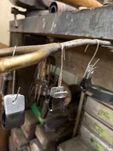
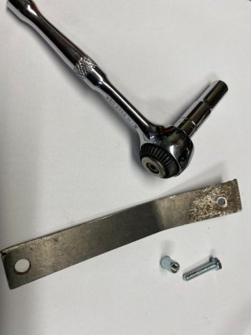
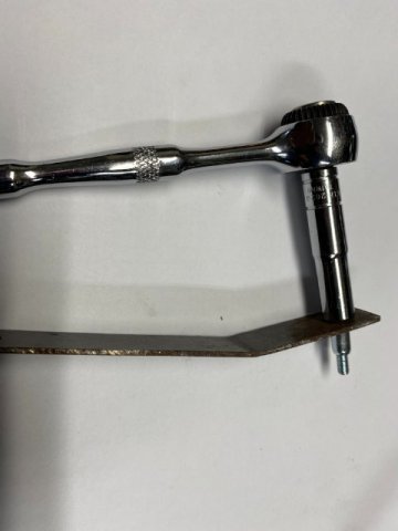
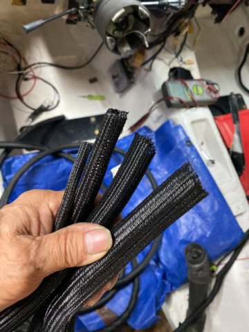
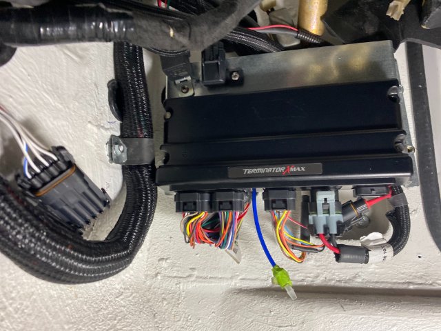
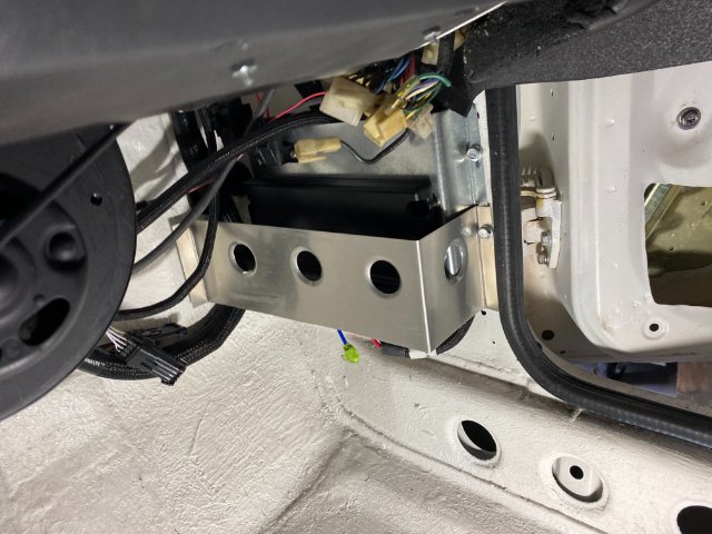
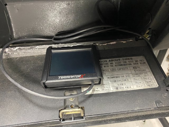
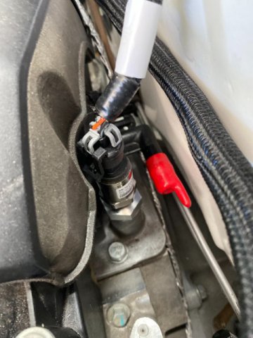
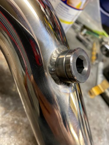
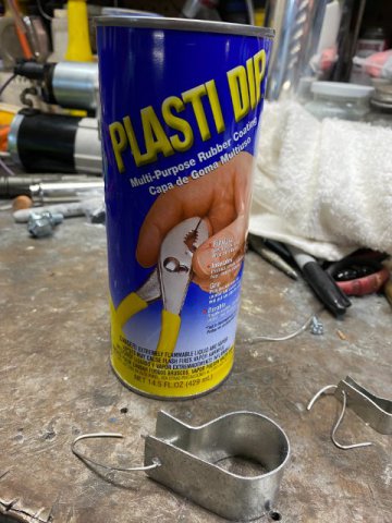
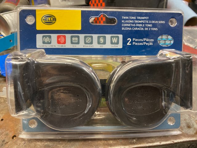
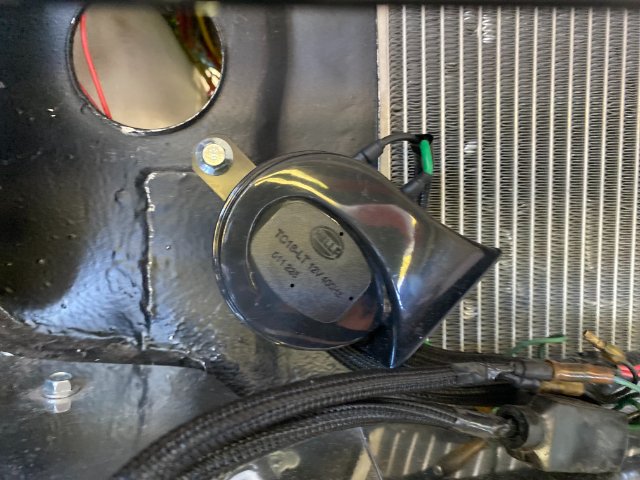
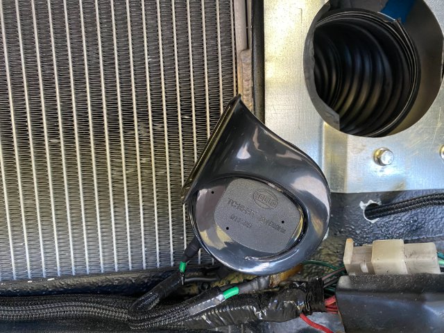
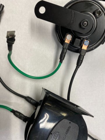
Sorry for the delay in posting, my PC broke down over the week end and tried to fix it. But ended up getting a new one at Costco. Wiring Harness Mounts- Since there were so many different sizes harness mounts necessary, I decided to construct my own. I used 22 gauge steel metal with 3/4" to 1" strips. Plastic Dip which a Black Plastic Protective Cover used to create no-slip handle covers for hand tools. Procedure is slowly dip the items into the can to add the coatings on. It works better by dipping multiple times instead trying to make one heavy coating. I dipped the mounts in about three to four times( allow 30 minutes drying time between coats) to get thick but smooth coatings. Let it dry completely dry for 24 hours before using. I used Metric Nut Inserts to hold the harness mounts and found that some locations were too tight to use the normal Thread Insert Rivet Pliers. So I constructed a simple tool to do this job in "Real Tight Places. Used !/8" x 3/4" x 8" mild steel plate with 1/4" hole drilled in one end. Just inset a 4MM insert insert in the hole and place the right size bolt on the 4MM insert. Then, just tighten the bolt and it will squeeze the nutsert tight. In REAL TIGHT PLACES, you can use a Hand Wrench instead of a ratchet and socket. It takes longer but it will work too. Wiring Harness Looms Previously I used Flexible Plastic Split Opening Wiring Looms but found out these looms would hold water and debris in them. So now, First, Premium Scotch Brand Black Electric Tape was wrapped tightly over the wire harness. Then Alex Tech Split Sleeve Wiring Looms were installed over that. This braided covering is very tear resistant but allow water to drain out. , ALEX TECH SPLIT SLEEVING is sold on Amazon with !/4", 1/2",3/4" and 1" tubing sizes. Note-After cutting the ends off, it is recommended that a mini torch be used to burn the ends slightly to prevent ends from coming apart. The ends can be taped with electrical tape or use Heat Shrink tubing to hold the ends down. I noticed that even factory wiring comes with this type of looms. Holley Terminator Computer Installation The Holley Terminator Computer was installed on the Passenger Side Kick Panel with fabricated mount. Note-Wiring harness Mounting Clamp holding the harness it the firewall. A 1/8" Aluminum Protective Plate was added to bottom area of the computer to prevent damage to the wiring. The Computer Maintenance LED Lights are located on the top of the computer so are still visible in this location. The computer mount was built with 1" clearance for the wiring to allow wiring to go underneath. The Holley 3 1/2" LED Touch Screen Display was stored in the Glove Compartment. It will be used to tune the computer. Holley Universal Oil Pressure Transducer The Factory LS3 Oil Pressure Sender will not function with the Holley Computer so the Holley Oil Pressure Transducer must be utilized. Cost $140 from Amazon. Holley Included the Oxygen Sensor Bung that must be welded in the Front Exhaust pipe after the exhaust manifold. Horn installation- A pair of Hella Toyota Horns ( Amazon $30) Horns were mounted using existing radiator lower mounting bolts, Right side Horn Left side Horn Next-T56 Transmission Electronic Speed Sensor to 240z Manual Speedometer Conversion Kit
-
I tried for a couple of days to reset my password. It said that confirmation would be sent to my email address but I still have not received any emails from this site. I checked even junk mail box ,too. Thanks, Toolman
-
5 Star Rising, I hate to be the bearer of "Bad News" but if your measurements are correct, a proper repair is beyond most home mechanics. I am a ASE Certified Automotive Body and Paint Repairman. Your damage is to great to just slot brackets and achieve proper alignment. I would say your best best is get a repair estimate from a Body Shop in your area. But fixing the car and not damaging the paint job might not not be possible. I hope this advise helps.
-
Heavy Duty frame rails and connectors
toolman replied to toolman's topic in Gen III & IV Chevy V8Z Tech Board
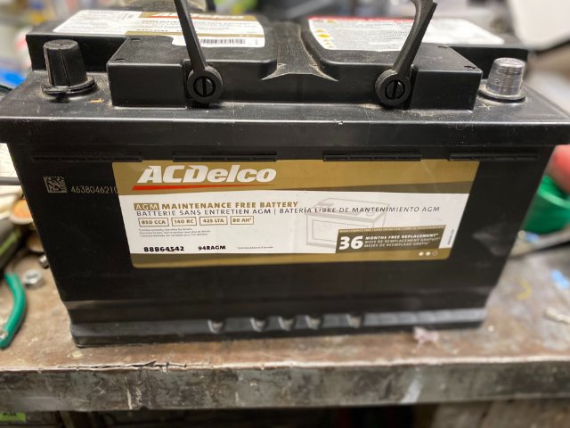
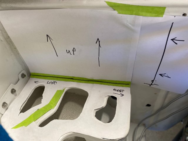
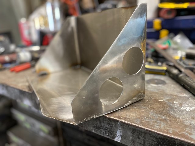
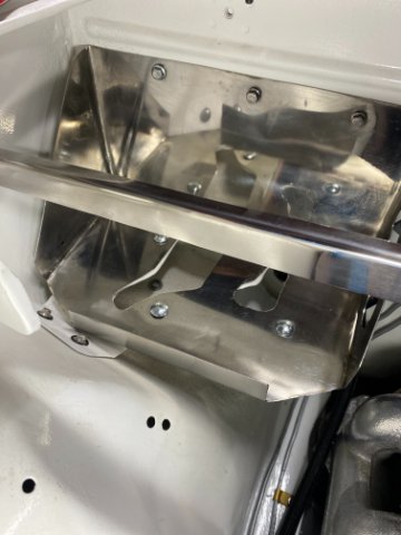
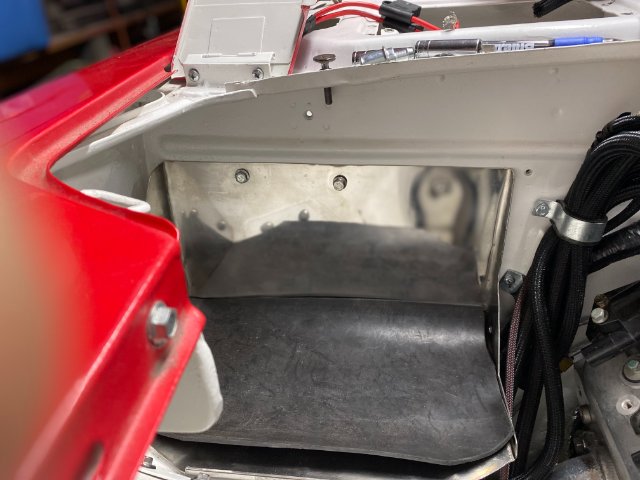
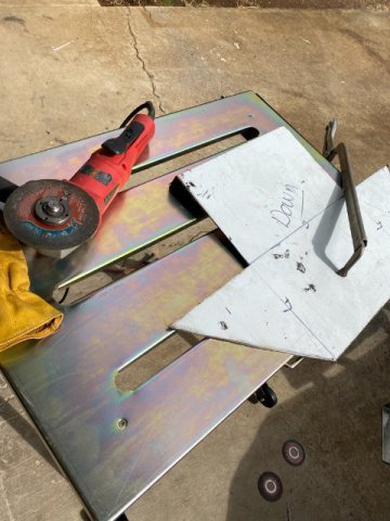
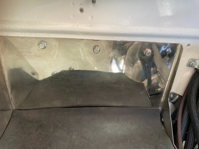
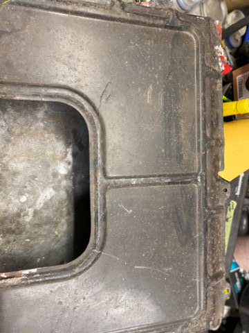
Battery Box Modifications- This is the Delco Replacement Battery for a 2019 Chevrolet Corvette 6.0L LS3. It is a GelCell Battery rated at 900CCA but weighs 49 pounds. Because of its weight and size, I decided to beef up the original Battery Tray. Making a Paper Template of New Battery Tray I decided to construct the Battery Box out of 16 gauge Stainless Steel. Used Right Angle Grinder with cutoff wheel to cut the Stainless Steel. Filing down the sharp edges from cutting. After Bending the Stainless Steel and tack welding the two front corners, the Battery Box looked like this. Front View Added two Holes on side for Improved Appearance. Made a Paper Template to locate the Mounting Holes for the Battery Box. Template taped the Bottom of the Battery Box to locate holes to be drilled. Three 6mm bolt and nuts installed in Firewall to support the Box. A 1/8" steel bar was installed in the window cowl to reinforce the three bolts in the firewall. Four 5/16" Carriage Bolts and nuts secured the Box to existing Battery Tray. The Box was polished with Buffing wheel. Battery Box Version-1 Front View Battery Box with Stainless Steel Hold Down Bolts. Unfortunately, when I tried to put the Delco Battery into the New Battery Box, it would not go in. The Left Side Box Wall prevented the Battery from sliding in. So that Wall had to be removed. Modified Battery Box Version-2 With a 1/4" Rubber Mat on bottom to absorb vibration. Another Angle view of the Battery Box. This Second Version shows no matter how careful you plan something, it can go wrong. So You must be able to adapt and continue. Next-More Wiring to do
-
Heavy Duty frame rails and connectors
toolman replied to toolman's topic in Gen III & IV Chevy V8Z Tech Board
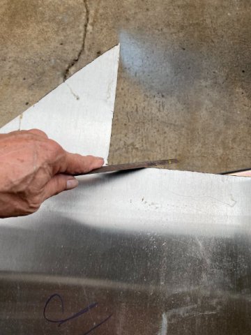
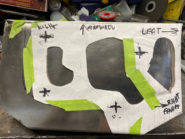
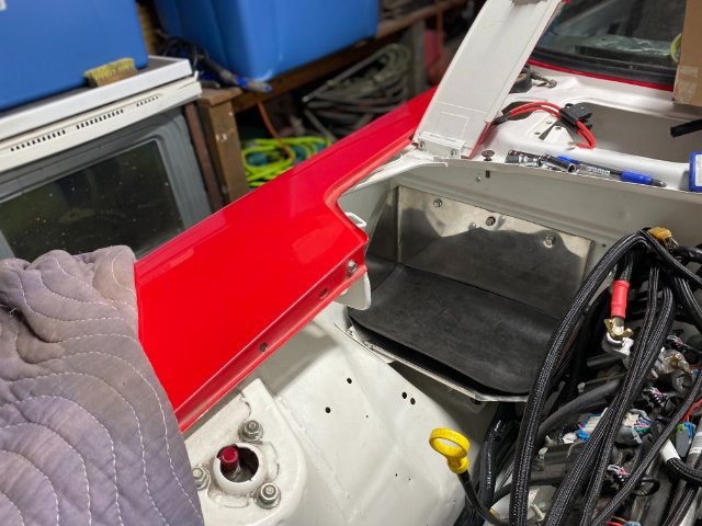
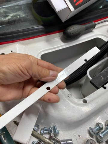
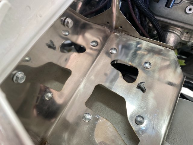
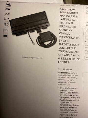
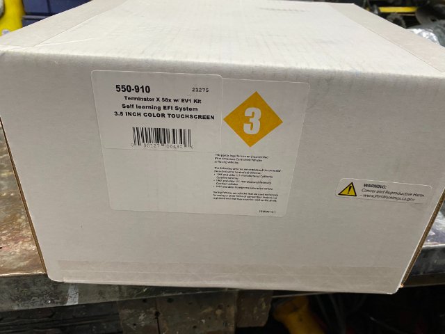
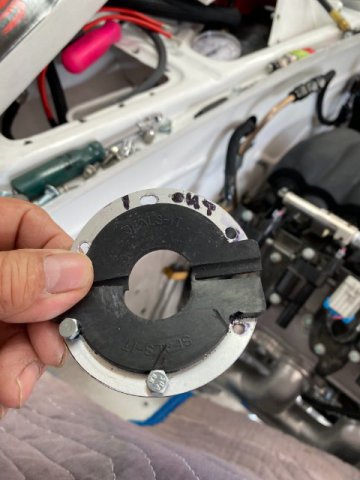
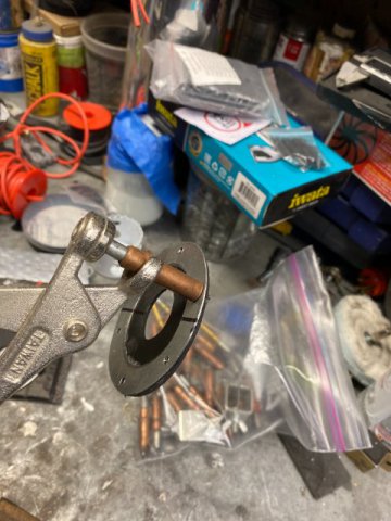
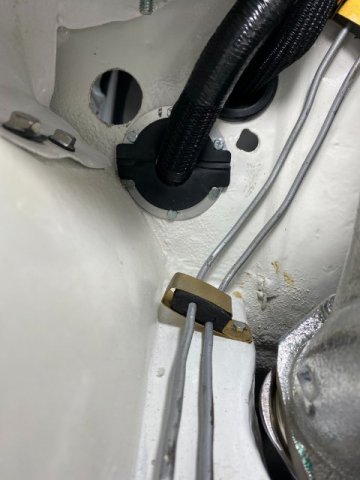
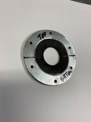
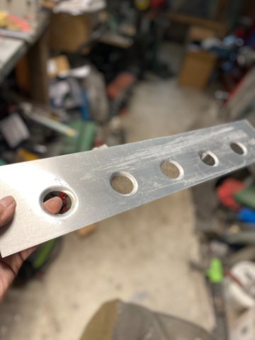
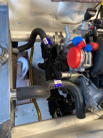
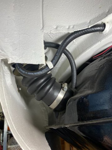
Change of Plans- I must have been a "Good Boy" because my Ungraded Holley Terminator X Max arrived on Christmas Eve. Brand New Holley Terminator X Max# 555550-910 was designed for Late Model LS3 motor with 58 CAM, EV6 Injectors, Drive by Wire Throttle Body and a Remote 3.5 Touch Screen Turner was $1540 from Amazon. I started by laying the Holley harness over the motor and attaching the sensors. Everything pretty much lined up but there were wires which were a little short. But no big deal. A little shifting of harness around and removing the tape on the looms to gain an inch or so. Then,retaping the hareness. With the harness laid out, I could tell the major problem would be getting the harness through the firewall to connect to the computer. The area between the Battery Tray and Firewall was the only place where everything would fit. Local Reconstruction Law did not allow relocating the battery into the rear of the car. Although that location would make harness routing much easier with no battery in the way. Plus, Weight Distribution would be better too. This was a small Area for alot of wiring to pass through. The holes under the battery tray was for the AC Hoses to pass thu. I found this Split-Seal Grommets that was big enough but stll provide good sealing qualities. But they costed $35 each from Amazon. seal Note- The Split-Seal has extra sealing lip at the joint. It provides a little more joint sealing. I also made an additional sheet metal ring to reinforce the seal from the interior side of the seal. The Split Seal and Reinforcing Ring was bolted together with six 4MM bolts and nuts. Cleco Pins were utilized to position the seal while installing. Engine Compartment View-Seal installed with harness going through the Firewall. f Interior View of Split Seal installed. Aluminum Templates with various hole sizes were used to determine correct hole to be drilled in the Firewall. The biggest objects on the harness were the various relays so the hole had to be at least this diameter so the harness could fit thu. In case you need a custom Grommet , this is the procedure to construct one. Cut out 23 gauge sheet metal to create the Outer Frame. Use a razor or knife to make the Round Seal out of 1/8" rubber sheet. . Finish shaping and use Contact Cement to attach Rubber Seal to frame. Then drill six Mounting Holes and cut seal in half. If additional sealing is needed, just make an additional rubber seal on the Interior Side of the seal. Note-It is important to make the Center Sealing Hole slightly smaller to provide a tight fit with harness. For Grommets for other Small Wires, you can use Grommets (from Home Depot). Use the ones made specifically for certain size sheet metal hole. These seals are usually made of for use in sheel metal holes but check to be sure. If you want a tight fit for individual wires, drill slightly larger holes than wire diameter and push wires thu individual holes instead of just slitting the grommets. This method provides tighter sealing fit. Next-Battery Box
-
Heavy Duty frame rails and connectors
toolman replied to toolman's topic in Gen III & IV Chevy V8Z Tech Board
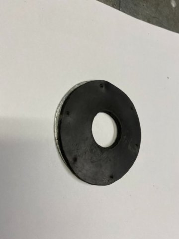
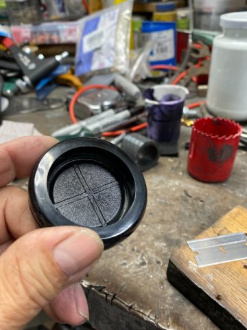
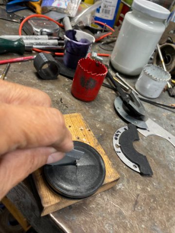
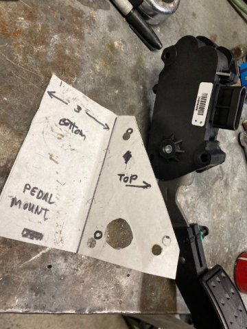
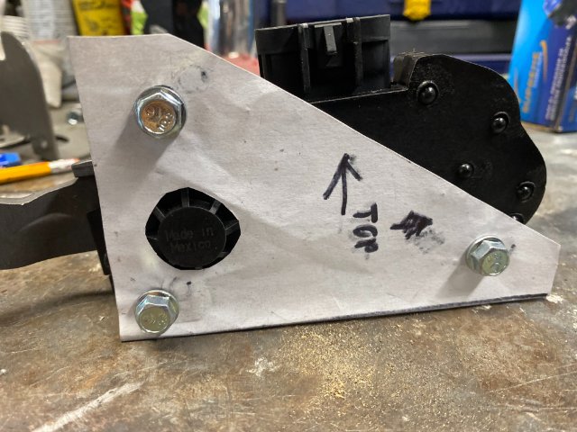
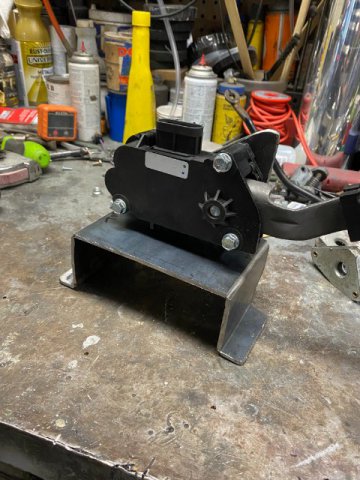
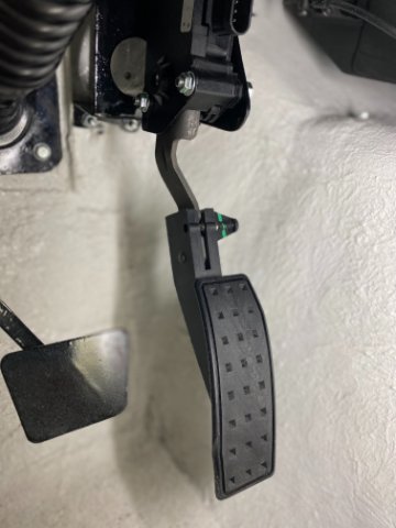
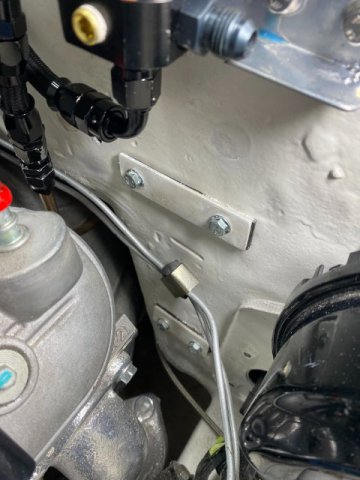
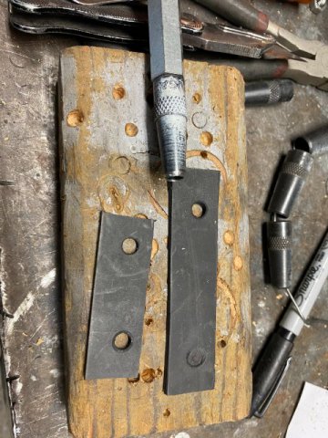
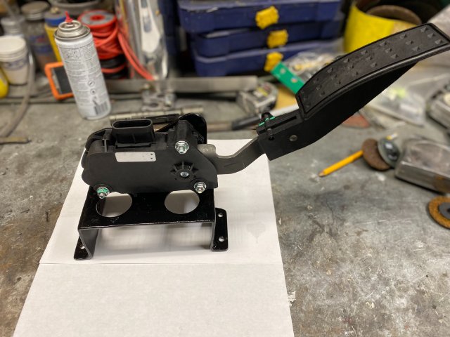
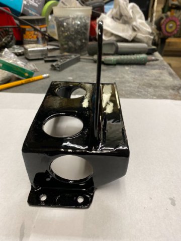
I was planning to post about installing the Holley Terminator X Engine Control Kit but at the last moment I decided to go to a upgraded version of the Holley Kit. So that may take a couple of weeks to arrive because of the Pandemic and Christmas. but there are still plenty work to do. Drive By Wire Accelerator Pedal Installation- Holley recommends using AC Delco # 10379038 Pedal Assembly( Amazon-$88. However, you have to fabricate your own mount. Normally, accelerator pedal were easy to fab as they were usually constructed of 3/8"-7/16" steel rod. One could just heat the rod red hot and bend it as necessary. However, Electronic Throttle Pedals are constructed of 16 gauge metal and plastic pedal arms. Thus, fabrication of the pedal mount is a lot more difficult. Also, the location of the pedal is in a confined area next to the trans tunnel. Originally, the pedal would be attached to this plate on the firewall with three screws. I made paper templates to create the Pedal Mount. Cutting 1/8" Steel with a 4 1/2" angle grinder with 1/32" cutoff wheels. A Trial Fit of Mount. Left side view top view of mount-looking downward After Trial Fitting, the Mount was mig welded and powder coated Black. Left Side View Right Side View Holes were added to lighten the mount and looks good too. Top View Pedal Assembly Mounted Pedal Mount installed on Firewall Mount is attached with four 6mm bolts with 1/2" x 4" 1/8" steel plates on the engine compartment side of the firewall. Rubber Gaskets were made and placed under those plates to prevent water leakage. A Hole Punch was utilized to punch mounting holes. Next-Battery Box Happy Holidays to All!!
-
Heavy Duty frame rails and connectors
toolman replied to toolman's topic in Gen III & IV Chevy V8Z Tech Board
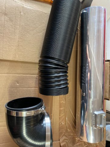
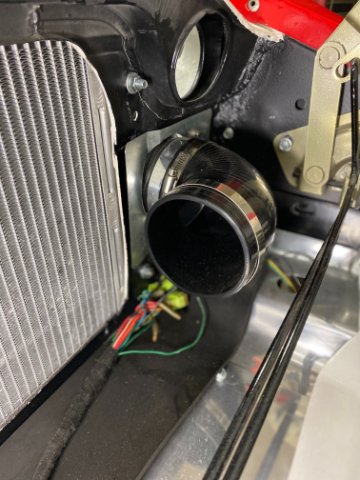
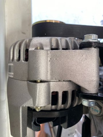
Engine Compartment Modifications- I forgot to post the Alternator that I utilized-NAPA #272-4717 104 AMP Alternator( cost $130). I originally tried to install a 140AMP GM one but it was way too large to fit in the bottom driver side of the motor. I think 104 AMP is sufficient unless I install an Electric Power Steering Unit. The NAPA Alternator has a Lifetime Warranty and 104 AMP is widely available. AIr Intake- My Crate LS3 6.2 Liter motor did not come with a Air Intake Setup so I had to fab one. Spectre Performance had a 4" Stainless Tube ($75), 36" 0fn 4" Flex Tubing($32)and 4" Right Angle Rubber Elbows(($24) for basis of my system. I didn't want my Air Inlet to breathe Hot Engine Compartment Air so I fab the system to get Cold Air from just behind the grille. Had to enlarge the hole in the Core Support to accomplish this. Also, had to "Tap " the Wheel Housing to get about 3/4" clearance for the Duct Hose. Used Shears to Trim the Sheet Metal Plate for the Duct Hose. Inside view of the Duct Opening Using Band Saw to cut 4" Stainless Straight Tube.. Trial Fitting of the Flexible Duct Tubing. I created a Steel Metal Duct Plate on the Core Support to hold Duct Hose and Air Filter. Pic of Additional Right Angle Elbow on outside of Core Support to mount Air Filter. I have not decided on which Air Filter to use yet. Inside view of Air Inlet System Next-Holley Terminator X System installation
-
Heavy Duty frame rails and connectors
toolman replied to toolman's topic in Gen III & IV Chevy V8Z Tech Board
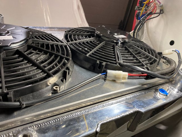
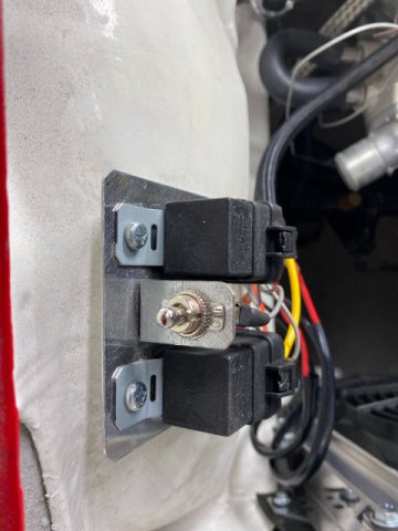
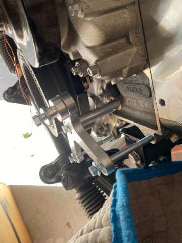
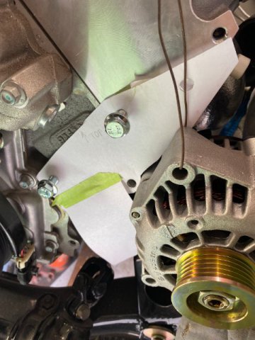
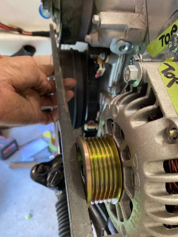
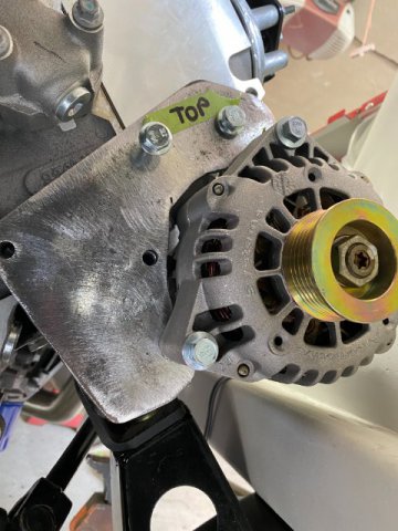
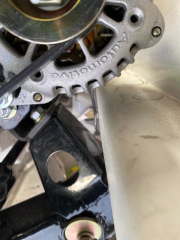
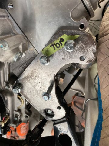
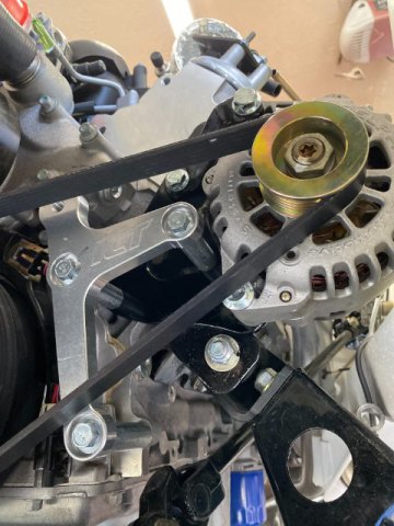
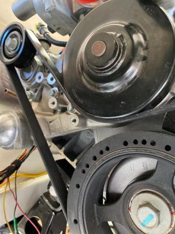
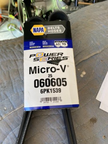
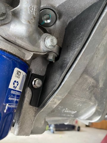
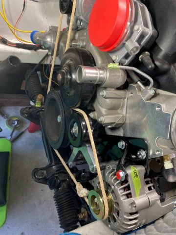
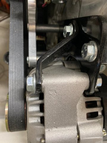
12vt Cooling Fans To go with the Champion Radiator, Two Spal 12vt. Electric Fans and Shroud were installed. The fans provide 1500 CFM of Air Flow but draw 27 maximum amperage. The Two Individual 30 Amp Relay are triggered by a 185 Degree Thermo Switch in the engine block. Spal Dual Fans with Shroud-Bottom View Dual 30 AMP Relays triggered a 185 Degree Thermo Swuitch. I also added an Emergency Bypass Switch to turn on the Relays in case of Switch Failure. Everything was mounted on the Right Side Wheel Well Housing. Alternator Mounting and Belt Arrangement- Originally ordered, a ICT Billet LS Motor Alternator Bracket from Amazon for $40. Unfortunately because my custom made Motor Mounts were located too far forward and the ICT Alternator Mount would not work. So I had to fabricate my own alternator bracket. ITC Billet Mount on my LS3 motor. As usual, I created a Paper Template for the Alternator Mount. Punching Alternator Mounting Holes in Template. Trial Fitting Paper Template Note-Alternator hanging in place with Tie Wire for positioning. Doing Drive Belt Pulley Alignment for Alternator to determine Spacer Size between bracket and block. Using rope to check Drive Belt Arrangement. Created the Mount out of 1/4 Plate Steel using the Template. Note- Plate is oversized so modifications can easily be made later. Checking Alternator Space Clearances Back of Alternator Determining Lower Mounting Bolt Length More Test Fitting Added an additional Upper Alternator to provide additional strength. This additional bracket creates a total of Three Solid Alternator Mounts. Finalizing the Fit Note-I left the ICT Billet Mount possibly use it to mount to a Idler Pulley in case I add Power Steering Pump. later. Used a 2017 Corvette Tensioner to handle Drive Belt Tension. The Final Version of the Alternator Mount Top view of Alternator Bracket Rrear View of Alternator A Dress Maker Cloth Tape Measure was wrapped around the pulleys to determine the Drive Belt Outside Dimension. Ii only took a couple of Drive Belts before I found the correct one. This one fit perfectly. Bell Housing Filler Pieces from AC Delco. Left AC Delco Bell Housing Filler Next-Engine Compartment Wiring
-
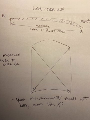
5 Star Rising, By your description of different gaps on your Core Support and your Hood Height problems, you might have Twisted Core Support. To verify that conclusion, you must make measurements of your front end. Place your car on a flat hard surface. Make your wheels in straight ahead direction. Take measurements in inches or millimeters. First, always measure from factory bolt holes vertically to the ground . Start at the 10mm bolt attached to the front inside of the Ringt and Left Headlight housings. Since this is the furthest bolt that is attached to the Front Core Support, any body damage will show up as significant differances in your Right and Left Ground Height measurements. If the damage is not too bad , it still can repaired but probably need a body shop to do the work. Please use measurements(in inches or millimeters) to describe your problems. This procedure will aid in determining how to fix your problem. Tool Man
-
5 Star Rising, If your main concern is the hood pushing back after you push it down, your problem is probably with the hood hinges and/or torsion rods. Note-if you have not removed your grille, you should as it will make easier to work on your hood and hinges But First, remove your hood and check for squareness. If your Hood is not within specs, the Hood is damaged and probably need to be replaced. Now, Remove the Hood Hinges and Torsion Bars. Replace the Hood on the car. Using shims( anything can be used) and attempt the "level" the hood as best as possible. This method will demonstrate if the hood can be made level with your car. If this can not be accomplished, the hood or car body is damaged. If the hood is level with the body, then the problem is with the hinges and/or torsion rods. Remove rods from hinges. Check both hinges and rods for damage and wear. Open and close hinges-full movement-measure if necessary. The rods are more difficult to inspect. Place them close together. Match the angles the rods on both rods. Being Spring Steel , the rod angles should very similar but spring tension is hard to measure unless you have a spring scale( like fish weight scale). If the hinges and/or torsion rods do not pass, replacement is necessary. If the hinge and rods pass, the next step is Hood Adustment. Replace Hinges but Rods off, this way you are check the hinges only. Adjust the hood(with no hood lock). With hood level and square, mark the hinges so you can replace the rods. If you can not adjust the hinges at this point, you may have slot the hinges mounting holes. You have to use the step by step method otherwise you never solve the problem. If this method does not solve your problem, you might have a damaged front end but that can be checked so keep posting. Tool Man
-
Heavy Duty frame rails and connectors
toolman replied to toolman's topic in Gen III & IV Chevy V8Z Tech Board
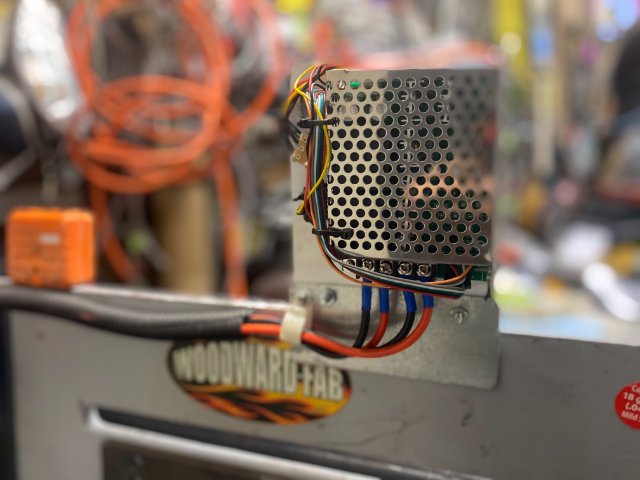
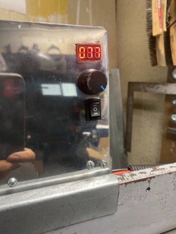
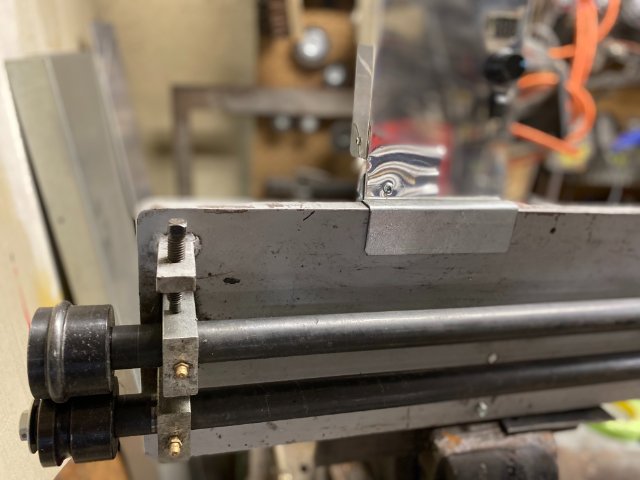
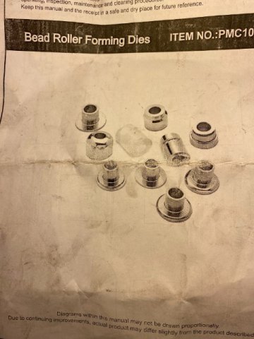
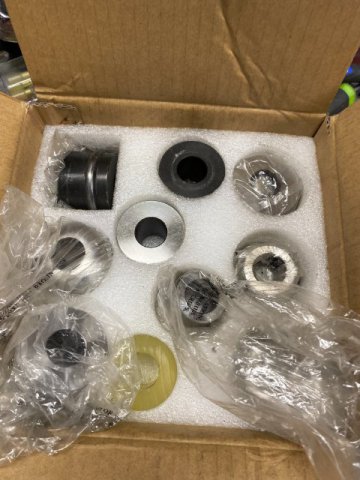
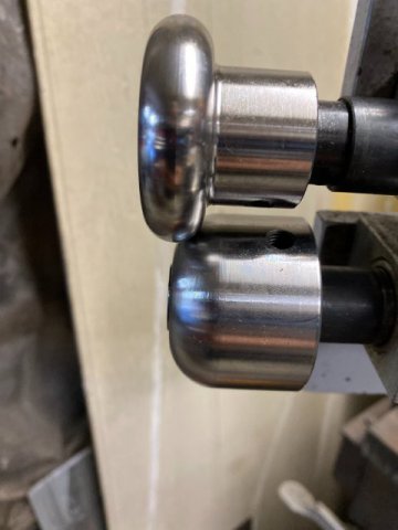
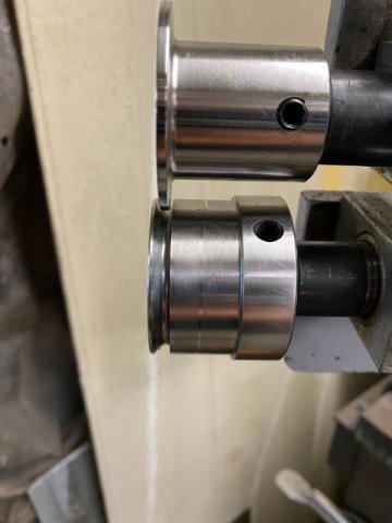
Bead Roller Modifications- After watching the video in my last post, you may have noticed that I made additional modifications to my Bead Roller to make using it even easier. I felt the Control Box was located too far right of the actual working area. So I removed the Power Convertor, Speed Controller and Forward/ Reverse Switch from the Control Box. They were relocated on the Bead Roller in self. These changes allowed me to control the Bead Roller Motor closer to the actual work area. Power Convertor moved to back of the Roller. The Speed Controller Panel was placed closer on the Roller for better visibility and speed knob and forward/reverse switch easier to operate. . Overall view of Bead Roller Video of Bead Roller including Foot Switch. https://www.youtube.com/shorts/UQrvfuUnM-s After these modifications, I also decided to add additional rollers so I would be able to do more sheet metal fabrication in the future. Amazon had a set of Bead Rollers for $150 and ordered it. Set looks like this. Wide Corner Bead Roller V Bend Roller V Flange Offset Rollers Offset Roller Results Narrow Round Bead Rollers Narrow Bead Roller Results Having fun playing with the Rollers but I got to get back to working on the Z. Next-Alternator Bracket Fabrication and Drive Belt Arrangement
-
Heavy Duty frame rails and connectors
toolman replied to toolman's topic in Gen III & IV Chevy V8Z Tech Board
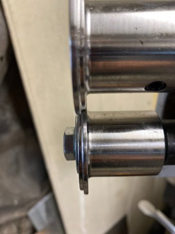
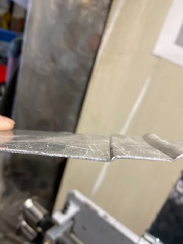
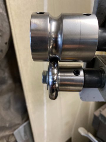
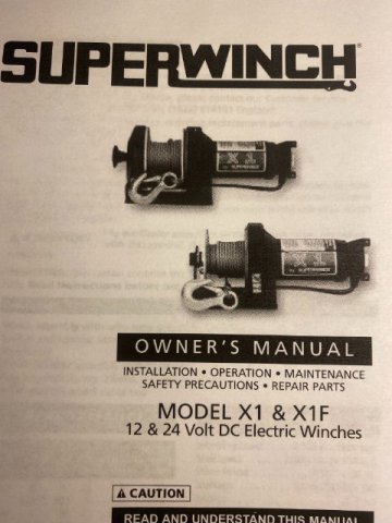
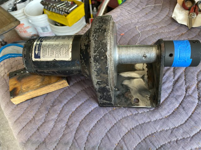
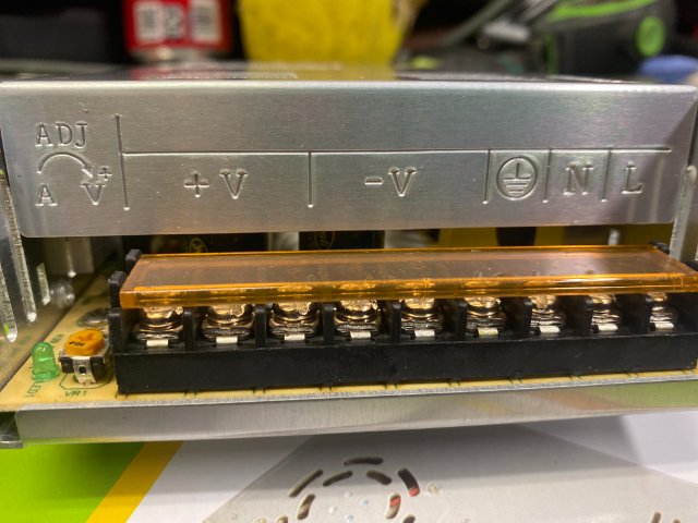
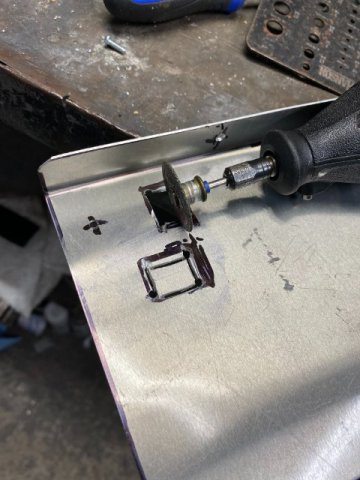
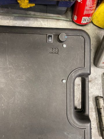
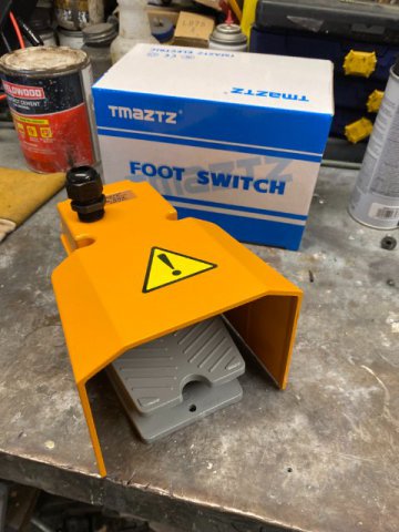
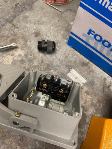
Motorizing my Bead Roller- I decided to put a Electric Motor on my Woodward Fabrication Bead Roller after I discovered that manual bead rolling requires another person to turn the crank. It was impossible to turn the crank and guide the sheet metal into the bead roller at the same time. I will attempt to motorize my bead roller for under $100 so anybodycan afford to build one too. The biggest expense would be the low speed but high torque motor. Fortunately, I found a old Super Winch which was about 20 years old off of a Honda ATV. It had a High Torque Low Speed Motor and it was Free. On You Tube, people have used all sorts of stuff to power their bead roller. Harbor Freight has ATV winches, 1/2 drills, electric pipe rethreaders,etc All of them could provide thenecessary power. Harbor Freight ATV winch can be gotten forabout $60-$70 for example. With my Super Winch, it was necessary to cut the cable spool off and shorten the spool about 2 1/2". Then the shaft was reduced to 3/4" to match one half of the Flex Coupling. The other half of the coupling was 1" to match the bead roller shaft. Amazon had a Flex Coupling 3/4 to 1 for $27. A flat spot was created on the motor shaft for the allen screw to prevent it from spinning. The winch body had to be shorten to compensate for the shortened shaft. Sorry i don't have pics because my friend who has a lathe at his house did the machine work there. Pic of Parts Breakdown of the Winch. Pic of Winch with Shortened Shaft and Body with Flex Joints attached. Pic of Outer Side of Motor Mounting Plate Note- reinforcing angles to strengthen plate against flexing. I ordered a 120AC to 12Vt DC 15amp Power Convertor from Amazon for $25. Closeup of Terminal Connections-AC in and DC voltage out. if your budget is tight, you can skip the Power Convertor and just use a Car Battery instead. A Variable Speed Controller,however is a necessity to control your work speed. Amazon provided the Variable Speed Controller for $24. The Controller had a Speed Control Knob, Forward and Reverse Switch and a Digital Display. The Display reads out in Percentage (1 to 100%) but looks neat anyway. Next was a Housing or a Box to put these electronic components to protect them against the elements. I found a right size plastic box to use and did a few mods to mount the components. Used a Hot Knife and Dremel to cut Square Holes for the Display and Power Switch. Box finished with Power Supply and Speed Controller Installed. At this time, I decided to add a Momentary Foot Switch in between the House Plug and the Power Supply. This switch would cut power off before entering a corner or stopping to change direction. I got it from Surplus Center for $16. I wired it so the switch could used for other motor devises like drill presses, bench grinders etc. Anthing that you might need your two hands to control the work piece. Closeup of inside the Momentary Switch Box This unit was Industrially quality and made of cast steel not molded plastic. Beads Roller Test Run- https://youtu.be/-nWKkfpzleI Next-More Bead Roller Modifications
-
Heavy Duty frame rails and connectors
toolman replied to toolman's topic in Gen III & IV Chevy V8Z Tech Board
Exposed, I have several Woodward Fabrication Tools-Manual Tubing Bender, Tubing Notcher, Shrinker/Stretcher, Hand Shear, Dimple Die set and assorted small tools. Their tools have better quality than Harbor Freight and are good for home craftsman. Practiced on some Aluminum with the Dimple Die Set. I hope to use the set on my Z maybe in the engine compartment or interior. Toolman
-
5 star raising, The best way to solve your problem is to post pics of your hood -pics of hood rear gap, left and right hood side gap, hood front edge compared to both L and R headlight covers and hood height (frnt ,sides and back). Leave the hood catch off till you fix hood alignment first. Always do one correction at a time then analysis the results. Take the pics, it will make it easier to solve your problem. Toolman
-
Heavy Duty frame rails and connectors
toolman replied to toolman's topic in Gen III & IV Chevy V8Z Tech Board
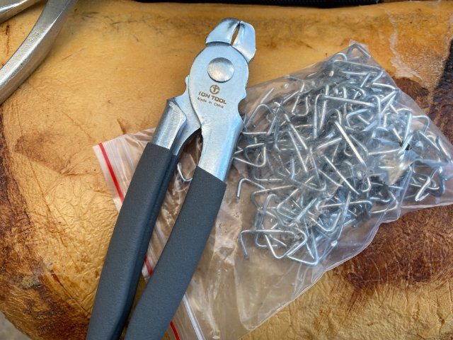
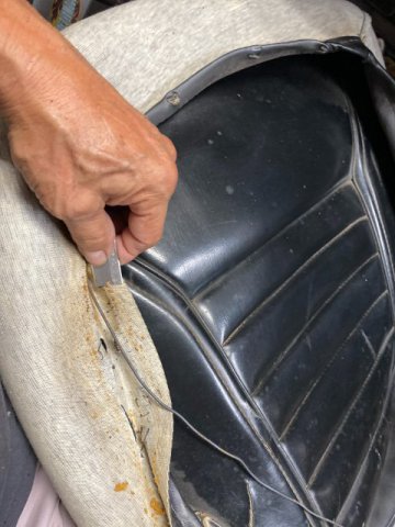
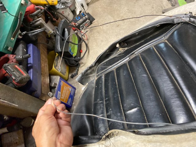
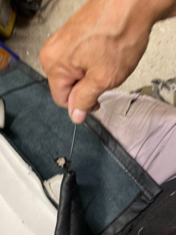
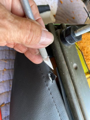
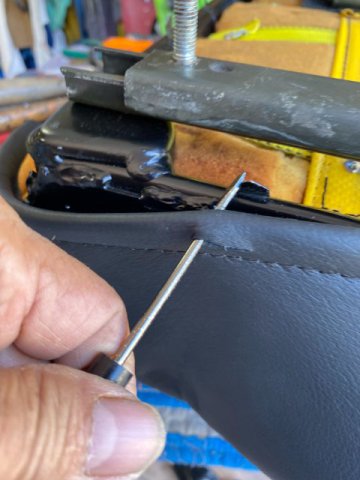
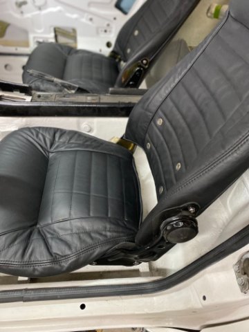
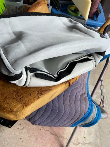
The Global Supply problems delayed delivery of my parts for modifying of my Bead Roller so I will go to LEATHER SEAT COVER REPLACEMENT- I ordered Two Leather Seat Covers from Interior Innovations for my car. Cost was about $700 including freight. Be aware- Once you ordered from this company and received your Order Confirmation, do not expect to hear from them until you received your seat covers. I tried to contact them by email and phone-no replies and no tracking number. But I received the covers after about one months time. On the upside, the Leather Seat Covers looked Good and Well Made but their Customer Service Suck! When I left off, the seats were without seat covers, the webbing was repaired and frame/seat back painted. a Hog Ring Pliers and some Hog Rings Clips. Before starting, you have to decide if you want to save the original Steel Wire located in the Rolled over Edges of both seat and back covers. I feel that the Steel Wire provides additional strength when stretching the seat covers on. The Replacement Covers have a small nylon rope instead. Using a razor to remove to remove wire from covers. Wire out of cover Tying Nylon String to the Steel Wire Initially you push the wire inward as you pull on the string with the other hand. If you encounter difficulty in pulling the wire through, attached the nylon string to a stationery object(like a vise) and slowly pull the wire through while keeping the seam straight as possible to prevents kinks. With the seat cover and foam facing the ground, insert 3 Nylon Ties into the Seat Flap. Tape both ends together temporarily. make the Ties wrap around the Steel Wire in the Flap. Place Foam Cushion over the cover. Then "Fish Out" the Ties out. As you found out, fishing the ties out was much easier because they were taped together. Place the Lower Seat Frame on the Cushion. Remove tape and tighten the Ties until the Flap contacts the Steel Wire. Use the Hog Ring Plier inside the cushion opening to install 3 Hog Rings to hold both the Flap Wire and Frame Steel Wire. Ties can cut off at this point. If necessary, additional foam can be added the top of the Bottom cushion. Place the Lower Seat Cover over the Cushion Foam. Work the foam under the cover be make fit properly. With a Cushion facing downward, the cover now needs to stretched over the seat frame. You start at the Center of the Front of the Bottom seat first then work equally down both sides to the Back. Cut a small slit in the Doubled UP Edge of the cover. Stretch the over the Pointed Tabs (making sure the tabs are grabbing the steel wire). A Wide Nose pliers or Vise Grip will make stretching easier. Do not bend the tabs completely over yet. If you having difficulty stretching the cover over the pointed tabs, a small screwdriver can be used as a pry bar to stretch the cover over the pointed tabs to secure it. Continue installing until you get to the bottom. Then, you pull up the Back Flap and fasten it down. Check the Top Side for any Low or High Spots. You may have to stick your hand under the seat cover and move the foam around. If you have vinyl Seat Covers, a Hot Air Gun might help removing wrinkles.. When the Seat Cover seems tight enough, you can now tap down all of the Pointed Tabs to add the Final Tightness. Seat Back Cover_ The same installation procedure is used on the Seat Back Cover. Replace the Steel Wire in the Top Flap and around the Bottom of the cover before you start. To Start, Turn the Back Cover "inside out" until the Top Flap is exposed. The top of the cover should resemble a cone shape. Install 3 Plastic Ties in the Top Flap of the cover. Place the cone portion of the cover cover over the top of the seat back. Slowly push and pull the cover down the seat. Add foam before sliding the cover that area. Stretch the cover over the Pointed Tabs till the right tightness is obtained. After the Front Side of the cover is good then pull and stretch the Back side of the cover down. After it is tight, then you can tap down the Pointed Tabs on the Bottom and call it Good. When installing the Seat Brackets, make sure to replace the Cleat Plastic Seat Cover Protectors. They will protect the covers from unnecessary wear. I replaced some them with copies made from 1/8" Rubber Sheets.. The pics of my Finished Leather Seats- I hope this post was not too long but tried to give helpful information. Next- Bead Roller Motorized Modifications
-
Heavy Duty frame rails and connectors
toolman replied to toolman's topic in Gen III & IV Chevy V8Z Tech Board
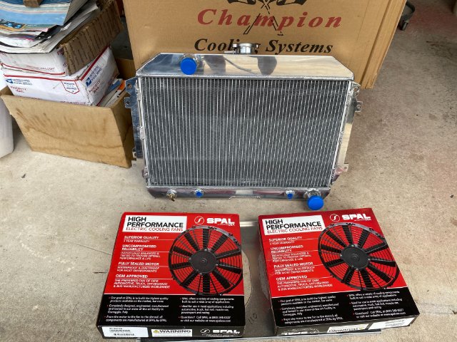
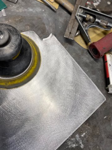
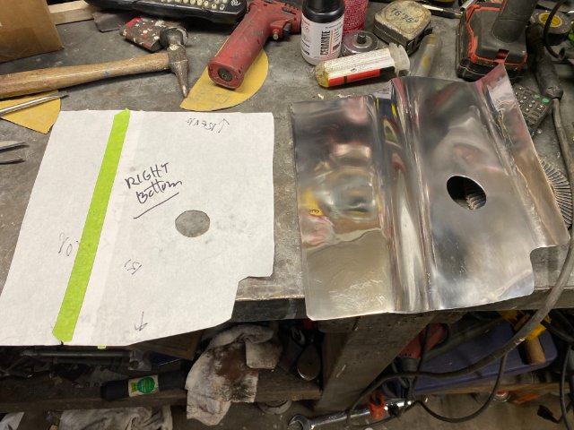
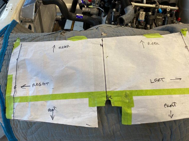
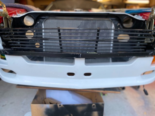
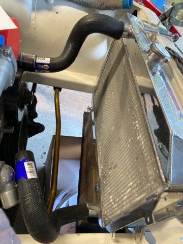
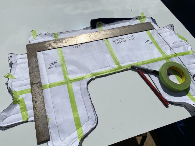
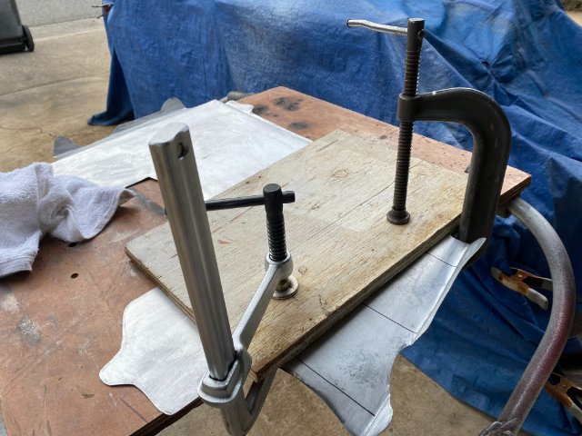
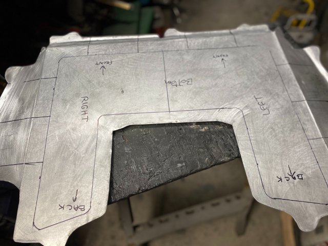
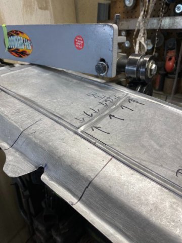
Cooling System- A lot of time was spent looking a radiator for my LS 240z. The biggest problem was the 28" space between the Front Core Support. Most available LS radiators were about 30" wide. But I found 67-69 V8 Camaro had narrow width of 27". So I called Champion Radiator for Pricing and Availablity. He said because of the Pandemic affecting the supply channels, none was available and would not be for couple of months. But fortunately, he asked me what kind of radiator that I was looking for. I told him 71 Datsun 240Z with LS swap. Then he said they have Datsun Z radiator for Chevy V8 swaps in stock. The Radiator have 3 cores and can handle 500 HP. Its dimensions are 27.25" with brackets and core was 2.75 thick, 1.5" drivers side inlet and 1.5" passenger side outlet. The Radiator cost with two 11" Spal electric fans and shroud was $389. Shipping by US POSTALwas $130. Totaling out at $519. The Champion Radiator arrived less than a week later. it was a Bolt On fit and even came with a 13lb radiator cap. The Test Fit showed the Radiator Cap cleared the Hood Bulge by !" clearance. The Upper Radiator Tank was built with Forward Downward Angle which aided in the clearance. Looking at the Grill Area, I decided to improve the Air Flow to the Radiator. This would be accomplished by blocking off the area between the Core Support and the Front Air Dam. Using Three Pieces of .025 Aluminum Sheet Metal to create the Blocking Section. First thing to do was to remove the White Paint on the Aluminum Sheet. This was done by sanding with an Orbital Sander with 80 grit sand paper. A Paper Template were made to create the Three Blocking Sections. The Round Holes were cut into the Two Outer Plates for the Grill Lower Mounting Brackets. Test fitting of the Blocking Sections. The Right Section was attached to the Core Support using Metric Nutserts. The Paper Template of the Center Section. The Front Slot provided clearance for the Grill Bracket. The Front View of the Grill and Blocking Sections under the the Bumper. Test Fitting of the Champion Radiuator. Napa Radiator Hose #8330-Upper and #708 -Lower had to shortened to properly fit. At this point, I decided to attempt to construct the Front Engine Pan out Aluminum Sheet. A Polished Aluminum Engine Pan would look Sharp in the engine compartment. The Original Front Metal Engine Pan Making Paper Template of Engine Pan. C Clamps were used the hold the sections from moving when polishing. After Sanding, the Guide Lines for the Bead Roller were drawn. using the Woodward Fab Bead Roller, the Reinforcing Beads were made to stiffen the pan. After making a few beads, I discovered how difficult the beading process was to do by ones self. Trying to hold the metal straight and stretching over to turn the crank was next to impossible!! So decided to look into Motorizing the Bead roller. These On-Line motor conversion run about $400 to $800. I going to see if it is possible to do it for under $100. Wish me Luck!!
-
Heavy Duty frame rails and connectors
toolman replied to toolman's topic in Gen III & IV Chevy V8Z Tech Board
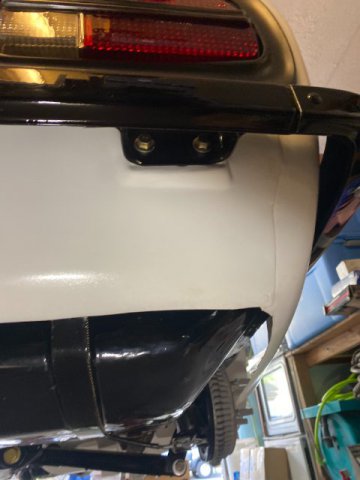
calZ, In my case. There is no room to install a muffler on the Right Rear of the car. See pics below- Looking for Right Wheel Housing toward rear. Looking Forward from Right Tail Light. I mounted a Holley Electric Fuel Pump in the a Custom Fuel Tank Sump. Installed two 3/8 Nickel Copper Fuel Line and In-Line Fuel Filters running through the Trans Tunnel.
-
Heavy Duty frame rails and connectors
toolman replied to toolman's topic in Gen III & IV Chevy V8Z Tech Board
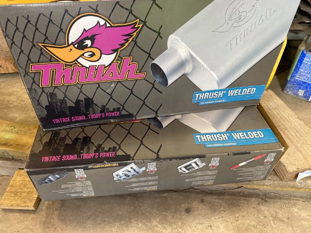
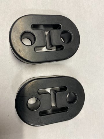
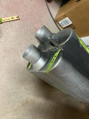
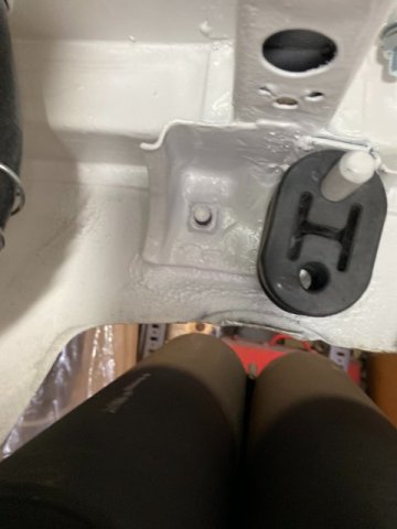
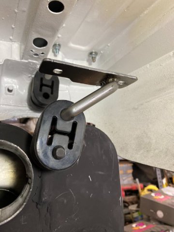
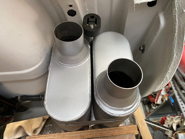
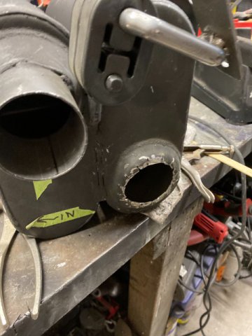
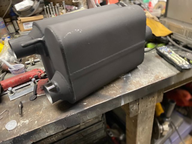
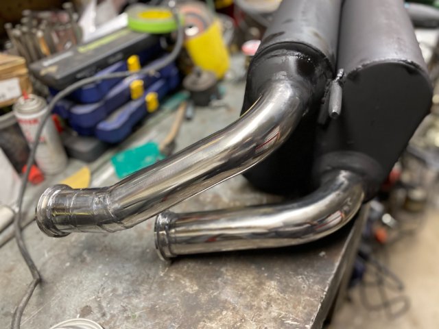
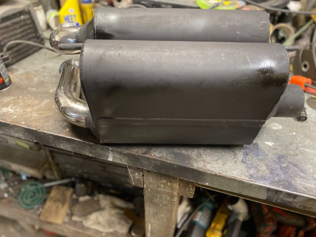
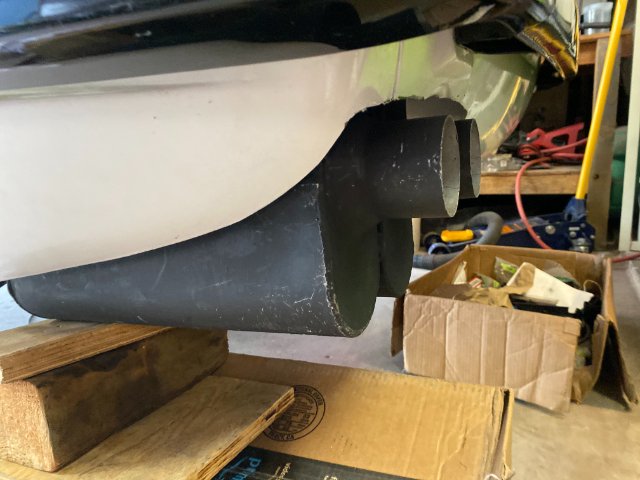
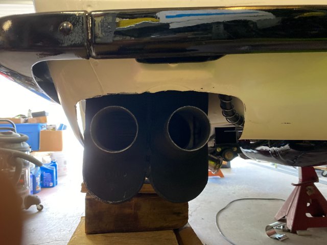
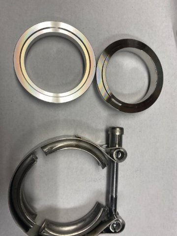
Mufflers and more Exhaust Work- I picked Thrush Turbo Muffler which consists of a Aluminiuzed Coated Steel Metal Body because of its small size and light weight. But after Trial Fitting, it was little too long. The original 240Z muffler space was made for only one muffler not two. Returned those mufflers and order Thrush Welded Turbo version which were 1" narrower and 1" shorter. This installation was go down to a matter of inches of clearance. The only disadvantage of these mufflers was there were constructed of 16 gauge metal so they were heavy. They were Duct Taped together(to stimulate being welded together) and Test Fitted in. It was a Tight Fit. Had to cut about 1" of the Lower Bottom Edge of Quarter Panel to gain Side Clearance. Supporting the Mufflers was another problem because of the tight space. So I decided to construct a Single Hanging Muffler brackets. So the mufflers were going to be welded together and supported by 1" steel rods located on centerline of both mufflers. Also, because of the heavy weight of the mufflers , Two Rubber Mounts (or a total of four mounts) would be used. Mufflers were welded together with 1/4" piece of steel to provide a mount for the 1/2'" steel rod hangers. Steel Hangers welded on. The Rear Muffler 1/2" Rod Hanger was welded to the bottom of the Rear Bumper Mounting Bracket. Note- There are two Rubber Mounts on the rod. This would be the Stationary Mount. So when installing the Mufflers, you just insert the Upper Muffler 1/2" rod into the Rubber Mounts and push the Mufflers 0n. Then the Wheel Housing Mount can be installed. This Wheel Housing Mount is attached to Two 5/16" Bolts welded to a strip of 1/8" plate on the Hatch Floor. Closeup pic of Wheel Housing Mount with Hatch Floor mount. Mufflers installed. The Outer Muffler Inlet Pipe still had to be modified to gain Tire Clearance. The Inlet Pipe had to shortened as much as possible. Inlet Pipe shortened. Mufflers with Connecting Exhaust Pipes installed. Note-V-Band Clamps. Side View of Mufflers Mufflers were painted with HighTemperature Black Paint before installation. Side View of Mufflers Rear View of Mufflers
-
Heavy Duty frame rails and connectors
toolman replied to toolman's topic in Gen III & IV Chevy V8Z Tech Board
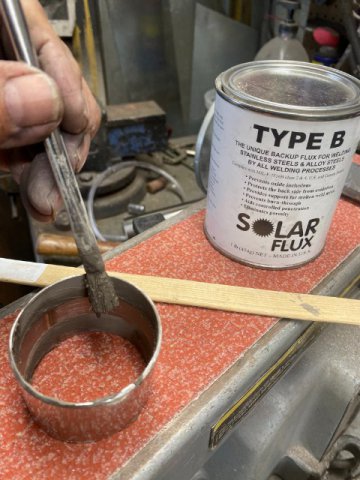
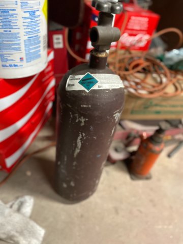
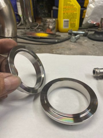
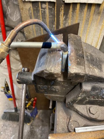
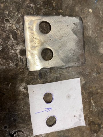
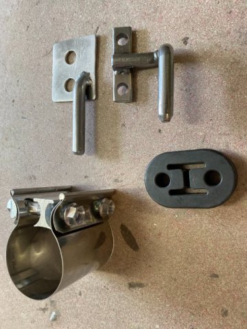
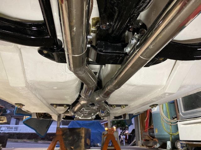
More Exhaust Work- Pie Cutting- First, Creating a Paper Template for Reference Points o the exhaust pipe. This Diagram is for a 2 1/4" Exhaust pipe( just substitute your pipe size). First, use your pipe size times Pie=3.14. The result is the Pipe Circumference. In this case, the result is about 7.06 inches. So cut your Template out Thin Cardboard or HD Paper to resemble a ruler. Divide the Circumference by 2 to get the Half Way Point which is about 3..53 inches. Wrap the Template about the pipe and the ends should meet together. Now , Draw a Straight Line down your pipe with Marker Pen. Mark this Line #1. Use a Right Angle Protractor if necessary. Wrap the Template around the pipe and transfer the Half Way Point to the pipe. Draw a Straight Line Down the length of the pipe. Mark this Line #2. Put your pipe into the Band Saw with Line #1 facing Straight up. Adjust the Band saw to Desired Angle (usually 7 1/2, 15 or 30 Degrees). Make the Cut. Remember this First Cut will have a Straight Edge on One Side. Now, Rotate the Pipe to Line#2 (about 180 Degrees). Push the pipe inward which will determine the tightness of the Radius. This will be the Thinnest section of your Pie Cut( so keep it al least 1/4 inch wide or bigger). Do not forget to bevel both edges and sand the edges for the welding. Also paint the inside of the area to be welded with Solar Flux with an acid brush. Tig Welding is Super expensive here. My 20 -Argon Tank refill cost me $325. If that is not Outrageous, I don 't what is!!! $$$$$$$$$$$$$$$$ My X-Pipe cost about $40 from Amazon. A Jack Stand was used to support the x-Pipe while setting up. X-Pipe Welded Up V-Band Clamps were utilized to allow easy maintenance later(trans removal, driveshaft,differential, etc) Male/Female Style V-Clamps Close Up View These V-0Clamps have Male and Female Connecting Edges which creates better alignment and sealing. Exhaust Pipe Hangers Amazon provided the Rubber Exhaust Hangers for $9 a pair. These mounts were used because of their small size and strengthen. The Hangers themselves were constructed with 1/2" Mild Steel Round Rods. The Rubber Mounts normally use 7/16" Rods but since my mufflers were going to be Heavy so the 1/2" Thicker Rods were used. !/2" Rods being bend with a Torch. Making the Pipe Hanger mounting plates These Upper Plates attach to the Differential Strap bolt holes. The Exhaust Pipe of the Pipe Hangers were fabricated from 2 1/4" Stainless Exhaust Clamp Bands(from Amazon for $18. These Clamps allow easy removal and installation. Also, they can slide down the pipe to relocate the hanger if necessary. Rear View of Exhaust Hangers attached to Pipe Clamps(look just below Differential Cover) Bottom View of Exhaust Clamps attached to Pipe Clamps. Right Side View Left Side Rocker Panel View-I tried to locate Exhaust Pipes high off the ground as possible. Right Side Rocker Panel View Next-Mufflers and More Exhaust Work
-
Heavy Duty frame rails and connectors
toolman replied to toolman's topic in Gen III & IV Chevy V8Z Tech Board
My Post will be delayed because my Residence on the Eastern Portion of the Island is experiencing a Local Emergency-A 24 inch Water Main Break. It has been Two Days since we have had running water!! I have a go out Three Times a day to pickup 3 Galloins of Water from a Water Tanker. This Water is not for Drinking but just for Flushing the Toilets!! Tthe Water Company said the Water Main should be fixed Today but we since Don't Have Water Pressure yet. The only shower that I take is Wiping myself with Water from a bottle of water onto a Wash Cloth!!!. Ughhh. -
Heavy Duty frame rails and connectors
toolman replied to toolman's topic in Gen III & IV Chevy V8Z Tech Board
. -
Heavy Duty frame rails and connectors
toolman replied to toolman's topic in Gen III & IV Chevy V8Z Tech Board
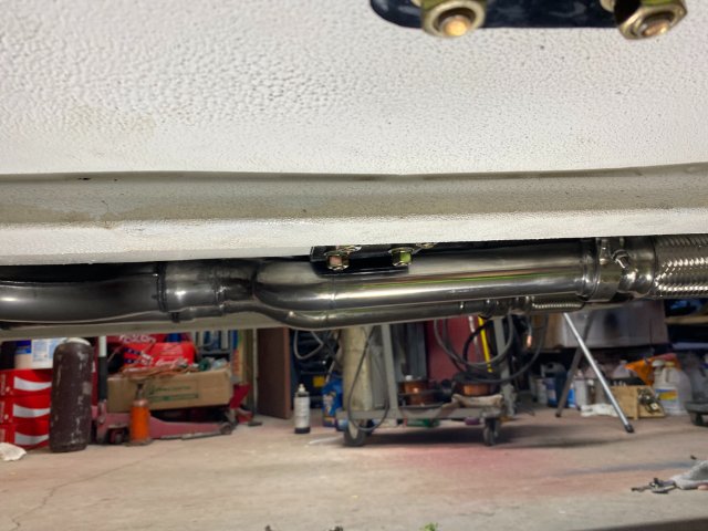
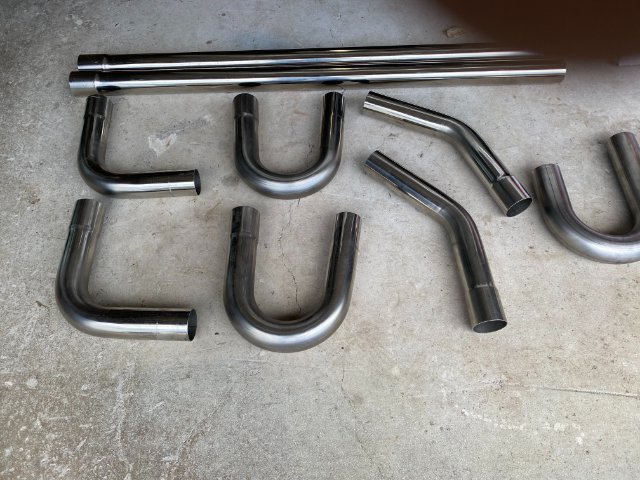
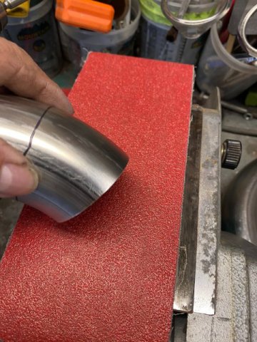
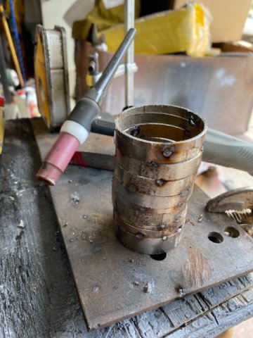
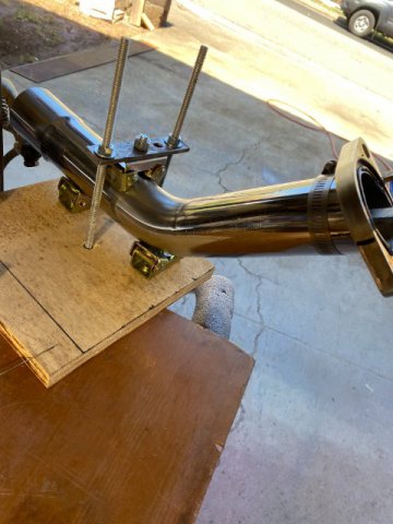
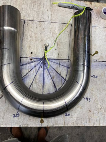
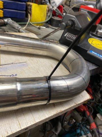
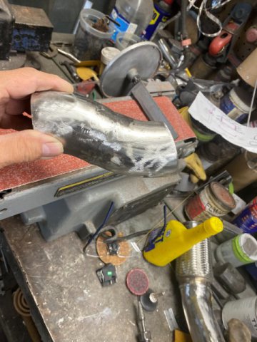
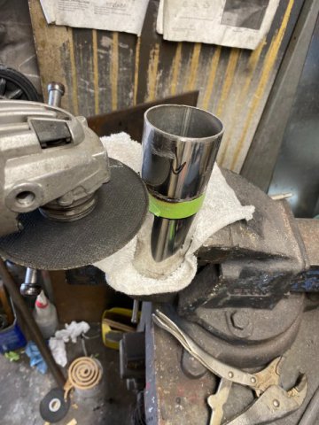
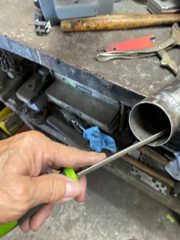
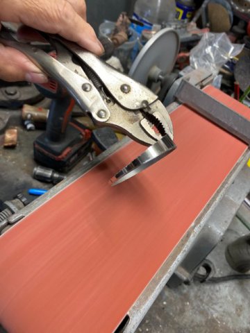
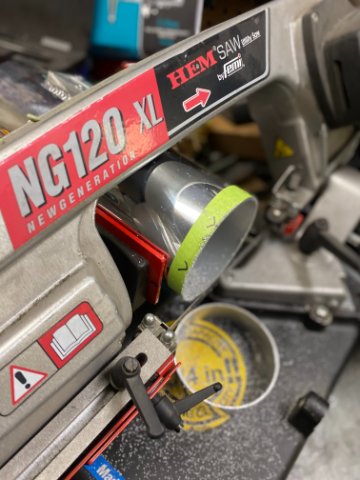
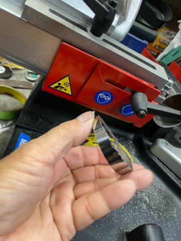
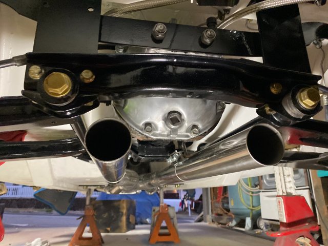
Exhaust Pipe Construction I started off with Super Fast Racing 2 1/4" Stainless Steel DIY Custom Exhaust Pipe Kit from Amazon. It was about $149. The kit consists of Two 45 degree, Two 45 degree, Two 90 degree bends and Two 48" straight sections of T304 Stainless Pipe. I used a Electric Band Saw that can cut up to 4 3/4" .but you can use a !4" Chop Saw, a Sawzalll or even a 4 1/2 Right Angle Grinder with !/32" cutting disc. A Band Saw does make the job easier. A Craftsman 2/3 HP Belt Sander was utilized to straighten cut pipe edges. A 4' x 36" x 36 grit Ceramic Belt provided fast sanding. A Astro Pneumatic Small Air Belt Sander with 80 girt belt was useful in sanding tight areas, Since this project using a Tig Welder, there was going to be a Very Steep Learning Cruve involved. So I practiced, practiced and practiced. Welding Thin Wall Stainless was like being thrown in the Deep Side of the Pool while learning how to swim! But I managed to get a hang of it but my Tig Welds were not anything to brag about. Practicing Butt Joint Welding When Tig Welding, Clearness is vital. So you wipe down the area to be welded with Acetone to remove any contaminates ( from even brand new parts). Then, you should bevel both edges of your Butt Joints and sand the weld area. At the same time get the Butt Joints as Tight as Possible. Here is a Welding Tip: Instead of Purging with Argon Gas the inside of the pipe, use Solar Flux type B. It comes in a Pint can and cost about $49 on Amazon. It is a dry powder that you mix with Alcohol to create a mud like paste. You brush it on the inside of the pipe under the area to be welded. When it dries, the paste will prevent "sugaring" which is oxygen contamination of bottom side of the weld. Sugaring will create a tiny facture which can crack later especially something subject to constant vibration. Another benefit is Argon Purging is very Expensive so wasting it is foolish. Solar Flux, however, can not be used upside of a turbo because its residue might get suck in and damage the turbo blades. I also constructed a Tig Welding Jig to hold round exhaust pipe when welding. The round pipe can be easily rotated when tig welding the butt joints. To cut the U-Bends, I created a cutting board to mark the pipe for cutting. Using the string and a marker pen to mark off angles. Zip Ties on the pipe helps making lines around the pipes. After Cutting the U Bend, you will notice that pipe sections are not perfectly round( more "egg shape". This is because these so called Mandrel Bends are not True Mandrel Bends. Just Cheap Versions. However, True Mandrel Bends are available but cost a lot more. .Passenger side Front Pipe Driver Side Front Pipe Two Flex Pipe Sections were used to absorb engine vibration to exhaust pipes. Using 3M Masking tape to hold sections whenf test fitting. Creating "S"Bend pipe Cutting with a 4 1/2 Right Angle Grinder. Use the Thinner 1/32" cutoff wheel makes cutting easier. Removing the sharp edges after cutting eliminate potential stress points. Making Pie Cuts Next-More Exhaust Work
-
Heavy Duty frame rails and connectors
toolman replied to toolman's topic in Gen III & IV Chevy V8Z Tech Board
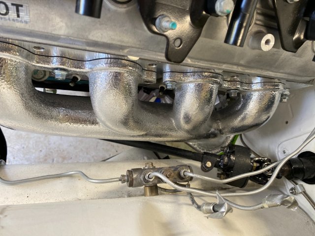
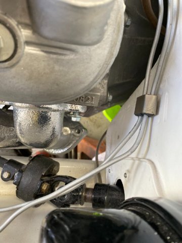
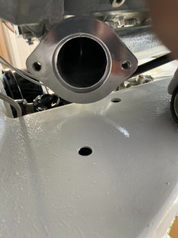
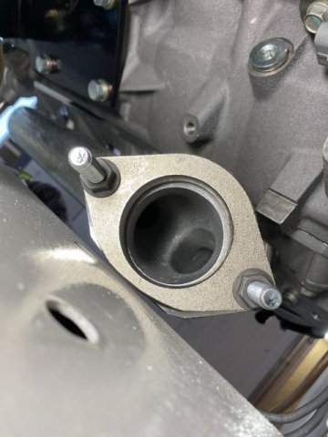
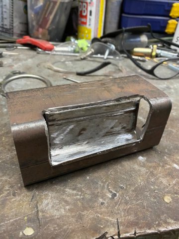
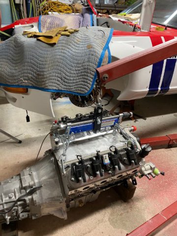
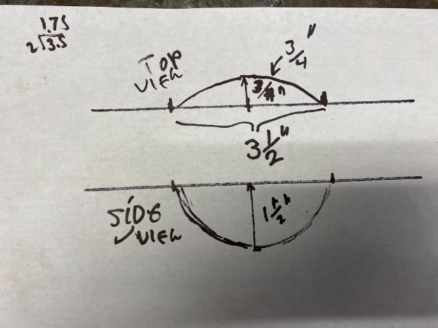
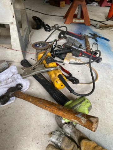
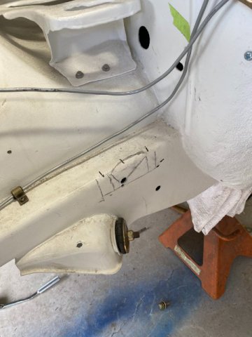
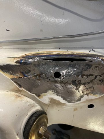
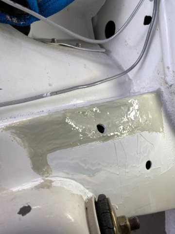
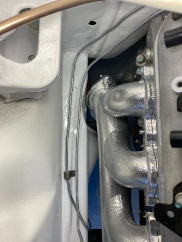
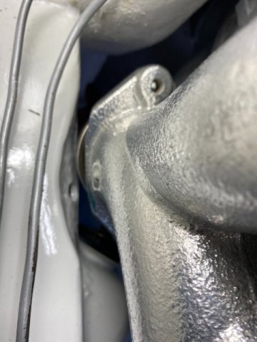
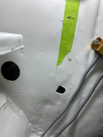
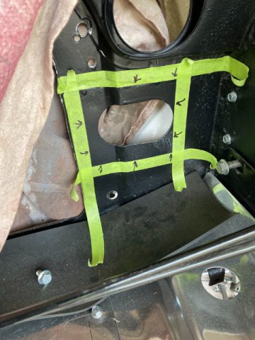
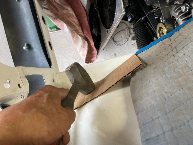
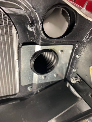
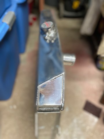
New Exhaust System- After installing the Holley Flow Tech LS exhaust manifolds on my car, I discovered there was a Clearance Problem. The Driver Side -No Problems Steering Shaft Firewall Frame Rail However, the Passenger side Exhaust Manifold was too close to the Frame Rail. The Passenger Side was touching the Frame Rail so I tried to cut off about 3/8" off the bottom manifold ourside edge. But ,it was still too close. I considered shifting the motor to the left but that side didn't have the extra space. So the only alternative was to "Notch" the Frame Rail. This is one the possible Notch design. This model was made using the same Frame Rail material. But no matter what, Notching would require the motor and transmission removal again! This would be the Sixth Time the Motor/Trans had to be removed. Nobody said engine swaps were Easy, right? Out Again This is the my Drawing of the Frame Notch modification. Here is a pic of the Tools necessary for this job. The Passenger Frame "Marked Out" in preparation of the modification. A 4 1/2 Right Angle Grinder with Cut Off Wheel was used to slice the Top Edge of the Frame Rail. Then a Oxygen Acetylene Torch heated the Notch area "Cherry Red". Then a 5 pound Sledge Hammer pounded the area. to create a "Rounded Spot" The Upper Frame Rail were cut to match the cruve of the Notch. Then 3/16" gap was then welded with a Mig Welder with Two Welding Passes. The Notch and Weld was grinded and covered with EverCoat Polyurethane Seam Sealer. The area was then painted with Polyurethane White Paint. Note-those holes were previously drilled there for future rustproofing access. The rust proofing plugs will then be installed, Top View of Notch Closeup View The Brake Line was moved away from the Manifold at this time. The Vapor Line was also moved. Next- Exhaust Pipe Construction
-
Heavy Duty frame rails and connectors
toolman replied to toolman's topic in Gen III & IV Chevy V8Z Tech Board
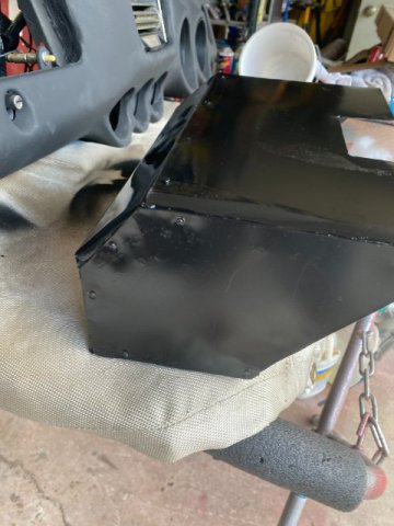
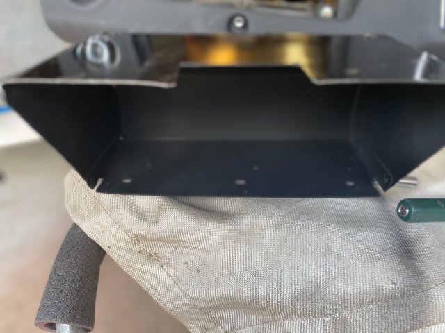
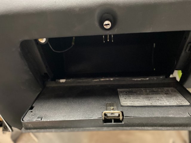
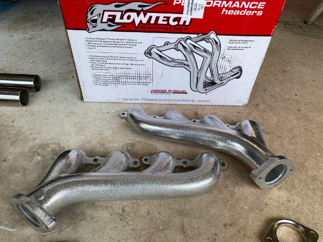
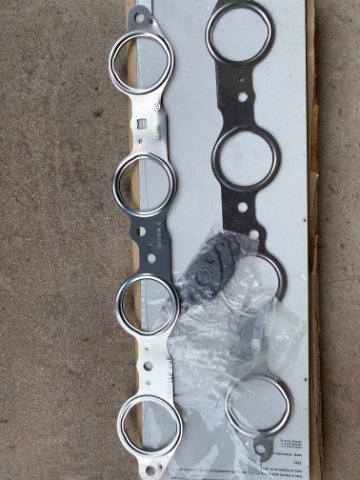
DonH, Thanks for feedback on the Leather Seat Covers. Good to know that Company makes Good Covers. Dash Board Installation- After receiving the SEM Textured Black Dash Board Paint, I repainted the Dash Board. But while installing the dashboard, I discovered that the my Aluminum Replacement Glove compartment had to be modified to fit. The Compartment Top had to be Notched to clear Dash board Ducts Hoses. Used the Brake to create the Notch for Glove Compartment. Cleco Pins were used to test fit the Notch on the Glove Compartment Box. The Notch installed on the Box. Interior of Box was painted with SEM Textured Black Paint. Pic of Finished Dash Board Installed. Giove Compartment Box completed. For those of you who missed the Dash Board Restoration- Go back to Feb 4, 2019. The Dash Board was in Eight Pieces after it fell off my work bench. Exhaust System Build- I decided to build my Exhaust System starting with Holley Flow Tech LS Cast Iron Exhaust Manifolds. They have 2 1/4" outlets and are Ceramic Coated. Cast manifolds will eliminate some of the Heat and Sound in the engine compartment. Ebay sells them for about $260. The Rest of the Exhaust System would be fabricated from this Universal 2 1/4" Stainless Steel DIY Kit from Ebay. It costs about $150. LS Exhaust Manifold Gasket Kit runs about $20 on Amazon Building an Exhaust System for a 240z without a Exhaust Tubing Bender and a Vehicle Hoist will not be easy. Especially making it out of Stainless Steel Tubing and the fact that I never Tig Welded before. Please be Patience with me!!
-
Heavy Duty frame rails and connectors
toolman replied to toolman's topic in Gen III & IV Chevy V8Z Tech Board
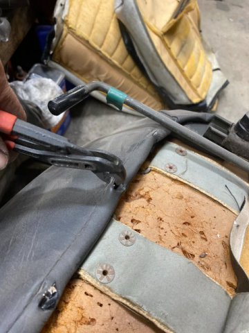
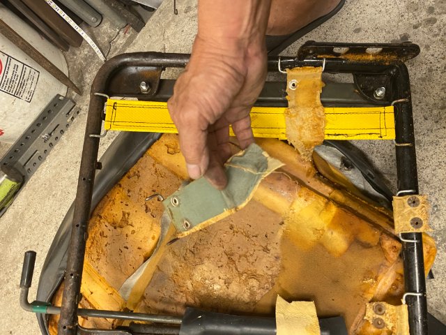
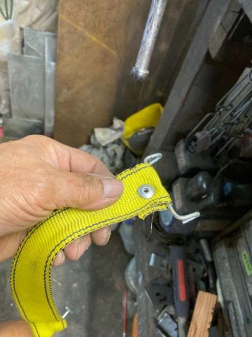
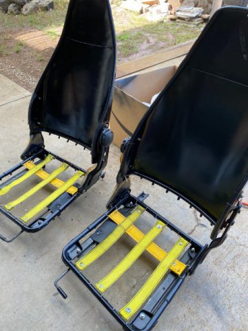
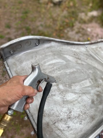
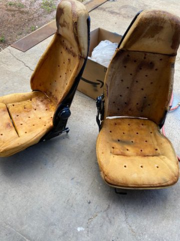
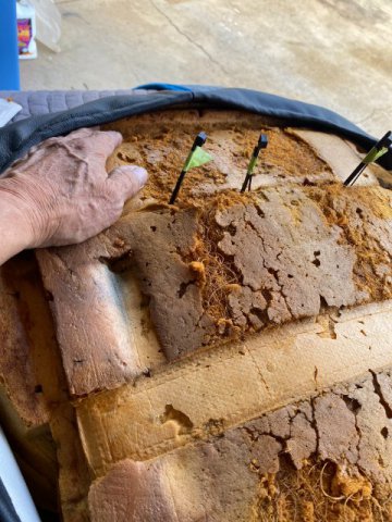
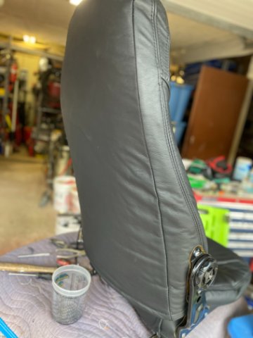
Sorry for the delay in posting but couple of unforeseen problems came up. I was planning to go over the installation of my Reconditioned Dash Board but could not find the SEM Products Textured Dash Board Spray Paint on the island. Since Federal Express and UPS won't ship Pressurized Containers, my Spray Paint would have to come by Boat. That trip would two to three weeks so I went to another item to restore. Front Bucket Seats Restore Both Left and Right Seats had lot of wear so probably would go Restoring them in Leather. First Step was to Disassembly to check the internal condition of the seats. Removing the seat coats just requires removal of the Hog Rings that hold the covers on. Sand Blasting Seat Frame and Back They put a Thin Clear Plastic Sheeting over the Seat Foam to make it easier to "slip" the new Seat Cover over the Foam. It can be replaced with any real Thin Plastic Sheeting(like the kind from Dry Cleaning Shops). Both Seats had Broken Seat Support Straps( located under the foam seat cushion). If you plan to repair the seats, you need to save the Metal Support Wires that hold the seat covers to the frame as they might not come with new seat covers. I used Webbed Belts from Ratcheting Cargo Straps to replace the Broken Straps. Loop the Cargo Straps around the Old Factory Strap Connectors . Hot Glue is used between the Folds to provide additional strength. A 1/4 Air Riveter is used to install the 1/4 rivet to secure the webbing tightly too. Solid Aluminum Rivets can be utilized. Close Up View of Repaired Strap Both Seat Frames were sandblasted and painted with Black Urethane Paint. Seat Cushion Straps installed. Seat Cushions installed awaiting Seat Covers. Pricing both Vinyl and Leather Seat Covers on Amazon and Ebay came out to $400+ for Vinyl and about $700 for Leather Seat Covers. I decided to wait and possibly look for Junk Yard or Craigslist for a Pair of fBucket Seats. Next-Exhaust System This should be interesting as It will be the First Time that I will Tig Weld and Weld Stainless Steel Exhaust. Wish me Luck!


.JPG.a7aa8071550d11c6d746c81a78b84e60.JPG)


.JPG.86ec74376c700192db938841f828250a.JPG)
.JPG.4e69c45153c2a68f2f1247183e68a661.JPG)
.JPG.f86668ee5fa104dca02a3592257fa1ac.JPG)


.JPG.8be49e2b83918485652c266272183a4a.JPG)


.JPG.4543cc27fd2c96e1886378730f4a41d4.JPG)


.JPG.8fd42940c991c6d9fe78446a37ee597e.JPG)