toolman
-
Posts
616 -
Joined
-
Last visited
-
Days Won
25
Content Type
Profiles
Forums
Blogs
Events
Gallery
Downloads
Store
Everything posted by toolman
-
Heavy Duty frame rails and connectors
toolman replied to toolman's topic in Gen III & IV Chevy V8Z Tech Board
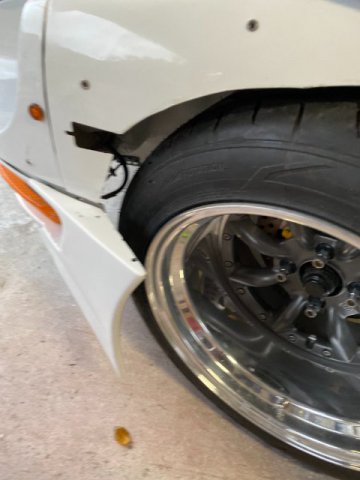
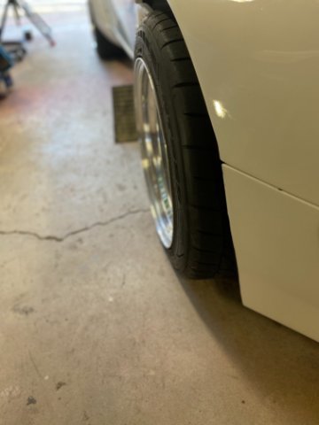
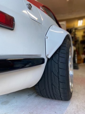
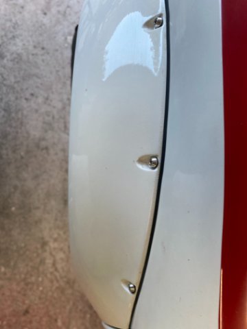
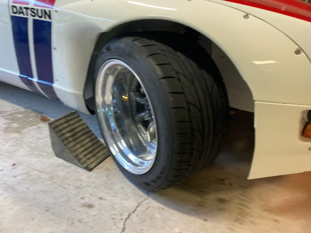
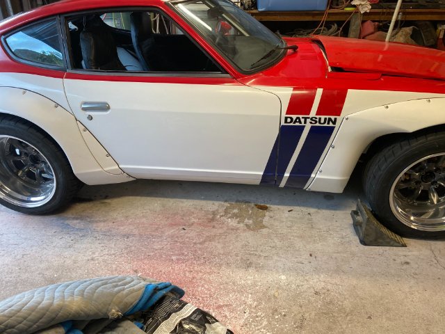
Walkerbk, Yes, I had to trim the back area of the Tocket Bunny Flare to provide tire clearance when turning. I tried to maintain at least 1/2" clearance between flare and tire during the full tire movement. I think this tire clearance also allows for body roll too. Toolman -
Heavy Duty frame rails and connectors
toolman replied to toolman's topic in Gen III & IV Chevy V8Z Tech Board
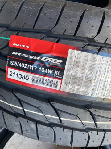
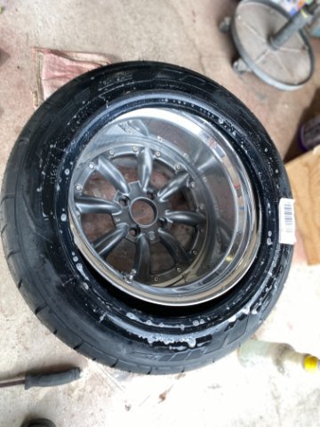
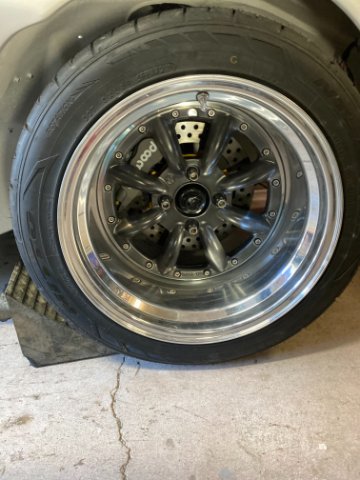
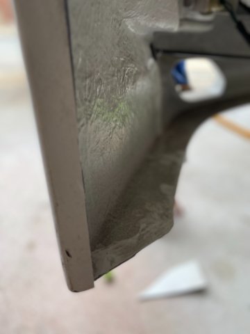
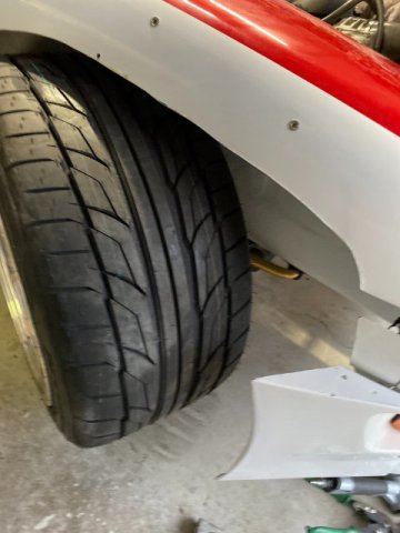
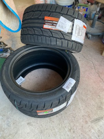
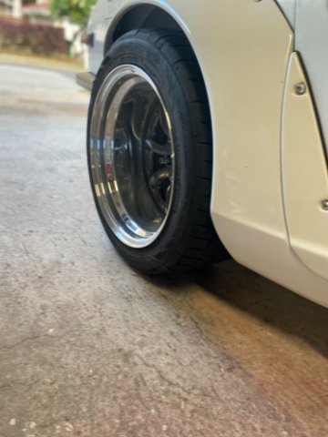
WHEELS AND TIRES- The Wheels that I selected were custom made by Love20Bee in Los Angeles. They specialize in custom wheels especially for JDM cars. I wanted Watanabe Insets with deep offset wheel barrels. The owner has several 240Z himself. The Front Tires are Nitto G2 285/40/17 with 11" Tread Width. The Rear Tires are 315/40/14 with Thread Width of 12" The Wheels are Custom Made with Watanabe Inserts(with Dark Grey Metallic Spokes) with 11" Wide barrel in the Front and 12" Barrels in the Rear. Checking for Leaks. Wheels and Tires Installed. Rear Wheel l Front Wheel Cutting Rocket Flares for Tire Clearance- The Greddy Rocket Bunny Flares had to be cut because of the Deep Wheel Offeset for Tire Clearance. Front Flares before Cutting. Note-Without cutting, Tires could not turn. Inside view of Front Flare before Cutting-clearance. About 3" had to removed for Clearance. Rear of Front Tire Clearance After Frontr Cutting View of Front Tire View of Front Tire View of Rear Tire Rear Tire Front View Rear View of Rear Tire Top View of Rear Flare Rear Tire Clearance with Muffler/Exhaust Pipes. Inside View of Tire Clearance. Full Right Turn Side View of Car Four Watanabe Wheels (Polished lips and Gun Metal Spoked Face---$4000.00 Love20BEE 2nd Day UPS Freight 240.00 Four Nitto G2 285 and 315/17 tires (Amazon) 860.00 __________ Total $5510.00
-
Heavy Duty frame rails and connectors
toolman replied to toolman's topic in Gen III & IV Chevy V8Z Tech Board
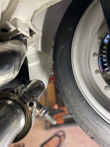
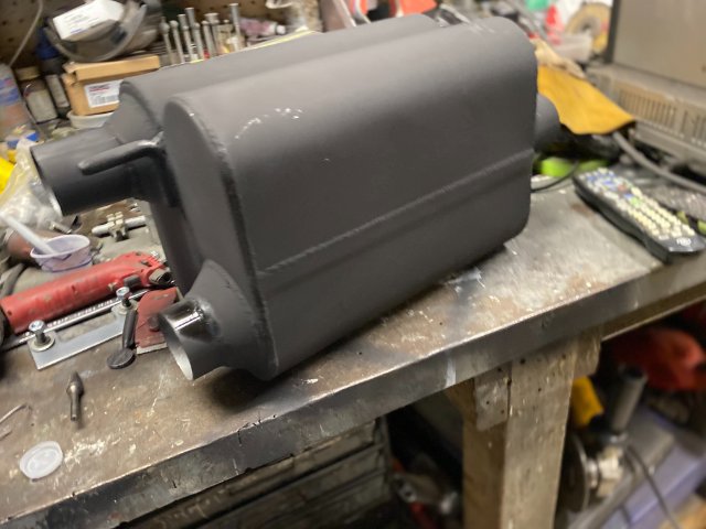
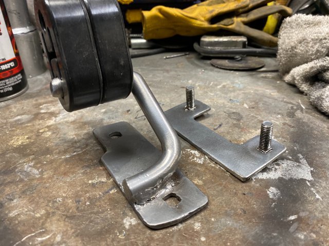
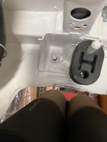
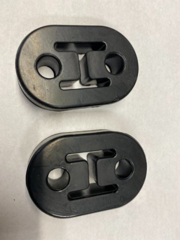
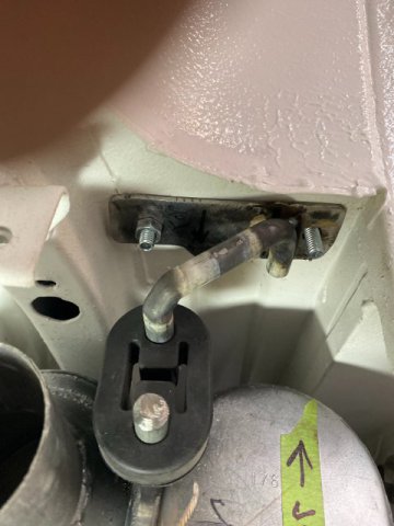
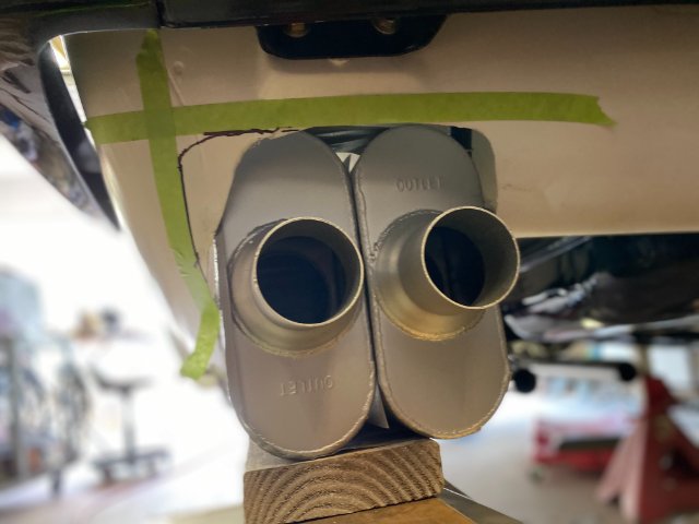
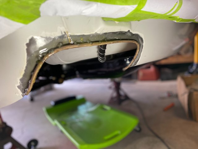
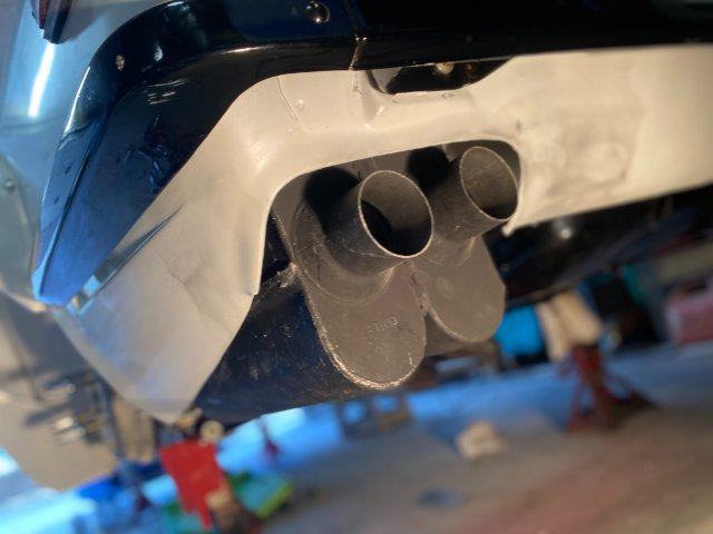
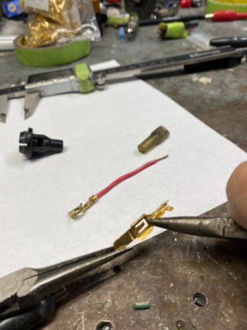
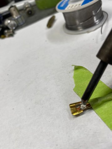
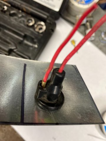
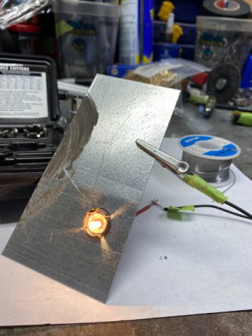
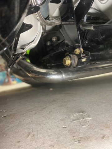
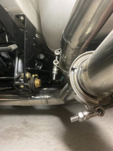
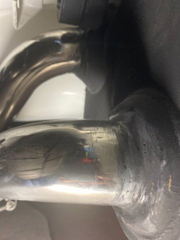
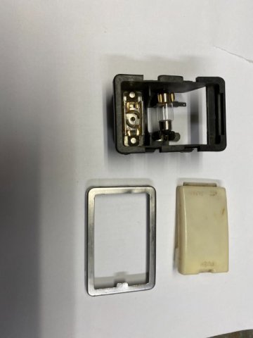
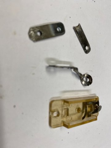
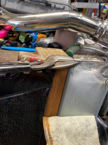
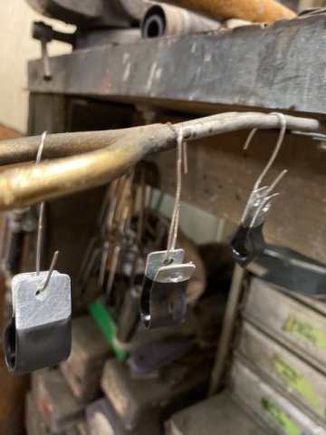
Finishing the Exhaust System- The Two Rear 2 1/4" Exhaust Pipes make Right Angles heading to the Mufflers. Midway to the Mufflers, V-Clamps connect the pipe to the Mufflers. Rear View of Rear Exhaust Pipes with V-Clamps. Exhaust Pipes are welded directly to Mufflers to provide clearance for the rear tires. I welded the Two Thrush Hush Turbo 2 1/4" Mufflers together. Note the straight 1/2" Steel Rods are the Upper Muffler Hangers. The Forward Muffler Hanger is bolts to the Rear Deck Floor Pan. Two Rubber Mounts are used because they will be supporting Two Mufflers. The Rear Muffler Mounts are also bolts to the floor pan, Two Rubber Mufflers Hangers are also use to support the mufflers. Pic of the Rubber Hangers seperately. The Two Mufflers can easily installed by pushing the Steel Stud into the Rear Mufflers. Then, lifting the Mufflers upward and pushing the Forward Rubber Mounts into the Forward Stud. Then lifting the Mufflers and insert the Flat section of the mounts onto the Floor Stud Bolts. With the Mufflers hanging from their mounts, you just have align the Two Muffler Exhaust Pipes to the Straight Exhaust Pipes under the Differential. Then, install both V-Clamps. Both Mufflers Hanging up. Rear View of Mufflers Installed. The Muffler Rear Exit Hole was completed with a little bodywork. A 3/16" Brake Tubing was bent to form the Muffler Exit Area shape. It was tacked welded to the body then Polyurethane Seam Sealer was applied to seal the both edges of the brake tubing. Body Filler was applied to smooth out the edge of the Muffler Exit. After sanding the body filler, the area was painted with White Polyuretane Paint. Repairing the Brake Light Socket in Dash Board The Brake Light Socket has a problem with its Grounding Connection. It consists of a Tiny Strip of Brass that contacts the socket hole to make Ground. This Ground Strip usually breaks off or becomes loose. I used the Terminal Retaining Strip on a 6.3 Brass Terminal(See Pic below} Note-Small Terminal Retaining in the Terminal. Using a Small Electronics Soldering Iron to solder the brass strip to the bulb socket. I tested the bulb on a piece of sheet metal with a 15mm hole to stimulate the dash board. Testing the Ground Connection. It Works!!
-
BBK and wheel choices?
toolman replied to LooseRocks's topic in Brakes, Wheels, Suspension and Chassis
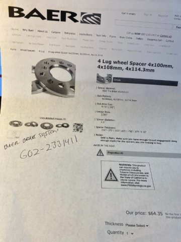
Robo, Have you tried wheel spacers to overcome your caliper interference problems? Baer Brakes has 4 X 114.3 spacers(.25",.375",.500",.625",.750",.875", 1.00") available for $70. The inner diameter is 2.50" so you so might need give a little machining for original Z front hubs. They made of Billet Aluminum so you can use them for racing if necessary. Also, you would have to use extended wheel studs. The total cost still would be minimum. Toolman
-
Heavy Duty frame rails and connectors
toolman replied to toolman's topic in Gen III & IV Chevy V8Z Tech Board
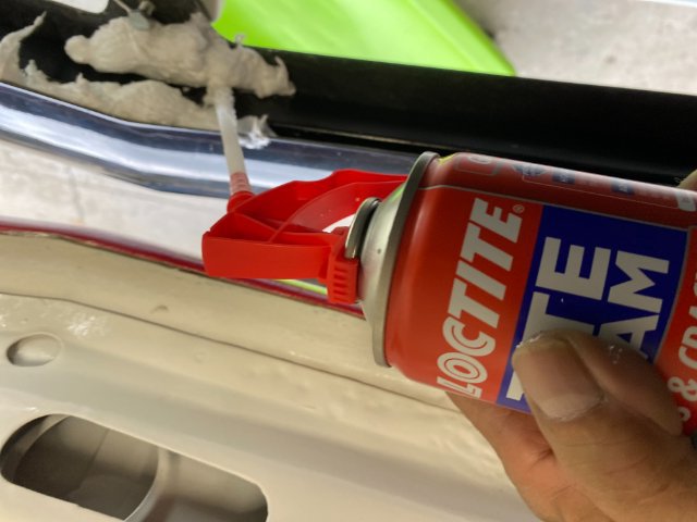
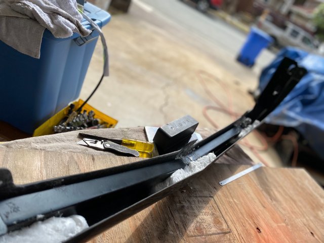
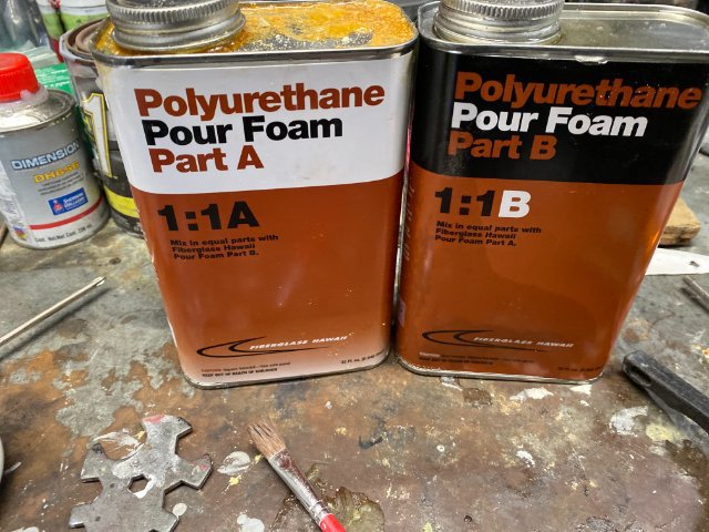
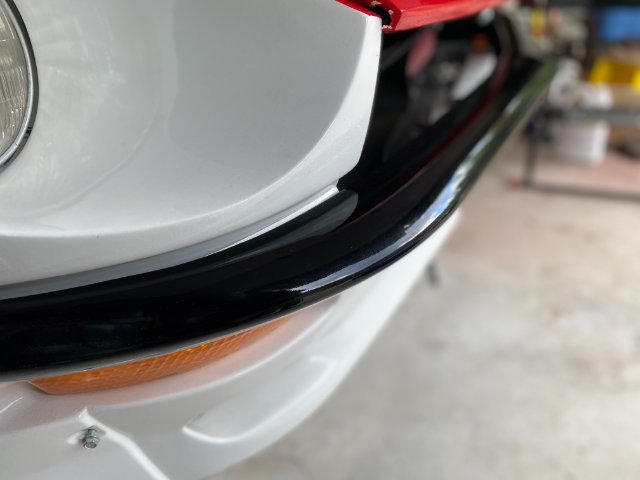
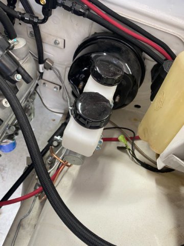
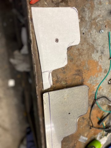
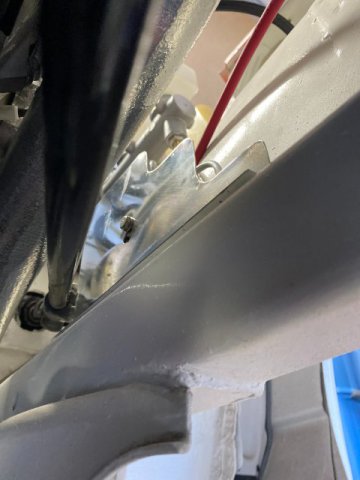
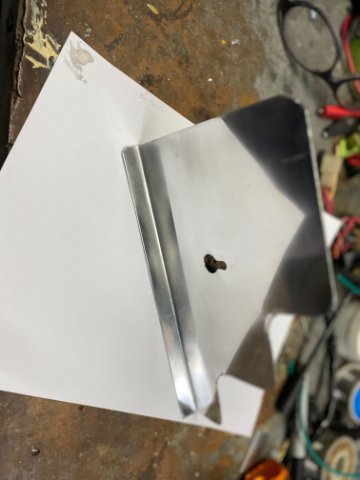
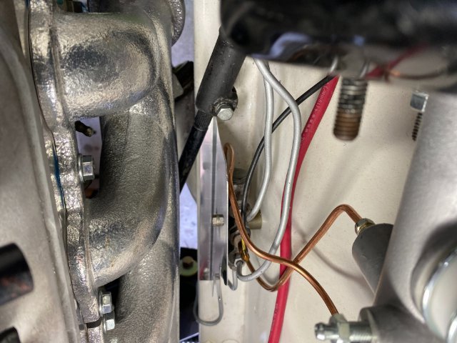
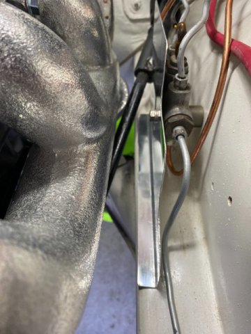
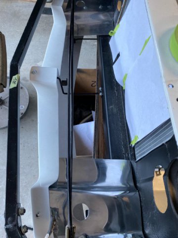
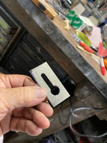
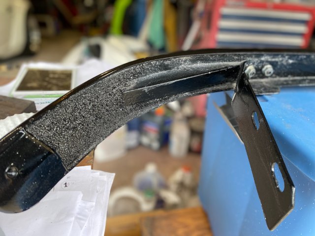
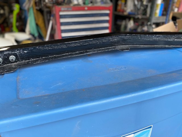
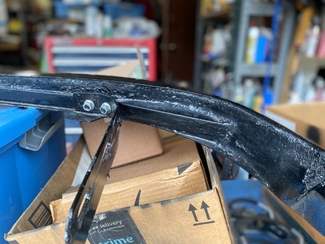
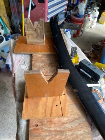
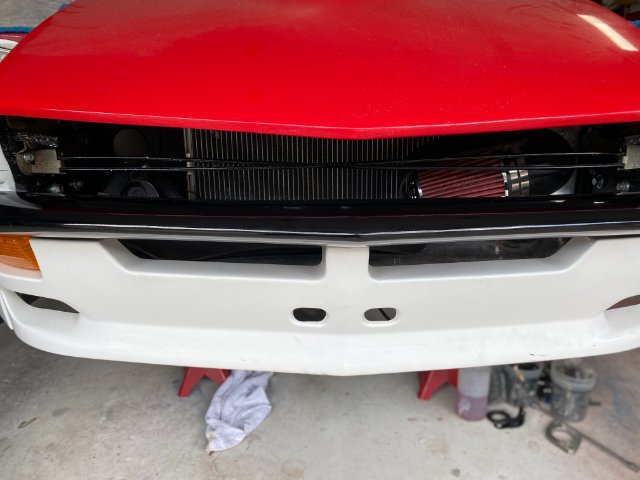
Led Flasher- I think I forgot to mention that if you are replacing the vehicle's incandescent light bulbs with LED Bulbs, you must use a LED Flasher. If you don't. the turn signal and hazard lights will not blink and will stay solid. This is because the LED bulbs will not draw sufficient amperage to cause the Flasher to heat up and blink. I got mine from Amazon for about $12. The Led Flasher came with an external ground lead too. Front Fiberglass Bumper- The Greddy Fiberglass Bumper that came with the Rocket Bunny Body Kit has just been laying on the bumper waiting for the finishing touches. Bumper reinforcement frame built from with 1" square steel tubing. The Fiberglass was first aligned with the front body panels. Locitite Tile Foam was used temporarily to hold the bumper in alignment so I could fill it with Pour Foam. But the bumper with reinforcement had to be placed in a level and vertical position with the front of bumper facing downward. Shooting the Foam to just hold the Bumper and reinforcement in alignment. Pic of the Tite Foam after expansion, it was trimmed down. Now. the Bumper was ready for the Pour Foam purchased from the local Marine Supply Store for $30). This Polyurethane Foam will fit the space between the reinforcement bar and the bumper. This will create a solid bumper instead of just a hollow fiberglass shell. To use, mix equal parts( one to one ratio) but you have only a very short time before the mixture will expand-only minutes. The foam will expand to 5 or more times the original amount. I would suggest that you mix only one spoon full to see how much the Pour Foam does expand for the first time. I made several pours instead of doing a single pour. Once the Pour Foam fully expands, you can still immediately make the next pour. I used a old hacksaw blade to trim the expanded Foam as it works better than a knife or razor blade. After triming and sanding the Foam to 3/4" from the edge of the bumper, I poured Finishing Figerglass Resin over everthing inside on the bumper. This will seal everthing up so water can not enter. This process also will strengthen the bumper although it will create addition weight. Then exterior of the bumper was painted with Gloss Black Polyurethane Paint then buffed. Back View of Left Side of Bumper Back View of Center Section of Bumper Back View of Right Side of Bumper Made two Wooden Stands to hold the Bumper in proper position for putting the Pour Foam into the Bumper Cavity. Front View of Finished Bumper Finished and Polished.. Wilwood 1" Master Cylinder Installation- The Factory Master Cylinder had a 7/8" bore and Wilwood 1" Master has a 1" bore. Its front reservoir is behind the rear reservoir so I fabricated new Master output lines. I used Napa Bendable 3/16" brake lines because the lines had to be bent in a "U" shape to go under the Brake Proportioning Valve. It is made of Nickel and Copper Steel . Also, the Wilwood Master output lines are SAE 3/8NF so I used NAPA Bendable 3/16" lines with 10mm brake nuts. Then, I cut off one end of the line and remove the Metric Line Nut and replaced it 3/8NF Brake Line Nut. Then Double Flare that end. Now, you have a Brake Line with Metric Brake Line Nuts for the Proportioning Valve side and SAE 3/8"NF on the Master cylinder side. Note-Nickel and Copper Lines different color While I was working there, I decided to construct a Heat Shield for the Brake Lines. As usual. I made a Paper Template for the Heat Shield. It was constructed out of 20 gauge Aluminum sheet. Made a Trial Model of Key Hole Bolt Hole View of Shield from bottom of the frame. Put a fold on the Shield on the bottom to add strength. Then the Shield was buffed and polished. Finished Shield. Note-A simple "KEY Hole" mount design was used. Loosening the Proportioning Valve Mounting Bolt and moving it outward slightly. Align the mounting Bolt with Round Section of the Key Hole. Then slide the Shield downward over the bolt. Tighten the bolt. A Simple Method but effective for tight spaces. Firewall Forward View of Shield Backward view of Shield.
-
Heavy Duty frame rails and connectors
toolman replied to toolman's topic in Gen III & IV Chevy V8Z Tech Board
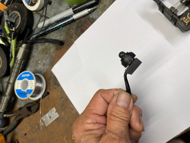
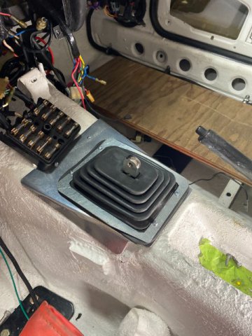
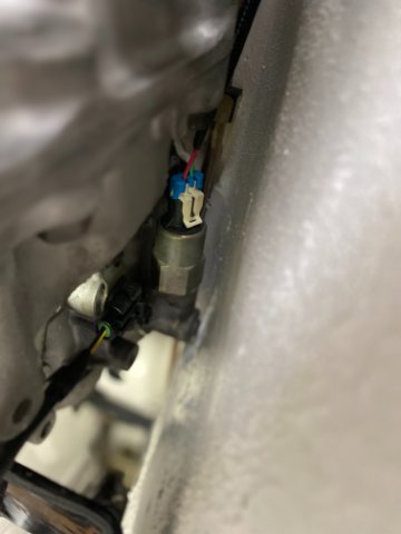
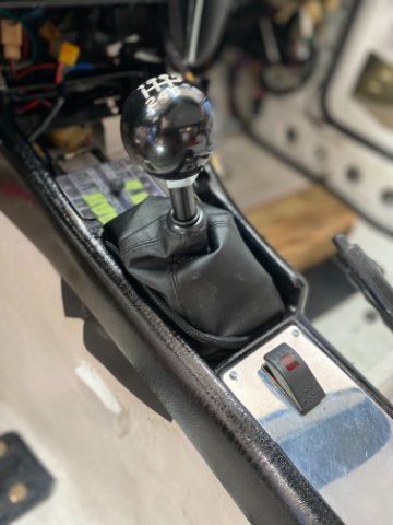
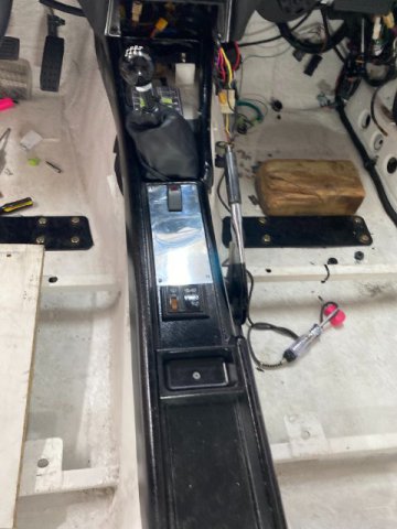
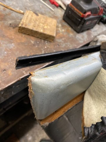
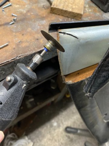
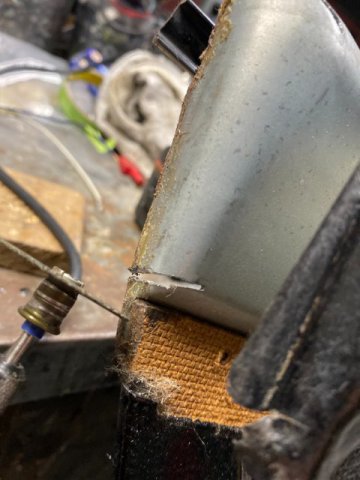
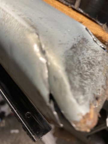
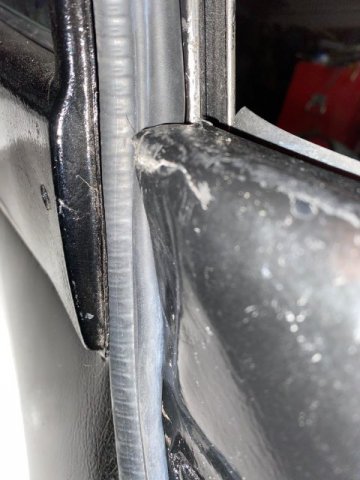
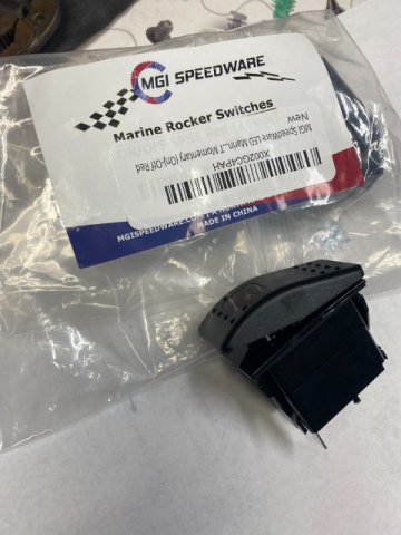
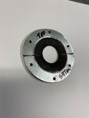
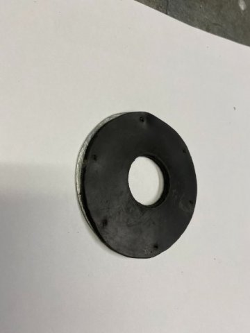
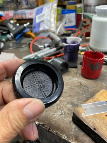
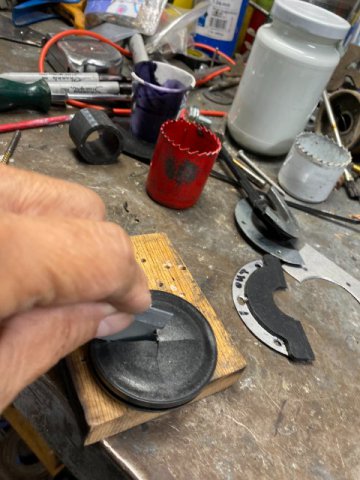
Dome Light Repair- The Original Dome Light Assembly was found to be defective when I tested it before installation. The problem was the Light Switch was not functioning. I found a 12vt Micro On/ Off Switch on Amazon for $12 for six switches. The defective switch was removed and prepared for new one. Disassembly Preparing base for new switch New Micro Switch Attached to Base with JB Weld. A LED Bulb will replace the Incandescent one later. Closup Pic of Dome Light Modifications IMG_4187.MOV Dome Light in Operation Transmission Floor Shifter Boot Cover- The Transmission Shifter Boot Cover will actually consists of two covers -Rubber and Leather ones. The Rubber One will stop Heat and Hot Air from entering the interior. The Leather One is' more of decorative reason. The Shifter Mounting Plate was constructed of 22 Gauge sheetmetal. Test Fitting of Shifter Mounting Plate Reverse Lockout Solenoid Switch- I decided to keep the Reverse Lockout Solenoid but simplify its operation. A Momentary On/Off Switch would be mounted rignt behind the Shifter. It would be located a {olished Aluminum plate on the Center Console. Operation is simple-when you want to shift into Reverse Gear, Your Left Hand will press down on the Reverse Lockout Momentary Switch( activating / openin the Lockout Gate. The Right Hand will shift the Shifter Lever to the Right Direction and Up into Reverse Gear. 12vt Water Resistant Momentary Switch (Amazon $12) Reverse Lockout Solenoid Momentary Reverse Lockout Switch on the Center Console Note-Leather Shifter Cover covering over the Rubber Shifter Cover. Note-Extra Room on Aluminum Console Plate for Future Switches( Fog Lights, Nitrous,etc) Problem with Precision Door Weatherstripping- Some other Z members also had problems with Precision Door Weatherstripping. The Precision Door Weatherstripping was made of Thick and Hard Rubber materials. When it comes across Tight Fitting Contact areas, it does not compress enough. Thus, you had to slam the doors until the weatherstripping compresses. Later model car weather stripping are made of very soft and large air pockets for compressibility. I found that major problem was at the top of the door edge meets the rear quarter glass. The Weatherstripping is squeezed into very tight area but can not compress enough to function properly. So you can replace the weatherstripping with a much softer material or increase the door gap. Since my door panels were worn and I was thinking of constructing the door panels out of 22 gauge Aluminum sheet, I tried to do some metal working on the panel. Taking off the interior covering of the upper rear corner of the panel, it was constructed a steel metal. Upper top corner of Drivers Door So if I could "flatten" this area, it might give enough room for the weatherstripping to fit. The Large Hump would have to be "slit' in couple places to allow the flattening process. A Dremel with Cut Off Wheel cut the slits. Cut another Slit on the bottom edge. Pound the area "flat" with Hammer with panel on a flat hard table. A third Slit allows more flattening. The over lapping slits were tack welded. On the Door Side, I replaced the Door Glass Vertical Upper Mounting Bolt(6mm) with a Counter Sink Phillips To gain even more space. Note-Flattening allowed the door to shut now.
-
hatepotholez, I had a similar problem with new Precision Door Weatherstripping as you. I fixed it in one day and did not spent any money on the repair. I will post how I did it in my next post -V8 Z forum Gen III & IV Chev V8Z coming soon. Check it out! Toolman
-
Heavy Duty frame rails and connectors
toolman replied to toolman's topic in Gen III & IV Chevy V8Z Tech Board
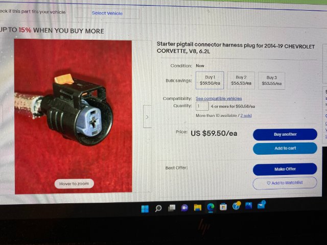
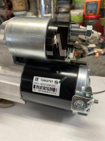
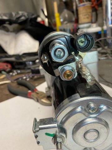
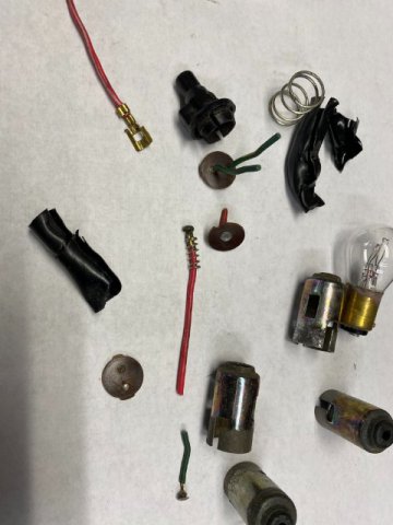
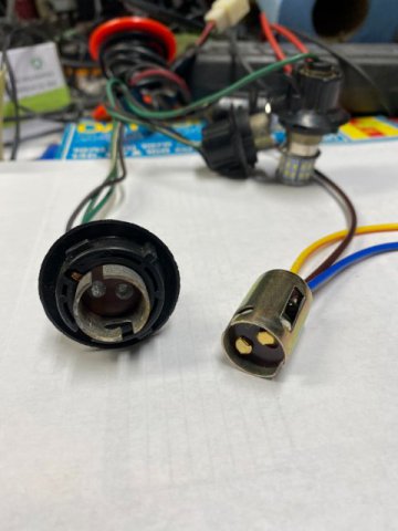
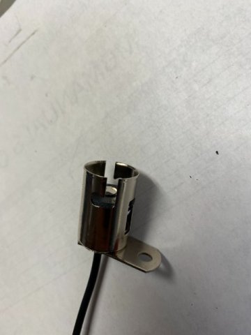
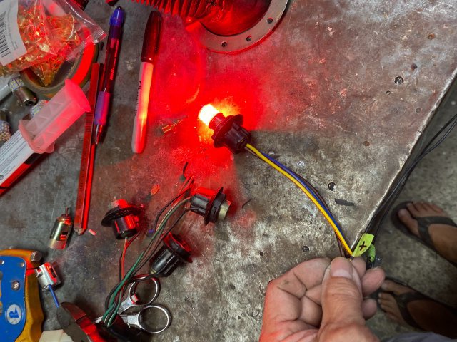
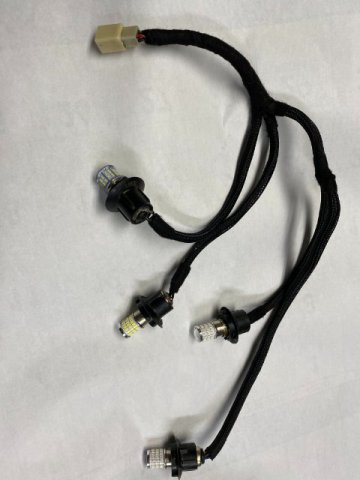
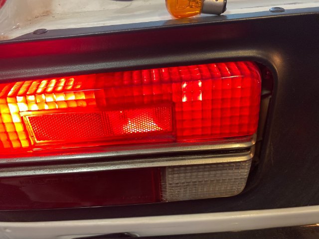
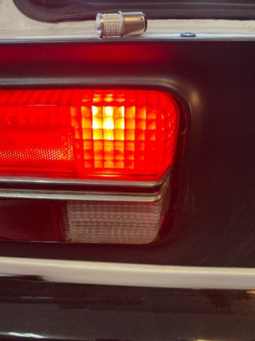
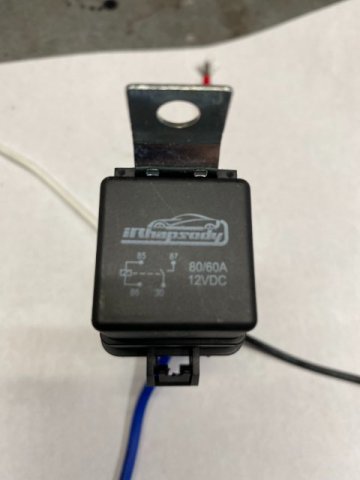
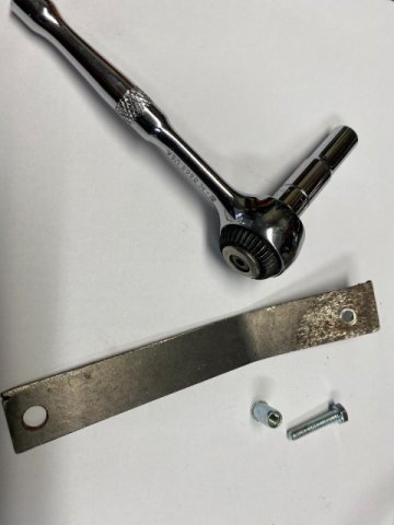
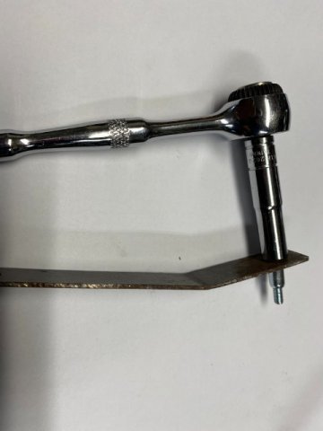
Sorry for the delayed posting, I had to do some house repairs. More Wiring to do. Starter Solenoid- My AC Delco Starter#1266257 was one of those Mitsubishi Gear Reduction ones and I was having a difficult time finding the correct Solenoid Wire for it. I ordered three different Solenoid Wires for it and all of them didn't fit. I finally found the correct one on Ebay. It was specifically for 2019-22 Camaro with a LS3 6.0L. It costs $59.00 but at least it fits. The Solenoid Lead Wire is fully insulated too. Pic of Starter and Solenoid Fuel Pump Relay- As my Holley In The Tank Fuel Pump is far away from the battery, I decided to to run a Dedicated Fuel Pump Relay. It is rated at 60-80 AMPS. I already ran a 12 Gauge Wire from the battery to the Relay in the harness. The Factory Electric Pump "Green" Wire was used to trigger to relay which will then send Full Battery Voltage to the Pump. So If I decided to upgrade the Fuel Pump to a bigger one, eveyrthing is done already. Rear Tail Lights Repair- Upon inspecting the Rear Tail Lights(Left and Right Sides) , I found corrosion on Sockets and Ground Wires on the sockets and related wiring. Disassembly of the Lamp Sockets so I decided to repair the ones that need repair or replacement. Amazon has Socket Repair Kits which contain the necessary parts and wire leads. Make to get the correct dimensions for the socket and type of sockets( two wire, one wire, two contacts one contacts, straight ears or offset ears. If the new sockets are loose in the plastic holder, you put some Hot Glue on the sockets to make them fit tight. Original Factory on Left and Replacement on Right The Single Contact Lamp Socket replacement To be used, the flat bracket must be cut off. Before connecting the Lamp Sockets to the harness, all of the Lamps were tested. Note- I went to LED Bulbs for the whole car. not just the Rear Lights. Led Lights will also lower the Amerage draw compared to the original Incandescent Bulbs. I found some White Turn Signal Connectors discolored Brown because of Overheating. Incandescent Bulb LED Bulb Finished Repaired Harness Still More Electrical Work Coming Up.
-
Heavy Duty frame rails and connectors
toolman replied to toolman's topic in Gen III & IV Chevy V8Z Tech Board
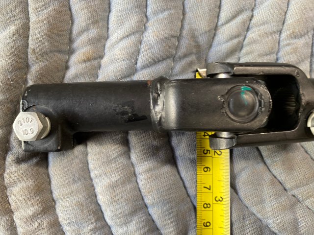
mutantZ, No, the lower section of the steering column is not made of plastic. Both factory and Silvermine columns are constructed with metal components. All modern steering columns consists of both collapsible exterior housing and steering shafts. The methods to accomplish this task may differ but the end result is the same. Collapsible steering parts must be replaced if damaged to provide same degree of protection. Even when working on these components, care must be used not to damage them (excessive force like hammering,etc). -
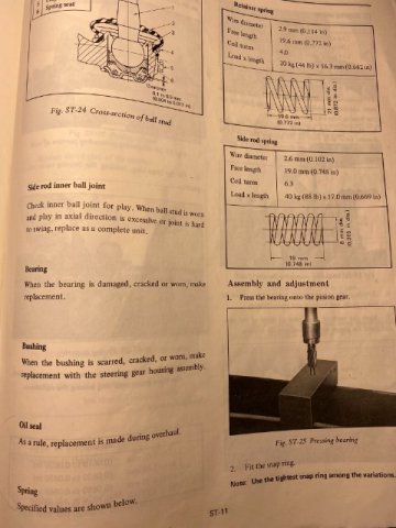
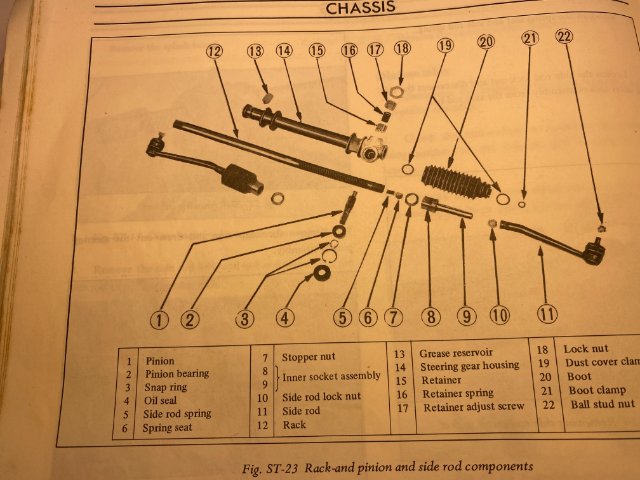
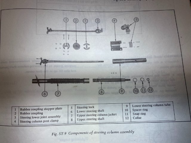
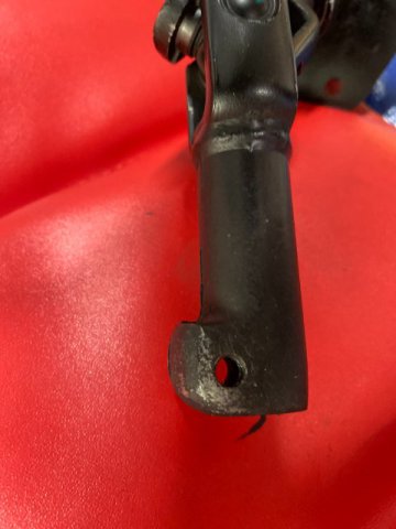
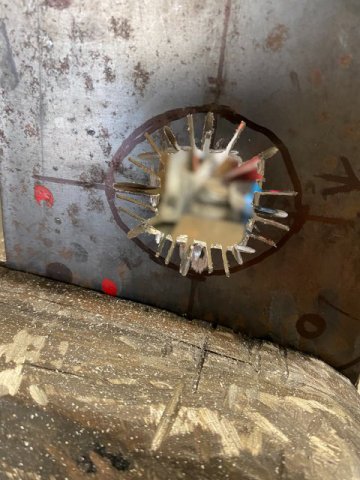
beton, Looking at the pics that you posted, Maybe this damage properly occurred previously and was then repaired. Most common repair on this type of rack and pinion is worn out INNER TIE ROD ENDS. The RACK travels in a very straight line if not. you will definitely have a "Bind" when turning the steering wheel. In this case, the Rack would be replaced. The cause could be from hitting a rock damaging Rack or Bad Accident. I am including copies of Factory Service Manual -Serving the Steering Rack pages. Does this help? Toolman
-
Heavy Duty frame rails and connectors
toolman replied to toolman's topic in Gen III & IV Chevy V8Z Tech Board
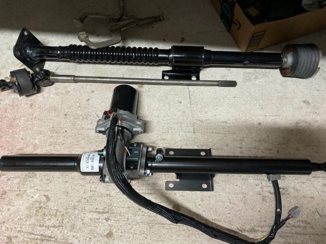
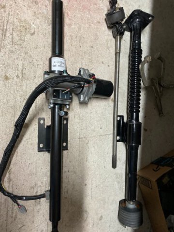
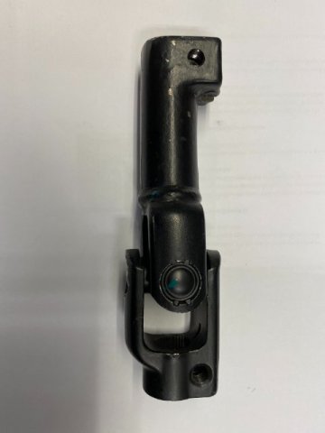
MutantZ, Here is a pic comparing Factory Steering Column vs Silvermine Power Steering Column. Note-the Collapsable Section on the Factory Column Here is pic of the Factory Column with Internal Parts Exposed. Does these pics give the information that you need? Toolman
-
Heavy Duty frame rails and connectors
toolman replied to toolman's topic in Gen III & IV Chevy V8Z Tech Board
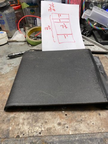
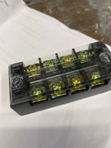
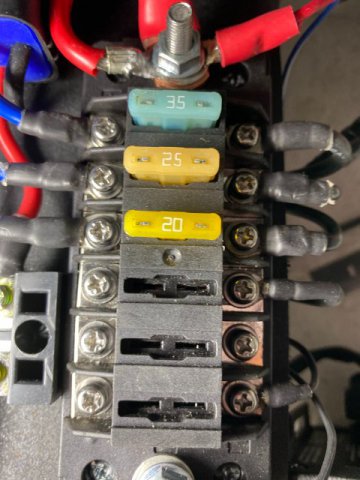
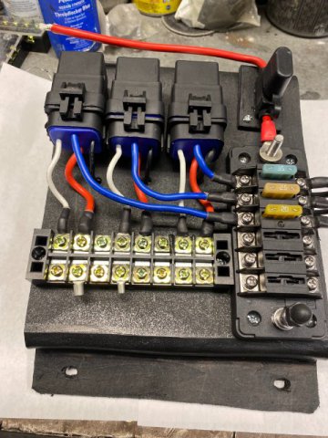
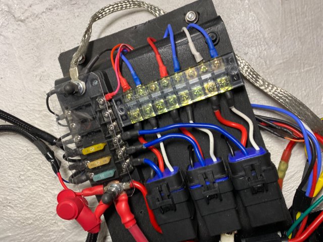
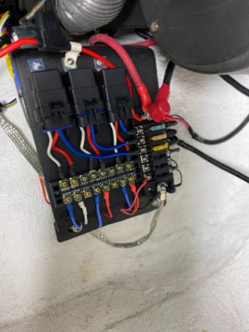
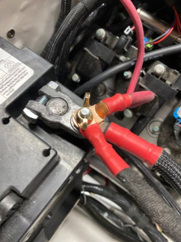
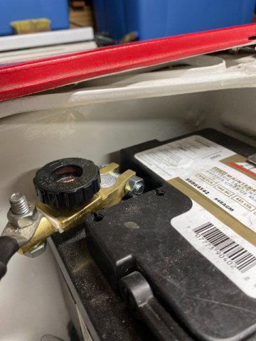
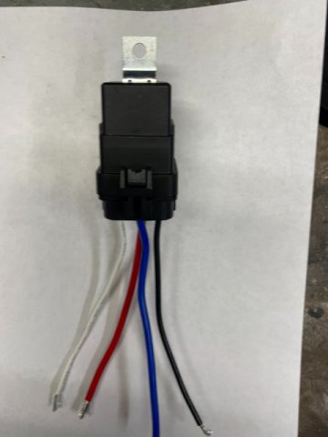
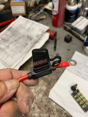
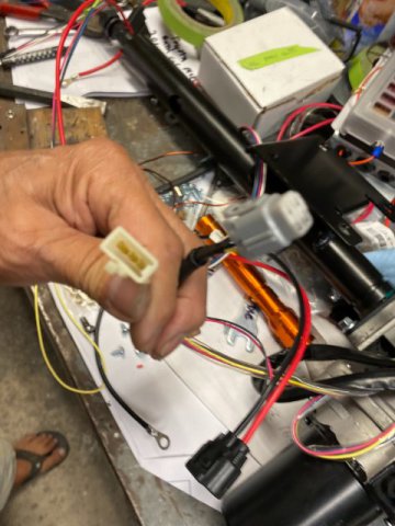
Constructing FUSE / RELAY AND JUNCTION BATTERY PANEL Because of limited engine compartment space, I decided to build a Fuse/ Relay and Battery Junction Panel in the Passenger Side of the Transmission Tunnel. The Panel was made from 1/4" Black Sheet Plastic. The Dimensions were about 7" x 10 1/2". The Legs were made to provide 1" space underneath to run wiring . The Plastic was bent by using a straight edge and 1000 Watt Heat Gun. The Basic Layout Plan for the Panel. This Diagram show wiring for Speedometer Convertor and Electric Power Steering. I use Four 80/ 60 Amp Relays as the relays will be powering more than one circuit at a time. This 4 Pin 80/60 Amp 12vt DC Waterproof Relay comes with 12 AWG insulated wires. Costs $38 for Four Relays from Amazon This pic show a 40 amp In Line Fuse Waterproof Housing with 10 Gauge wire. This In Line Fuse will used as the Terminal Fuse Block was rated at only 30 amps. This Fuse was utilized for the Electric Power Steering Motor. This Dual Rows Block Terminal Strip from Amazon costs $8 for two. This 6 Way Fuse with 5 Fused Circuits with seperayte Postive anf Negative Bus Bars costs $17 from Amazon. The top 12gauge Red Wire has a inline waterproof 40 AMP Fuse. This Fuse protects the Electric Power Steering Motor. I could not use the Fuse Block as it was rated at only 30AMPs. The White Relay wires trigger powers the Blue12vt wires that connected to the Positive Bus Bar. Then the 12volts exit the Relay through the Red Wires. Then the 12vt crosses the conection to the Output wires. The Vertical Fuses protected each circuit. The Black wires on the Right Side connect to Negative bus bar(Ground). The Top 1/4" threaded stud connects to Battery Positive terminal. The Lower 1/4" threaded stud connects to a Negative Ground strap. The Panel with the wires all connected. Note- Wires when possible are run under the panel to provide a clean appearance. Majority of the Output Wires were required Key On Operation. Some Devices like the Holley Terminator Computer, Silver Mine Power Steering required straight Battery Power but still ran thru a Fused circuit. k The Relay Panel was mounted to Transmission Tunnel with battery cables attached. A Marine 12vt Battery Cable holds cables from the Relay Panel,Alternator and Starter Motor. The Negative Cable attaches with a Post Master Quik Disconnect Switch. It can be disconnected with just a twist of the Black Knob. Costs $14 from Amazon More Wiring to come.
-
Where are you hiding your wires?
toolman replied to mutantZ's topic in S30 Series - 240z, 260z, 280z
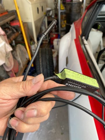
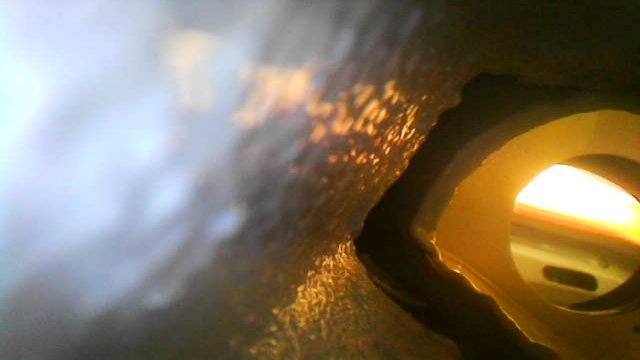
mutantZ, i used my 6 foot Borescope that I bought from Amazon for about $30 to check out those Air Inlet Tubes. Here is a pic from the Borescope -from the Right Side Kick Panel Hole looking forward to the Core Support. I live in East Oahu near Hananuma Bay.
-
Where are you hiding your wires?
toolman replied to mutantZ's topic in S30 Series - 240z, 260z, 280z
mutantZ, Have you considered putting your engine compartment wiring into the Left and Right Air Interior Ventilation Tubes? The tubes run all the way from the Core Support to the Interior Compartment (above the Kick Panels). The tubes are smaller at the front but large past the Strut Towers. I ran my borescope through the tubes to check them out. They were pretty clear. Also, you could put wiring in the Cowl Section( windsheild wiper area) for wiring that needs to go from side to side. With this method you could practically "hide" all of your wiring . I hope this helps you. Toolman -
Heavy Duty frame rails and connectors
toolman replied to toolman's topic in Gen III & IV Chevy V8Z Tech Board
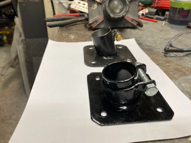
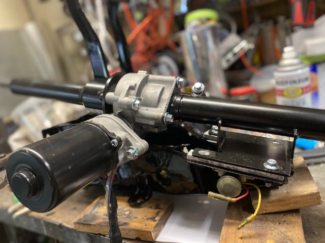
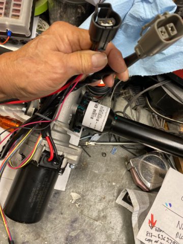
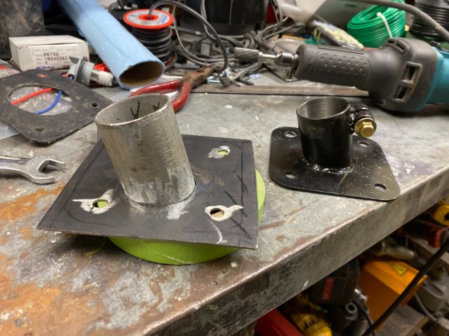
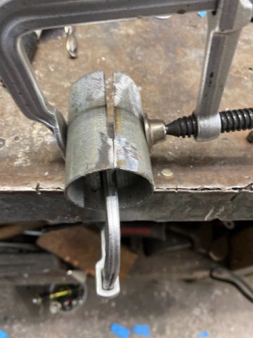
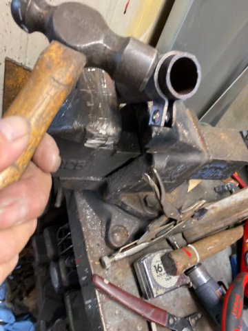
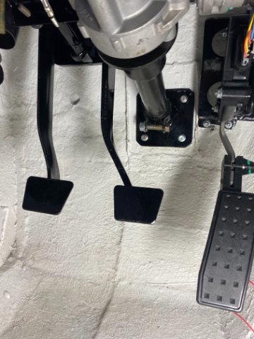
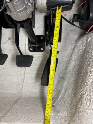
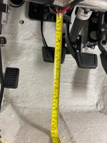
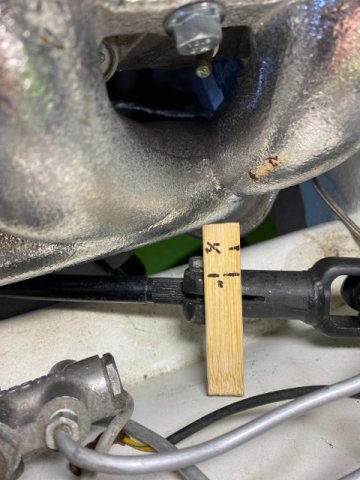
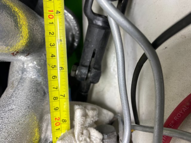
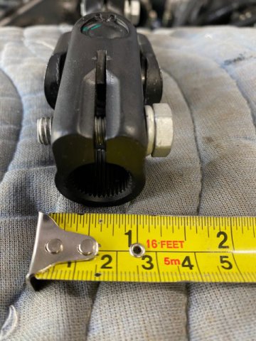
240Z Power Steering Installation- As I planned to have wide wheels and tires, power steering is almost a necessity in tight driving areas. There are BMW 318 hydraulic racks have successively installed in 240Zs. These racks are difficult to find and require different outer tie rod ends. Also, mounts for the conversion racks must be modified. There are two Electric Power Steering kits available for 240zs-Z Power Steering and Silvermine Motorsports. Z Power Steering requires you to send them your steering column to modify. Cost about $800 + Freight. Silvermine Motorsports Powering Steering is ready to install but costs $1250 + Freight. Considering all the factors. I chose the Silvermine Power Steering Unit. Silvermine Unit on the Left and Factory on the Right Wiring for the Steering Unit Plug in Connectors for Control Box Installation of the Steering Column takes normally about 2 to 3 hours. I decided to modify the Brake/ Clutch PedalMounting Bracket to allow the Motor to move a total of 180 degrees for additional leg clearance. Also, Offsetting the Steering Column Firewall Mount created additional e steering shaft to motor clearance. Made a Template for modifying the Steering Shaft Mount on the Firewall. Note- The Hole for the Steering Shaft Mount Plate is not round. It is actually an "Oval" similar shape. When a Round Tube passes through a Flat Plane at an Angle, it creates an Oval Hole. If you just drill a Round Hole, there would be large gaps around the edges that would need to be filled in. New Steering Column Mount alongside of Silvermine Mount. This Modification shifts the Steering Shaft to the Left !/4" for extra Steering Shaft Clearance. Modified Mount shown next to Silvermine Mount. Fabricating Mount Sleeve out of 1 1/2" tubing. Bending 3/16" steel strip to make the Steering Column Clamp. Finished with Gloss Black Powder Coating Steering Shaft Adaptor Shaft Adaptor Modified by rounding off its edges eliminating stress points. The Pedal Mounting Bracket was notched on the Right Side to allow the motor to swing up to provide more leg clearance. The Notch was reinforced by adding 1/8" steel plate around it. Also,an additional lip was added to give the area more strength. .View of the Modified Pedal Mounting Bracket with Steering Column on it. Interior View of Mounted Steering Column -Note its offset position I ended up leaving the Power Steering Motor in the Right Side of the Column. This position would provide the most clearance for both my leg( left and right) movements. Engine Compartment view of Steering Shaft Clearance to Motor. Had about 3/8 to 1/2" Clearance . Silvermine Power Steering Control Box was mounted to Driver Side Kick Panel. Detailed Measurements- With the Motor on Right Side of the Column, Distance between motor and floor is 14 1/4" , With the Motor on Left Side of the Column, Distance between Motor and Floor is 14 1/2" Distance between exhaust manifold and steering shaft is 1/2". Distance between Firewall and Bolt in Steering Shaft Adaptor is 6". Splined End of the Shaft Adaptor Side View of Shaft Adaptor Next-Building Fuse and Relay Panel
-
Heavy Duty frame rails and connectors
toolman replied to toolman's topic in Gen III & IV Chevy V8Z Tech Board
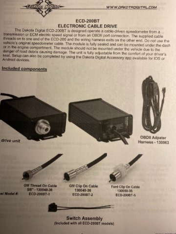
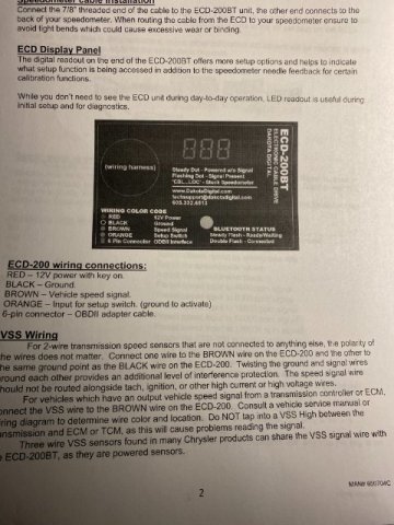
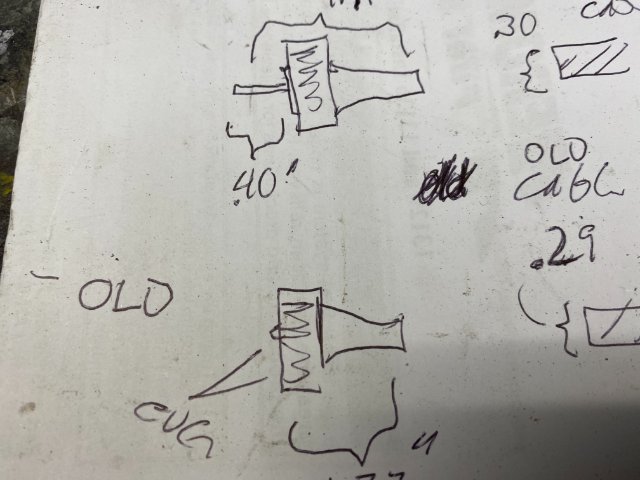
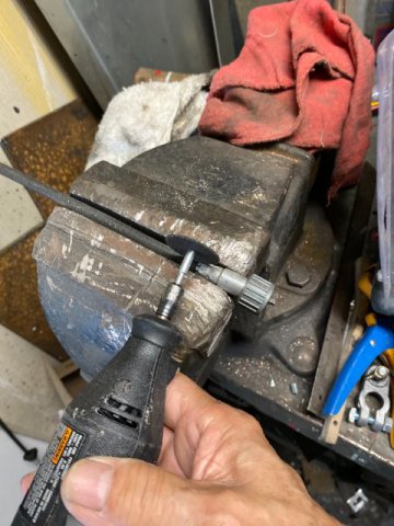
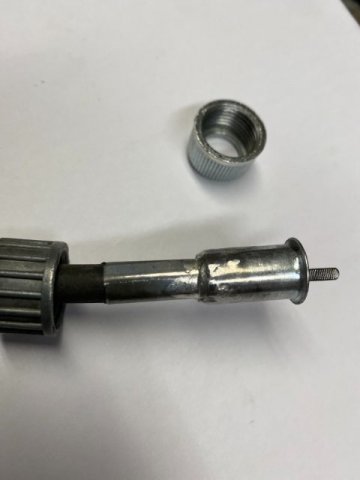
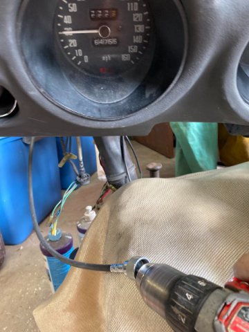
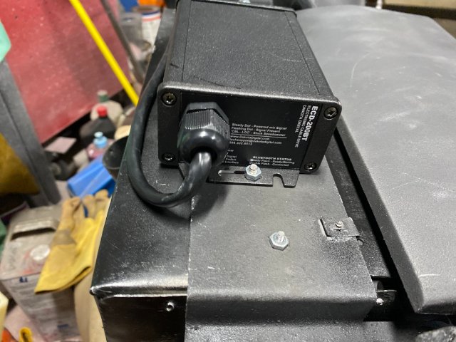
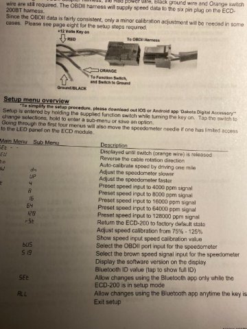
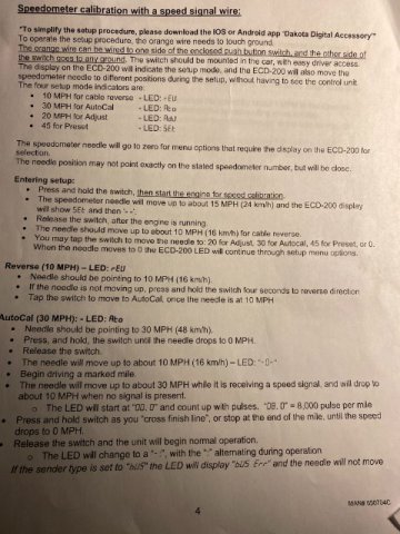
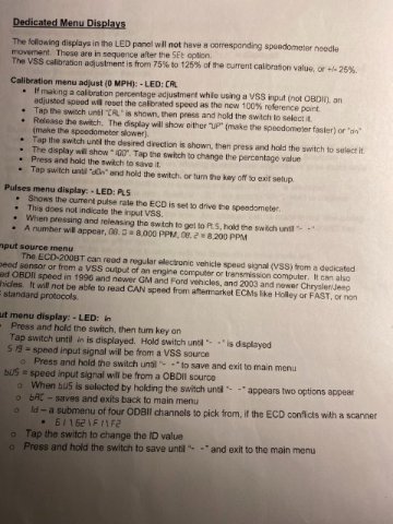
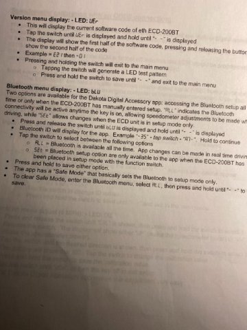
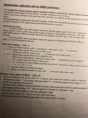
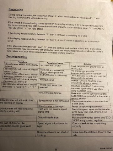
Speedometer Modifications- There are Three Options to get a working Speedometer with LS Swap 240Z. First , Keep the Original Z speedometer and convert your T56 trans to Manual Speedometer. This option requires sending the trans rear extension housing to be machined to handle "old type" plastic speedometer gearing. There is a place in Washinton State that does this work for about $400 and you have to ship it to them. Second option is to replacinging the original Z Speedometer Unit with a new GPS Speedometer. This method may require modifying the dashboard to install because of size differences. Also, GPS would not function in tunnels. Cost about $300. The Third option is utilizing an Electronic Speedometer to Manual Speedometer Conversion Kit. These kits convert the VSS ( Vehicle Speed Sensor) signal to an electronic motor in a control box. A cable from this box drives a cable to Z Speedometer. Advantages of these kits are One Day Installation Time and Easy Recalibration when changing tire sizes and rear differential gearing. Cost about $329. I chose the Dakota Digital ECD-200BT-1. This model has a GM (old style) threaded collar speedometer cable. Note-Different cable versions Although the GM Threaded Cable is very similar to the Datsun Z cable, it does not screw on but it is very close,though). So you must perform a little fab work to make it fit. First, I measure the cable measurements of the 240z cable. The Most important measurement is the speedometer stick out from the housing. Now, you cut the 240z threaded sleeve off with a Dremel with Cutoff Saw Blade. I used a piece of 1/4" thin tubing (about 2" off of a Acid Brush Handle) and Silver Soldered to 240z cable cup section. Silver Solder melts at 300 degrees but provides a very strong weld. This modified section was then slipped over the Dakota Digital cable after removing its section with the Dermel too. Then the modified section attached to the Dakota Cable with JB Weld. Set the cable stick out to the previous measurement. Remember to allow the JB weld to cure 24 hours before using. 240z Cable Threaded Sleeve installed on Dakota Digital cable with minor surgery. The Dakota Digital cable was tested with a Cordless Drill running in Reverse Direction. Note-Speedometer Needle moving at speed. The Cable Drive Unit was attached to under the Glove Compartment. Pic of Dakota Digital Speedometer Cable hooked up to Z Speedometer. The following pics are more information on Dakota Digital Speedometer Conversion Kit. Next 240Z Power Steering Installation
-
Heavy Duty frame rails and connectors
toolman replied to toolman's topic in Gen III & IV Chevy V8Z Tech Board
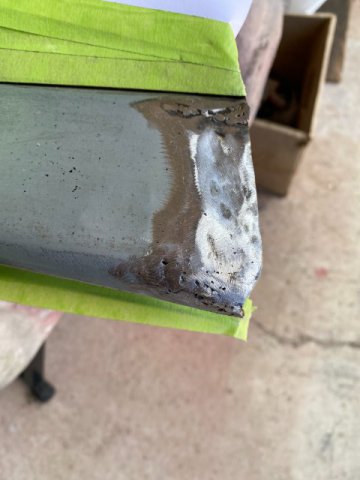
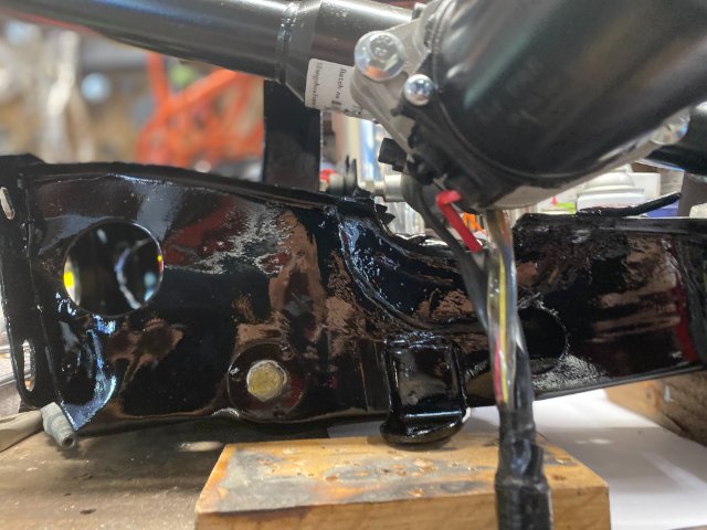
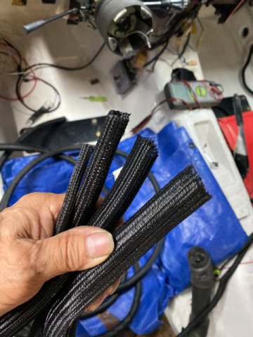
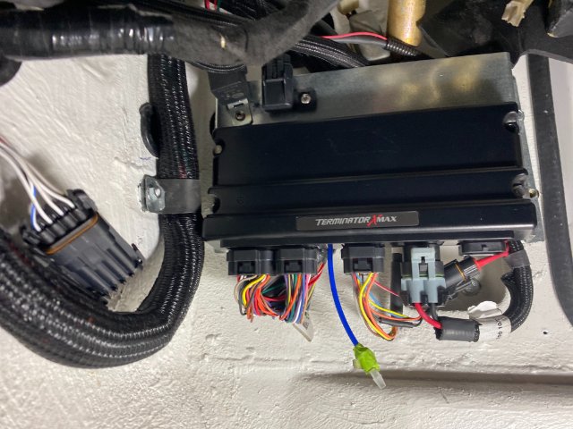
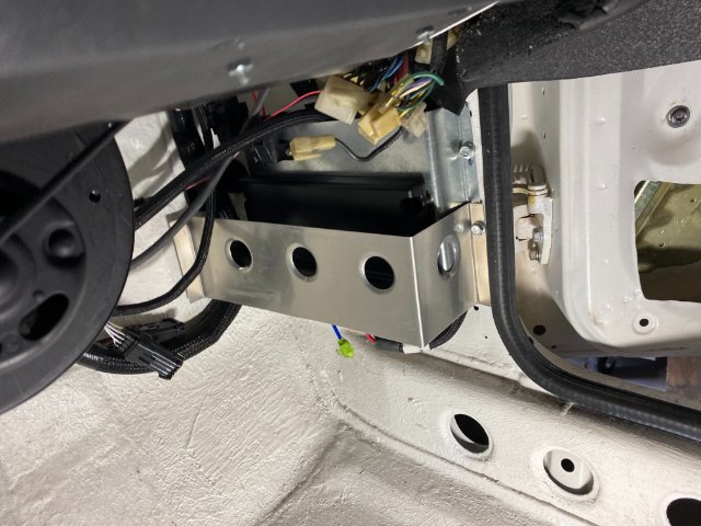
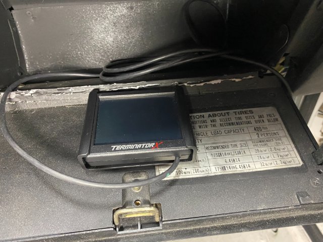
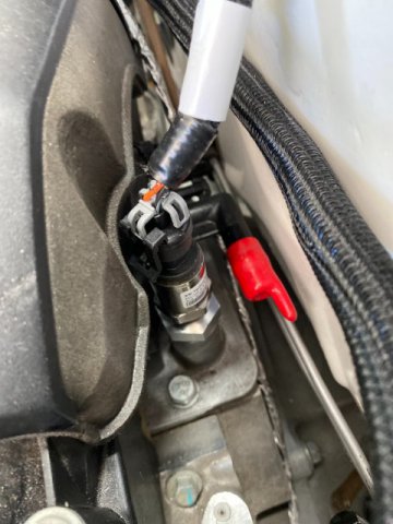
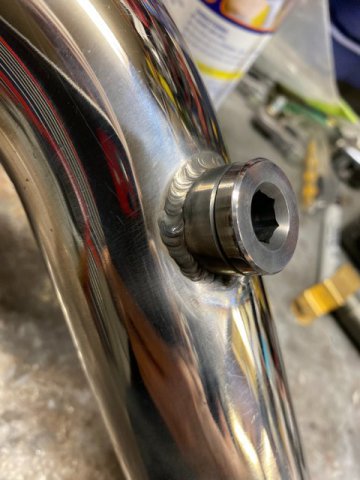
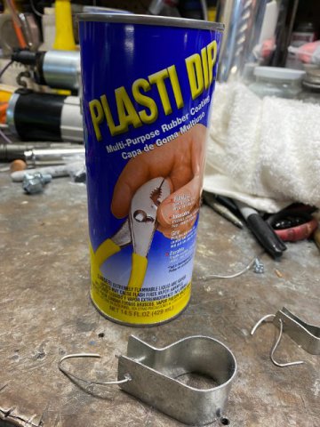
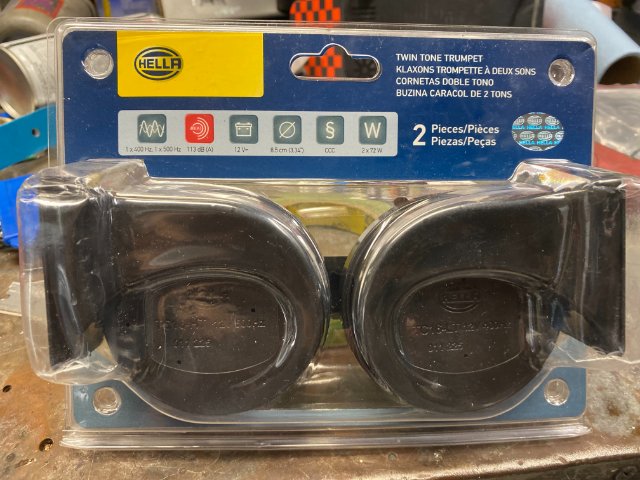
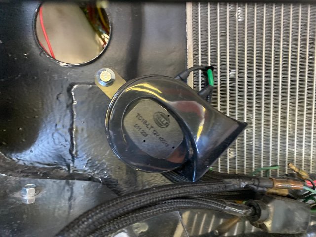
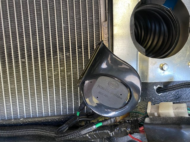
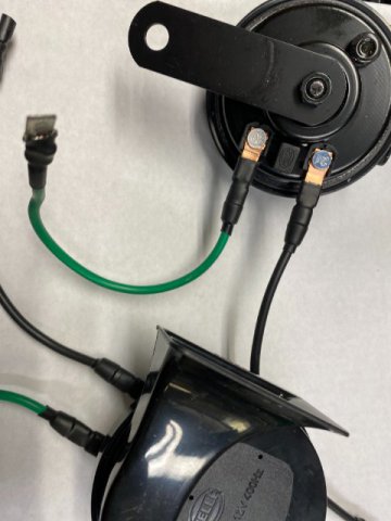
Sorry for the delay in posting, my PC broke down over the week end and tried to fix it. But ended up getting a new one at Costco. Wiring Harness Mounts- Since there were so many different sizes harness mounts necessary, I decided to construct my own. I used 22 gauge steel metal with 3/4" to 1" strips. Plastic Dip which a Black Plastic Protective Cover used to create no-slip handle covers for hand tools. Procedure is slowly dip the items into the can to add the coatings on. It works better by dipping multiple times instead trying to make one heavy coating. I dipped the mounts in about three to four times( allow 30 minutes drying time between coats) to get thick but smooth coatings. Let it dry completely dry for 24 hours before using. I used Metric Nut Inserts to hold the harness mounts and found that some locations were too tight to use the normal Thread Insert Rivet Pliers. So I constructed a simple tool to do this job in "Real Tight Places. Used !/8" x 3/4" x 8" mild steel plate with 1/4" hole drilled in one end. Just inset a 4MM insert insert in the hole and place the right size bolt on the 4MM insert. Then, just tighten the bolt and it will squeeze the nutsert tight. In REAL TIGHT PLACES, you can use a Hand Wrench instead of a ratchet and socket. It takes longer but it will work too. Wiring Harness Looms Previously I used Flexible Plastic Split Opening Wiring Looms but found out these looms would hold water and debris in them. So now, First, Premium Scotch Brand Black Electric Tape was wrapped tightly over the wire harness. Then Alex Tech Split Sleeve Wiring Looms were installed over that. This braided covering is very tear resistant but allow water to drain out. , ALEX TECH SPLIT SLEEVING is sold on Amazon with !/4", 1/2",3/4" and 1" tubing sizes. Note-After cutting the ends off, it is recommended that a mini torch be used to burn the ends slightly to prevent ends from coming apart. The ends can be taped with electrical tape or use Heat Shrink tubing to hold the ends down. I noticed that even factory wiring comes with this type of looms. Holley Terminator Computer Installation The Holley Terminator Computer was installed on the Passenger Side Kick Panel with fabricated mount. Note-Wiring harness Mounting Clamp holding the harness it the firewall. A 1/8" Aluminum Protective Plate was added to bottom area of the computer to prevent damage to the wiring. The Computer Maintenance LED Lights are located on the top of the computer so are still visible in this location. The computer mount was built with 1" clearance for the wiring to allow wiring to go underneath. The Holley 3 1/2" LED Touch Screen Display was stored in the Glove Compartment. It will be used to tune the computer. Holley Universal Oil Pressure Transducer The Factory LS3 Oil Pressure Sender will not function with the Holley Computer so the Holley Oil Pressure Transducer must be utilized. Cost $140 from Amazon. Holley Included the Oxygen Sensor Bung that must be welded in the Front Exhaust pipe after the exhaust manifold. Horn installation- A pair of Hella Toyota Horns ( Amazon $30) Horns were mounted using existing radiator lower mounting bolts, Right side Horn Left side Horn Next-T56 Transmission Electronic Speed Sensor to 240z Manual Speedometer Conversion Kit
-
I tried for a couple of days to reset my password. It said that confirmation would be sent to my email address but I still have not received any emails from this site. I checked even junk mail box ,too. Thanks, Toolman
-
5 Star Rising, I hate to be the bearer of "Bad News" but if your measurements are correct, a proper repair is beyond most home mechanics. I am a ASE Certified Automotive Body and Paint Repairman. Your damage is to great to just slot brackets and achieve proper alignment. I would say your best best is get a repair estimate from a Body Shop in your area. But fixing the car and not damaging the paint job might not not be possible. I hope this advise helps.
-
Heavy Duty frame rails and connectors
toolman replied to toolman's topic in Gen III & IV Chevy V8Z Tech Board
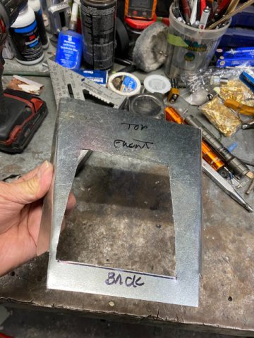
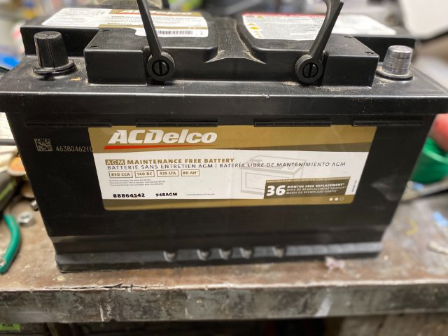
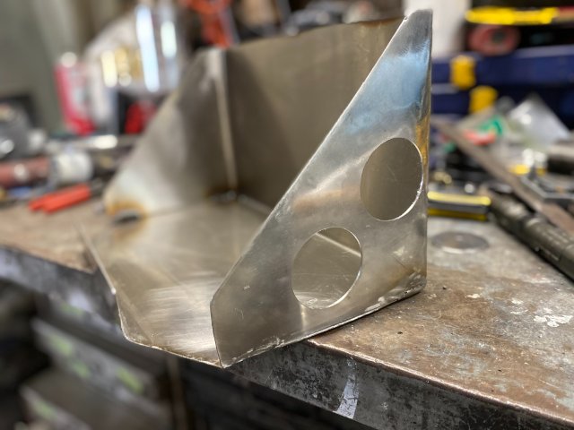
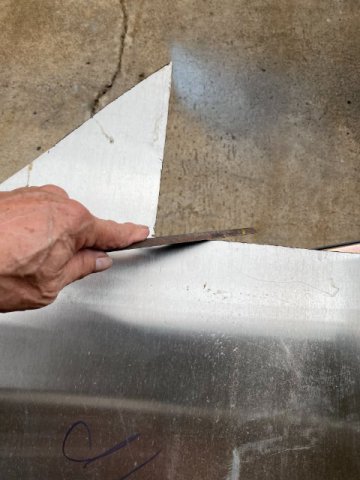
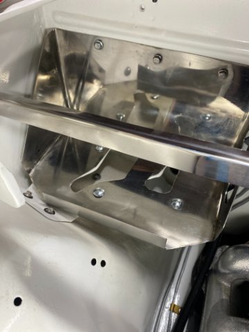
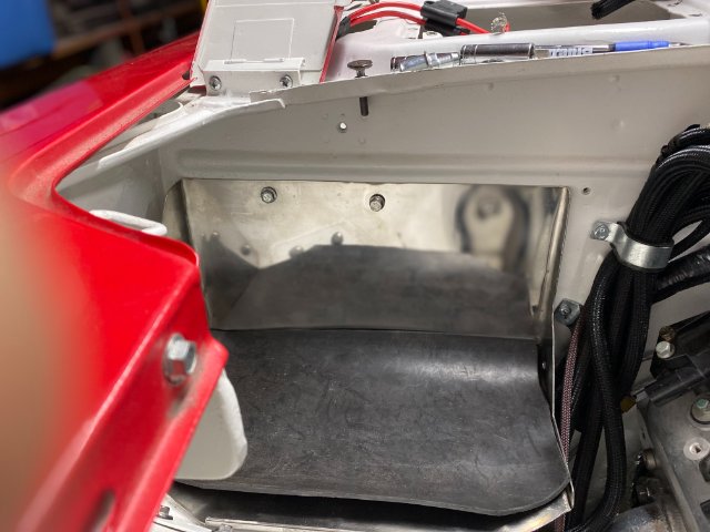
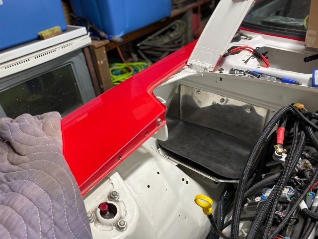
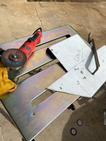
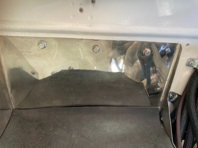
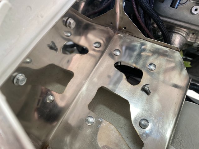
Battery Box Modifications- This is the Delco Replacement Battery for a 2019 Chevrolet Corvette 6.0L LS3. It is a GelCell Battery rated at 900CCA but weighs 49 pounds. Because of its weight and size, I decided to beef up the original Battery Tray. Making a Paper Template of New Battery Tray I decided to construct the Battery Box out of 16 gauge Stainless Steel. Used Right Angle Grinder with cutoff wheel to cut the Stainless Steel. Filing down the sharp edges from cutting. After Bending the Stainless Steel and tack welding the two front corners, the Battery Box looked like this. Front View Added two Holes on side for Improved Appearance. Made a Paper Template to locate the Mounting Holes for the Battery Box. Template taped the Bottom of the Battery Box to locate holes to be drilled. Three 6mm bolt and nuts installed in Firewall to support the Box. A 1/8" steel bar was installed in the window cowl to reinforce the three bolts in the firewall. Four 5/16" Carriage Bolts and nuts secured the Box to existing Battery Tray. The Box was polished with Buffing wheel. Battery Box Version-1 Front View Battery Box with Stainless Steel Hold Down Bolts. Unfortunately, when I tried to put the Delco Battery into the New Battery Box, it would not go in. The Left Side Box Wall prevented the Battery from sliding in. So that Wall had to be removed. Modified Battery Box Version-2 With a 1/4" Rubber Mat on bottom to absorb vibration. Another Angle view of the Battery Box. This Second Version shows no matter how careful you plan something, it can go wrong. So You must be able to adapt and continue. Next-More Wiring to do
-
Heavy Duty frame rails and connectors
toolman replied to toolman's topic in Gen III & IV Chevy V8Z Tech Board
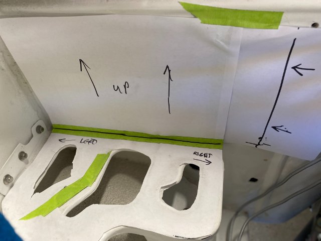
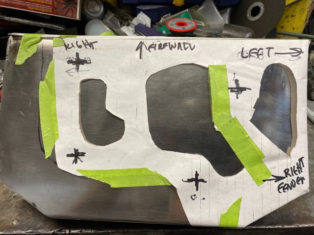
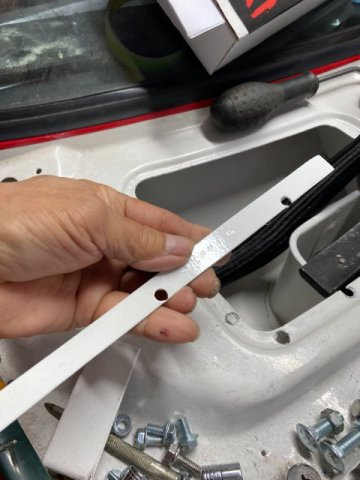
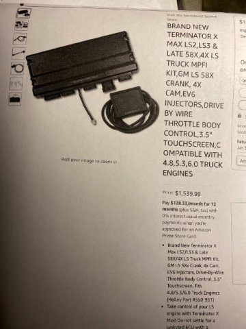
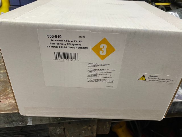
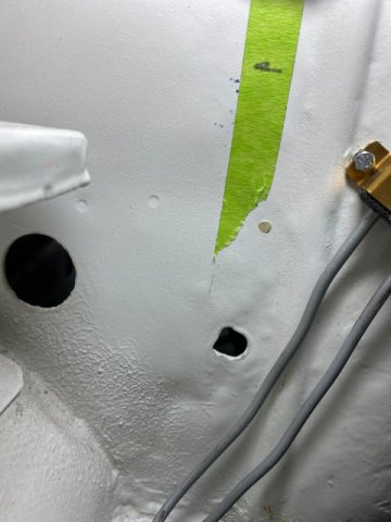
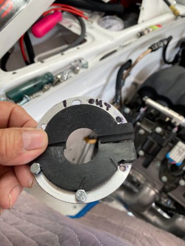
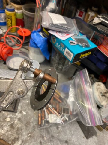
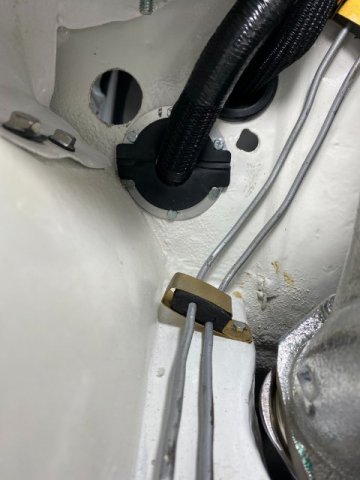
Change of Plans- I must have been a "Good Boy" because my Ungraded Holley Terminator X Max arrived on Christmas Eve. Brand New Holley Terminator X Max# 555550-910 was designed for Late Model LS3 motor with 58 CAM, EV6 Injectors, Drive by Wire Throttle Body and a Remote 3.5 Touch Screen Turner was $1540 from Amazon. I started by laying the Holley harness over the motor and attaching the sensors. Everything pretty much lined up but there were wires which were a little short. But no big deal. A little shifting of harness around and removing the tape on the looms to gain an inch or so. Then,retaping the hareness. With the harness laid out, I could tell the major problem would be getting the harness through the firewall to connect to the computer. The area between the Battery Tray and Firewall was the only place where everything would fit. Local Reconstruction Law did not allow relocating the battery into the rear of the car. Although that location would make harness routing much easier with no battery in the way. Plus, Weight Distribution would be better too. This was a small Area for alot of wiring to pass through. The holes under the battery tray was for the AC Hoses to pass thu. I found this Split-Seal Grommets that was big enough but stll provide good sealing qualities. But they costed $35 each from Amazon. seal Note- The Split-Seal has extra sealing lip at the joint. It provides a little more joint sealing. I also made an additional sheet metal ring to reinforce the seal from the interior side of the seal. The Split Seal and Reinforcing Ring was bolted together with six 4MM bolts and nuts. Cleco Pins were utilized to position the seal while installing. Engine Compartment View-Seal installed with harness going through the Firewall. f Interior View of Split Seal installed. Aluminum Templates with various hole sizes were used to determine correct hole to be drilled in the Firewall. The biggest objects on the harness were the various relays so the hole had to be at least this diameter so the harness could fit thu. In case you need a custom Grommet , this is the procedure to construct one. Cut out 23 gauge sheet metal to create the Outer Frame. Use a razor or knife to make the Round Seal out of 1/8" rubber sheet. . Finish shaping and use Contact Cement to attach Rubber Seal to frame. Then drill six Mounting Holes and cut seal in half. If additional sealing is needed, just make an additional rubber seal on the Interior Side of the seal. Note-It is important to make the Center Sealing Hole slightly smaller to provide a tight fit with harness. For Grommets for other Small Wires, you can use Grommets (from Home Depot). Use the ones made specifically for certain size sheet metal hole. These seals are usually made of for use in sheel metal holes but check to be sure. If you want a tight fit for individual wires, drill slightly larger holes than wire diameter and push wires thu individual holes instead of just slitting the grommets. This method provides tighter sealing fit. Next-Battery Box
-
Heavy Duty frame rails and connectors
toolman replied to toolman's topic in Gen III & IV Chevy V8Z Tech Board
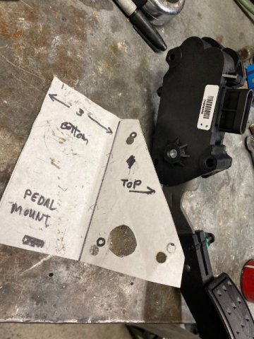
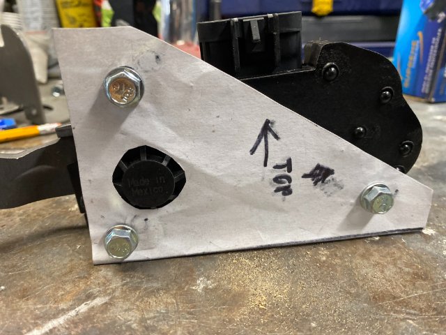
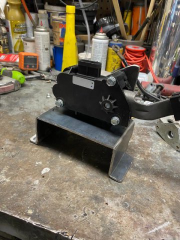
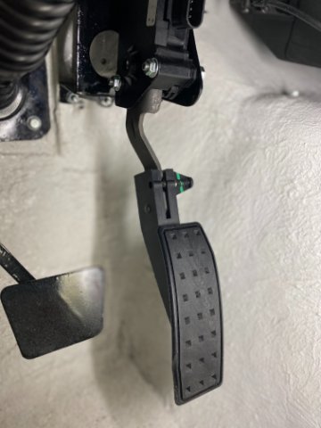
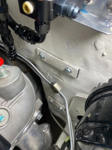
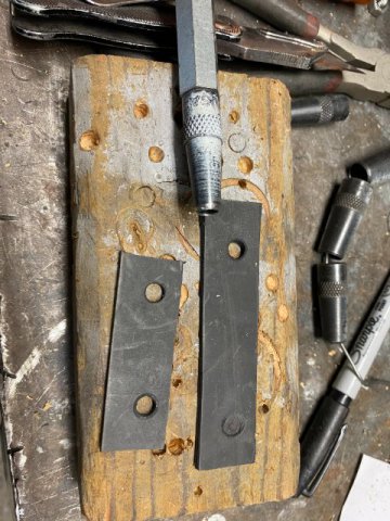
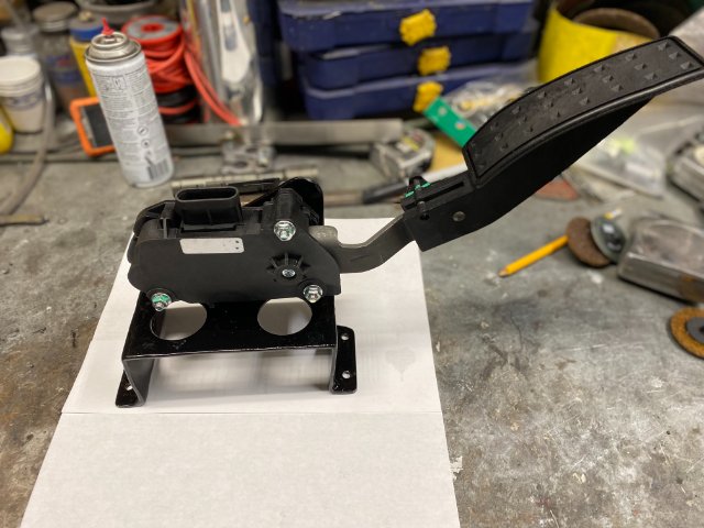
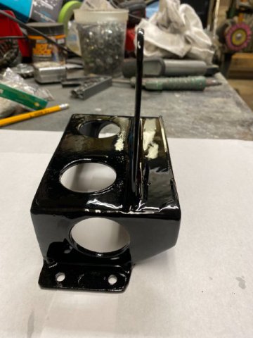
I was planning to post about installing the Holley Terminator X Engine Control Kit but at the last moment I decided to go to a upgraded version of the Holley Kit. So that may take a couple of weeks to arrive because of the Pandemic and Christmas. but there are still plenty work to do. Drive By Wire Accelerator Pedal Installation- Holley recommends using AC Delco # 10379038 Pedal Assembly( Amazon-$88. However, you have to fabricate your own mount. Normally, accelerator pedal were easy to fab as they were usually constructed of 3/8"-7/16" steel rod. One could just heat the rod red hot and bend it as necessary. However, Electronic Throttle Pedals are constructed of 16 gauge metal and plastic pedal arms. Thus, fabrication of the pedal mount is a lot more difficult. Also, the location of the pedal is in a confined area next to the trans tunnel. Originally, the pedal would be attached to this plate on the firewall with three screws. I made paper templates to create the Pedal Mount. Cutting 1/8" Steel with a 4 1/2" angle grinder with 1/32" cutoff wheels. A Trial Fit of Mount. Left side view top view of mount-looking downward After Trial Fitting, the Mount was mig welded and powder coated Black. Left Side View Right Side View Holes were added to lighten the mount and looks good too. Top View Pedal Assembly Mounted Pedal Mount installed on Firewall Mount is attached with four 6mm bolts with 1/2" x 4" 1/8" steel plates on the engine compartment side of the firewall. Rubber Gaskets were made and placed under those plates to prevent water leakage. A Hole Punch was utilized to punch mounting holes. Next-Battery Box Happy Holidays to All!!
-
Heavy Duty frame rails and connectors
toolman replied to toolman's topic in Gen III & IV Chevy V8Z Tech Board
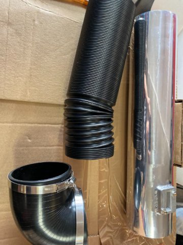
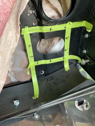
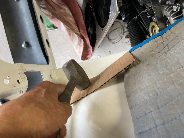
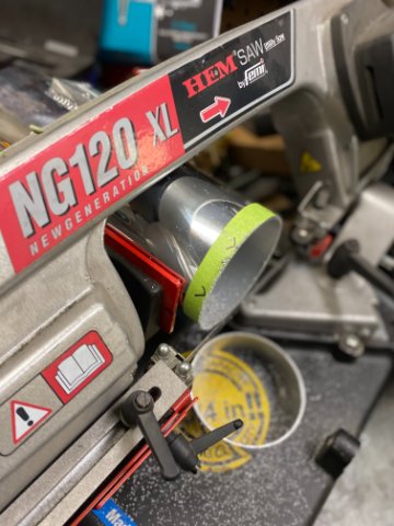
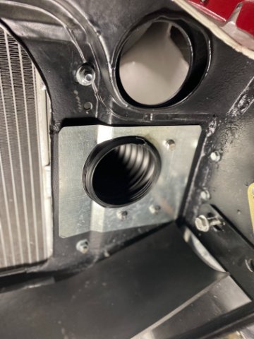
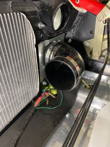
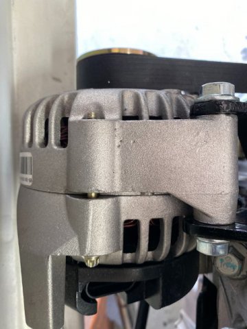
Engine Compartment Modifications- I forgot to post the Alternator that I utilized-NAPA #272-4717 104 AMP Alternator( cost $130). I originally tried to install a 140AMP GM one but it was way too large to fit in the bottom driver side of the motor. I think 104 AMP is sufficient unless I install an Electric Power Steering Unit. The NAPA Alternator has a Lifetime Warranty and 104 AMP is widely available. AIr Intake- My Crate LS3 6.2 Liter motor did not come with a Air Intake Setup so I had to fab one. Spectre Performance had a 4" Stainless Tube ($75), 36" 0fn 4" Flex Tubing($32)and 4" Right Angle Rubber Elbows(($24) for basis of my system. I didn't want my Air Inlet to breathe Hot Engine Compartment Air so I fab the system to get Cold Air from just behind the grille. Had to enlarge the hole in the Core Support to accomplish this. Also, had to "Tap " the Wheel Housing to get about 3/4" clearance for the Duct Hose. Used Shears to Trim the Sheet Metal Plate for the Duct Hose. Inside view of the Duct Opening Using Band Saw to cut 4" Stainless Straight Tube.. Trial Fitting of the Flexible Duct Tubing. I created a Steel Metal Duct Plate on the Core Support to hold Duct Hose and Air Filter. Pic of Additional Right Angle Elbow on outside of Core Support to mount Air Filter. I have not decided on which Air Filter to use yet. Inside view of Air Inlet System Next-Holley Terminator X System installation
-
Heavy Duty frame rails and connectors
toolman replied to toolman's topic in Gen III & IV Chevy V8Z Tech Board
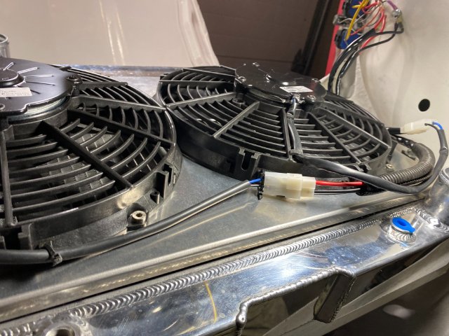
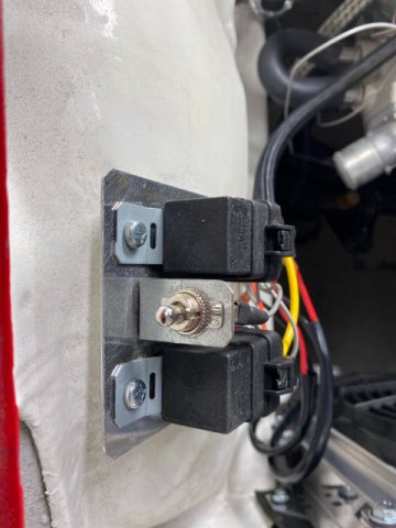
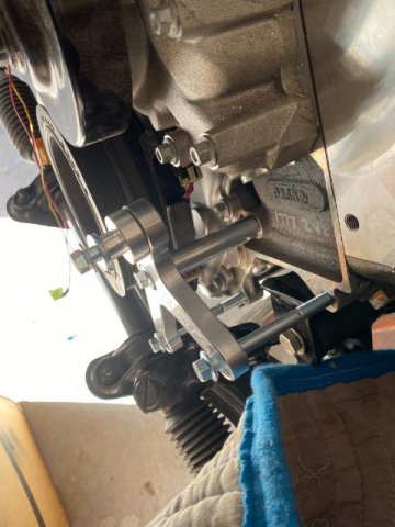
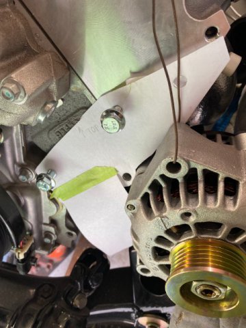
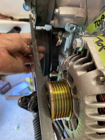
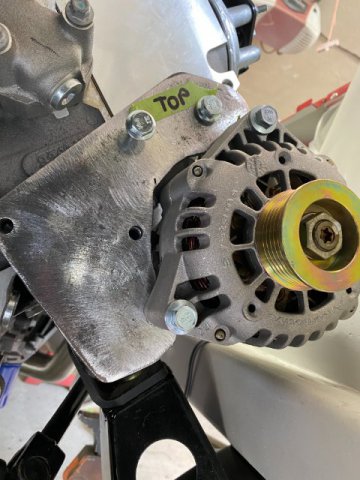
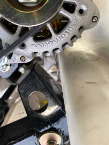
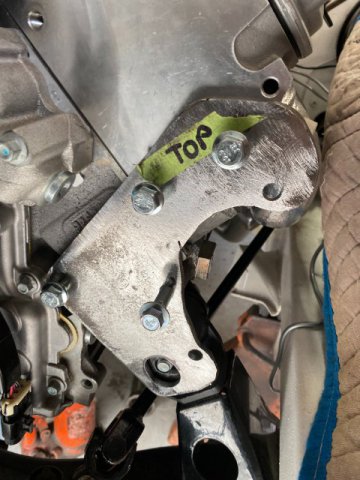
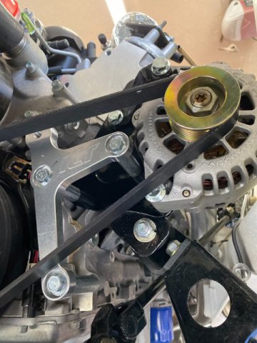
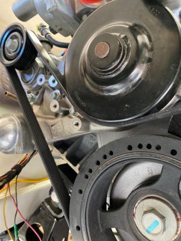
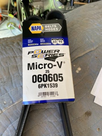
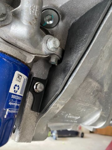
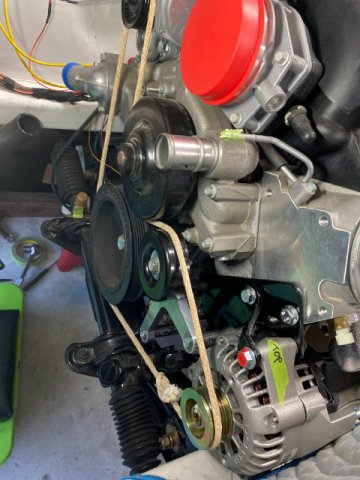
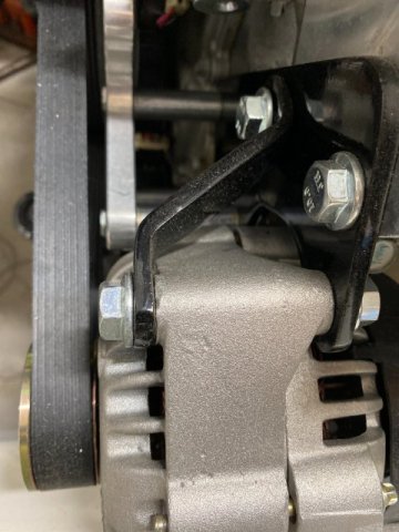
12vt Cooling Fans To go with the Champion Radiator, Two Spal 12vt. Electric Fans and Shroud were installed. The fans provide 1500 CFM of Air Flow but draw 27 maximum amperage. The Two Individual 30 Amp Relay are triggered by a 185 Degree Thermo Switch in the engine block. Spal Dual Fans with Shroud-Bottom View Dual 30 AMP Relays triggered a 185 Degree Thermo Swuitch. I also added an Emergency Bypass Switch to turn on the Relays in case of Switch Failure. Everything was mounted on the Right Side Wheel Well Housing. Alternator Mounting and Belt Arrangement- Originally ordered, a ICT Billet LS Motor Alternator Bracket from Amazon for $40. Unfortunately because my custom made Motor Mounts were located too far forward and the ICT Alternator Mount would not work. So I had to fabricate my own alternator bracket. ITC Billet Mount on my LS3 motor. As usual, I created a Paper Template for the Alternator Mount. Punching Alternator Mounting Holes in Template. Trial Fitting Paper Template Note-Alternator hanging in place with Tie Wire for positioning. Doing Drive Belt Pulley Alignment for Alternator to determine Spacer Size between bracket and block. Using rope to check Drive Belt Arrangement. Created the Mount out of 1/4 Plate Steel using the Template. Note- Plate is oversized so modifications can easily be made later. Checking Alternator Space Clearances Back of Alternator Determining Lower Mounting Bolt Length More Test Fitting Added an additional Upper Alternator to provide additional strength. This additional bracket creates a total of Three Solid Alternator Mounts. Finalizing the Fit Note-I left the ICT Billet Mount possibly use it to mount to a Idler Pulley in case I add Power Steering Pump. later. Used a 2017 Corvette Tensioner to handle Drive Belt Tension. The Final Version of the Alternator Mount Top view of Alternator Bracket Rrear View of Alternator A Dress Maker Cloth Tape Measure was wrapped around the pulleys to determine the Drive Belt Outside Dimension. Ii only took a couple of Drive Belts before I found the correct one. This one fit perfectly. Bell Housing Filler Pieces from AC Delco. Left AC Delco Bell Housing Filler Next-Engine Compartment Wiring
-
5 Star Rising, By your description of different gaps on your Core Support and your Hood Height problems, you might have Twisted Core Support. To verify that conclusion, you must make measurements of your front end. Place your car on a flat hard surface. Make your wheels in straight ahead direction. Take measurements in inches or millimeters. First, always measure from factory bolt holes vertically to the ground . Start at the 10mm bolt attached to the front inside of the Ringt and Left Headlight housings. Since this is the furthest bolt that is attached to the Front Core Support, any body damage will show up as significant differances in your Right and Left Ground Height measurements. If the damage is not too bad , it still can repaired but probably need a body shop to do the work. Please use measurements(in inches or millimeters) to describe your problems. This procedure will aid in determining how to fix your problem. Tool Man
.JPG.f02e294dd5d010b89132322dc4e29078.JPG)


.JPG.77ea333aa560e3170e6e0b5b21ef2675.JPG)


.JPG.9290b46604557d43cbae0ec7473c61a8.JPG)
.JPG.327a5acdd0fc5bd8a772a95b4e089426.JPG)
.JPG.c1a815afc8a3d8173c6f440fd19a06ff.JPG)
.JPG.dbc053df350cae83ffe482a586bf54dc.JPG)
.JPG.7fec26277a49f691b433bb8891a4edad.JPG)


.JPG.a7aa8071550d11c6d746c81a78b84e60.JPG)


.JPG.86ec74376c700192db938841f828250a.JPG)
.JPG.4e69c45153c2a68f2f1247183e68a661.JPG)
.JPG.f86668ee5fa104dca02a3592257fa1ac.JPG)