toolman
-
Posts
615 -
Joined
-
Last visited
-
Days Won
25
Content Type
Profiles
Forums
Blogs
Events
Gallery
Downloads
Store
Everything posted by toolman
-
Heavy Duty frame rails and connectors
toolman replied to toolman's topic in Gen III & IV Chevy V8Z Tech Board
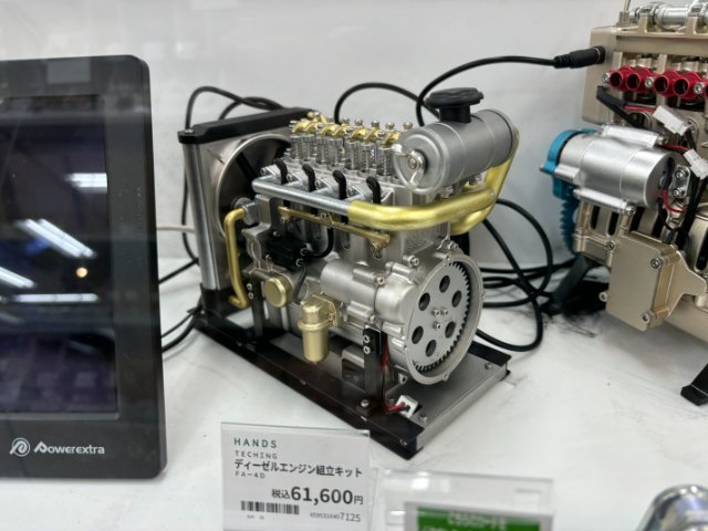
I manage to find two pics that show Model Displays of Scale Motors at AutoBacs Store. Note -the prices of these motors are shown in Japanese Yen. To convert the price into US Dollars- just divide the Yen Amount by 150. The 150 is the Current exchange rate in Japan. One US Dollar is worth 150 Japanese Yen. These Motors have actual cranking movement driven by a small electric motor. I finally found the K Van pic.
-
Heavy Duty frame rails and connectors
toolman replied to toolman's topic in Gen III & IV Chevy V8Z Tech Board
Before I start I wish apologize for not having photos of my JDM Tour in Tokyo. I had about 20 pics to show but they got erased while correcting and lost all of them. Anyway while in Tokyo, I found a 5 hour Night Tour covering various Car Related Places to see. I chose the Shared Group Tour (about 6 to 8 people in a large Toyota van) and because it was a night tour, it didn't interfere my daylight plans. The cost of this particulate tour e $250 per person. It started at 4PM and ended about 9PM depending on traffic. Pickup Up point in my case was Toer Records in Shibuya. It was 300 yard walk from the Shibuya Train Station. At the end of the tour, you are dropped off near your hotel in Tokyo area. The First Stop was the Liberty Walk Store which is tiny 2store in a back alley on Tokyo. It was mostly Promotional Type of Store with t-shirts, hat, key chains,etc. Second Stop-AUTOBACS is a two building which houses a Parts Store (similar to our O'Reileys) on the Second Floor. The Top Floor held high end Racing parts(like Nismo, HKS,etc). Foreigners with Passports can get 10% discount off purchases. Their Book Section had car magazines, books,photo ablums,etc) ica 1/64 cars and all types of trucks and heavy equipment were on display... to purchase. Even had a STARBUCKS CoffeeShop. The Ground Floor, there was a Garage that could handle regular car maintenance or installation of even Turbo setup. Last Stop was the Daikoku Parking Area. This large parking is located in Yokohama Harbor. This parking area is next to where the Japanese Cars(Nissann Toyota,etc) are exported to US, Southeast Asia,etc. There was about 200 cars on the Friday Night that I went. Most of the cars there were the typical Street Racer types. Some JDM cars had UnderCar Lighting systems. A few cars had Full Body Wraps(Cartoon Girls Designs were popular). Majority of the cars were mostly on the quiet side probably because Toyko Strict Noise Regulations. There was one vehicle that caught my eye-it was White K Truck with an Extended Cab and Flat Bed. It had a Dual Floating Rear Axles( total of 6Tires and wheels). The rear axles move individually of each other. Unfortunately, the vehicle didn't stop and kept moving thu the parking area. People said the best night for car viewing was Sunday Night but I was leaving Monday morning, maybe next time. I would still recommend this Tour for Car Lovers to learn Japan Car Culture and see some unique vehicles. -
Heavy Duty frame rails and connectors
toolman replied to toolman's topic in Gen III & IV Chevy V8Z Tech Board
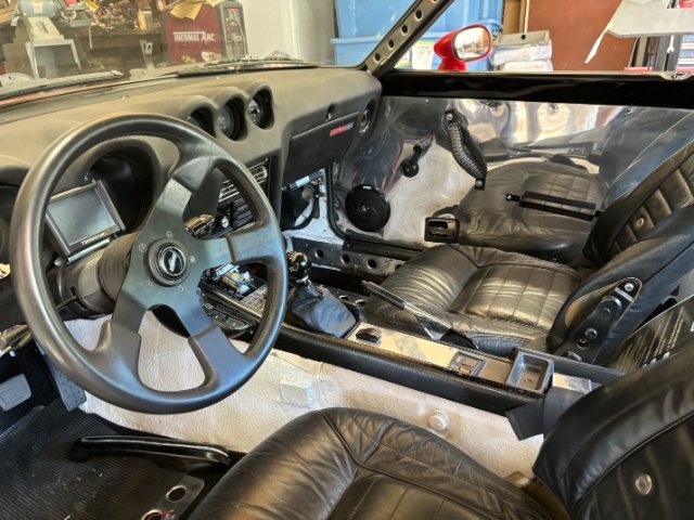
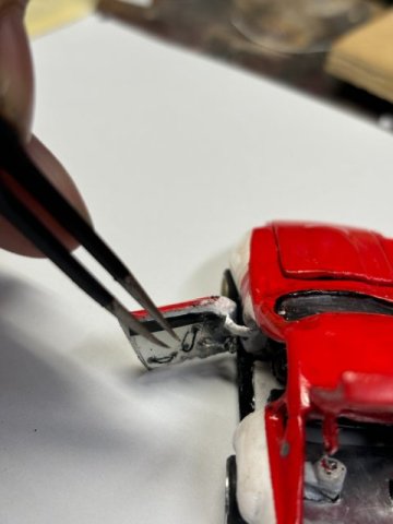
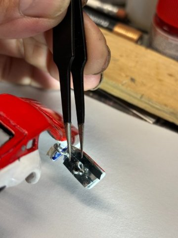
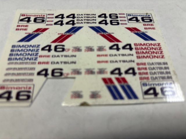
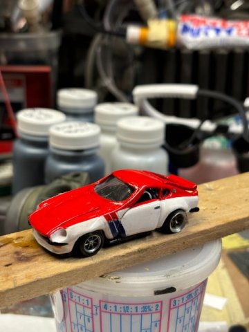
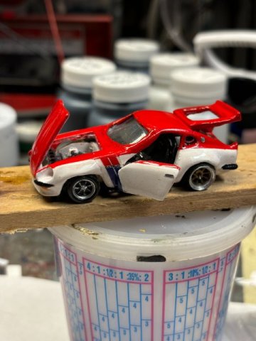
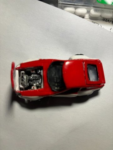
Detailing the Interior- Installing the Battery into the Engine Compartment. LS3 Motor installed in car- Roll Bar installed and Chrome Rear Hatch Floor. using Tweezers to put in Door Handles and Window Crank on Left Door. Installing Door Pull on Door Panel on Right Door, Ebay supplied the 240z Morton Race 240z Decal Sheet for $10. After the Red and Blue Stripes with "DATSUN" were put on the cat then Clear was sprayed on. The Finished Car Pics- Top View 240z with Open Doors, Hood and Rear Hatch. Next- Ford 8.8 Differential Conversion
-
Heavy Duty frame rails and connectors
toolman replied to toolman's topic in Gen III & IV Chevy V8Z Tech Board
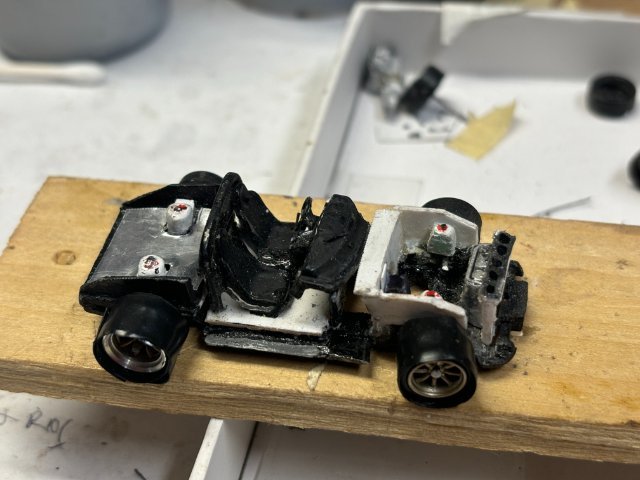
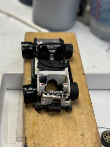
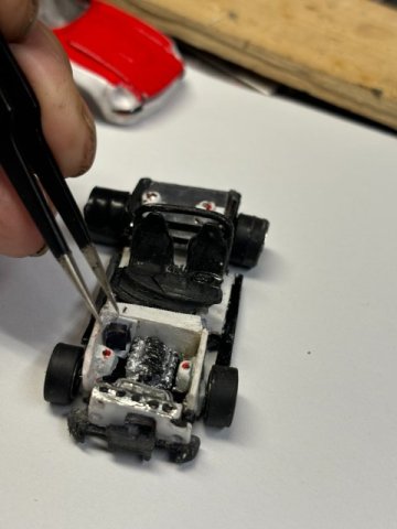
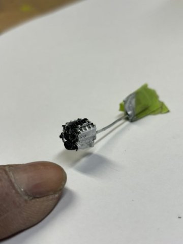
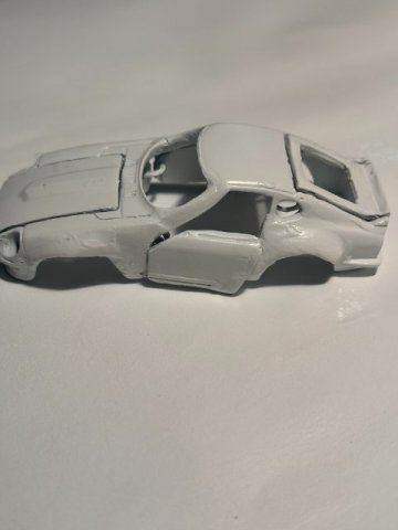
Painting the 1/64 scale 240Z- I masked off the Bottom of the car for the Bright Red Top Coat. I had to mask off the sections that would end up White. Next, After the Red Top Coar was sprayed and dried overnight, the masking paper was carefully removed. Now, the Red Section must masked off for the painting of the White Lower Section to be painted. At this point, the car should resemble something like this. While allowing the White Paint to dry 24Hours, I decided to work on the Engine Compartment. I had to fabricate the Aluminum Radiator. It made from Scrape Flat Plastic Sheet. I glued a tiny piece of fabric to give the radiator finned look. Then, I brushed it with Chrome Silver. Yes, the Radiator is Tiny. That small size of parts gave me the biggest headaches as parts were so easy to lose. Engine Compartment was also constructed with Flat Plastic Sheets. Note-Battery on the Left Side of the Firewall. The Radiator was mounted on the Fabricated Core Support which has the Holes on both sides of the Radiator. The Strut Tops were painted Red Metallic. Tweezers had to be used to installing all of the components (like brake master cylinder,etc) Brake Master Cylinder Finally, the LS3 motor (got from Ebay). but nobody made T-56 6speed transmission. So I craved on out of Balsa Wood. LS3 Motor detailed painted with Gloss Black on most engine components. LS3 AND T-56 Transmission installed in engine bay. Next-Detailing the Interior
-
Heavy Duty frame rails and connectors
toolman replied to toolman's topic in Gen III & IV Chevy V8Z Tech Board
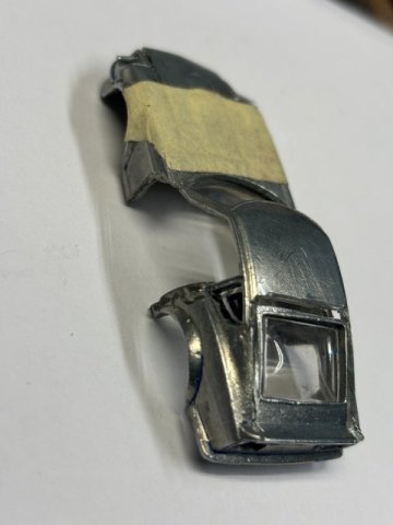
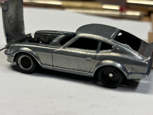
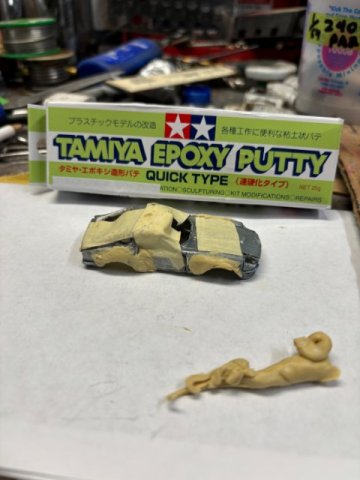
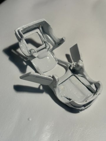
Creating Opening Doors and Hood- First thing in creating Opening Doors is cutting the Doors from the Die Cast Body. A Hobby Saw makes this easier if there curves involved besides just straight cuts, Notice the Shape of the Wire( paper clip can be used). The Straight End will attached to the inside of the Door Panel and Cruve Side willbe attached to the inside of the Fender( a flat side of plastic will drilled for the Hinge Pin to be inserted). This will the Hinge Pivot Point. The Body with Door Opening The Door Hinge installed first on the Fender The Horizontal Side of Hinge can be glued to the inside of the Door Panel. You can use masking tape to test fit the door before gluing this end of the Hinge on the inside of the Door Panel. Test Fit the Door by opening and closing the door and checking its alignment. You can carefully bend the Hinge till good alignment is achieved. The Hood Hinge is easily made by drilling a .027 hole in the headlight buckets on both sides of the Hood. Then a straight .025 wire is inserted between the Two Headlight Buckets. A Drop of Instant Glue can be used to fasten the Hood to this Pin. Test Fit the Hood and Bend the Wire carefully to get the Hood Aligned properly. The Car should resemble somewhat like this-Opening Hood and Doors with Hatch Open. Body Work-Rocket Bunny Flares Using Tamiya Epoxy Putty(available on Amazon) I formed the Putty into a Rough Shape of the Rocket Bunny Flares. Using a Sharp Knife, i sharped the Putty into Final Bodywork. Then Hand sanding with # 80 Grit Sandpaper. Then going to# 400 Grit to get the surface smooth. Priming the Car- Now, the Whole Car must be Primed inside and outside with Primer Filler. This will cover any left over scratches and small imperfections. Inside of Car Primered Outside of Body Primered. Next-Sanding and Painting
-
Heavy Duty frame rails and connectors
toolman replied to toolman's topic in Gen III & IV Chevy V8Z Tech Board
Armorer, After much thought. I decided to use Incredible Extreme Muscle Car Garage one. He uses the Ford Super Duty 8.8 Differential which is much Stronger than the older Ford Explorer one. The kit uses Ford Mustang Suspension Parts( Hubs, bearings,etc) which readily available. His Box Structure for the differential makes the whole unit very strong. Watch his suspension work on that 8 second Green Z confirms this fact. Late Model Mustang used softer bushings in their rear suspensions. This caused many Mustang crashes because of being excessively soft. Drag Racers ended up in replacing all of the Rear Suspension Bushings in their cars. The Super Duty 8.8 differentials also has 34 splines vs 32 splines in Explorer ones. More splines gives additional torque strength. Broken axles can make the vehicle veer 90 degrees and cause a crash as there is no way to correct in time. Another reason to use a Super Duty 8.8 differential is it has a Torsion Limited Slip. Only a few Explorer 8.8 differential came with Limited Slip. I hope this info helps you make your decision. -
Heavy Duty frame rails and connectors
toolman replied to toolman's topic in Gen III & IV Chevy V8Z Tech Board
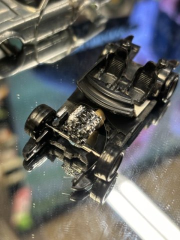
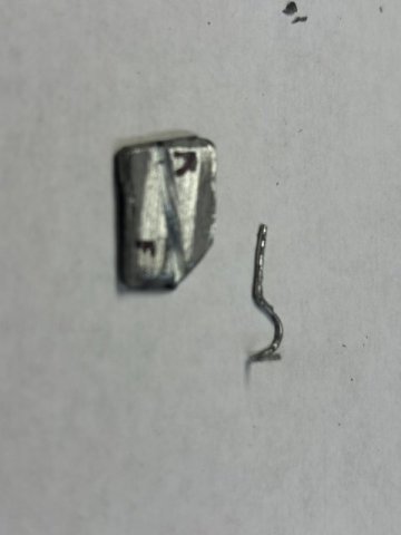
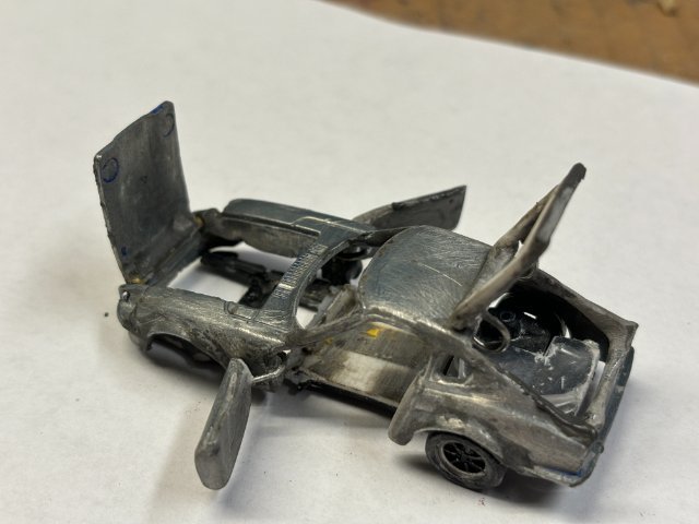
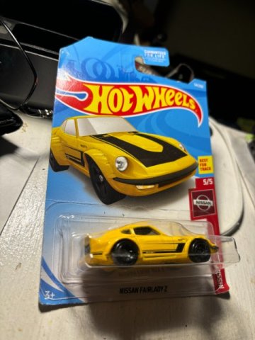
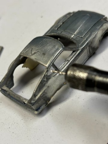
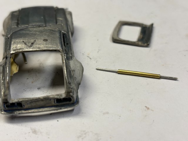
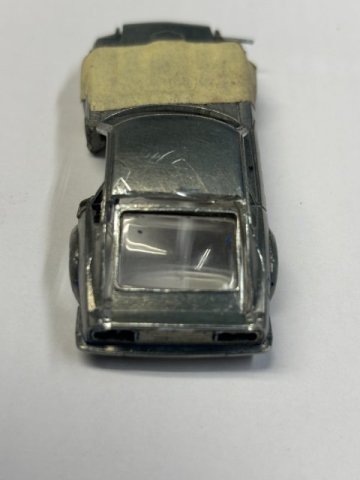
CREATING A HOT WHEELS 1/64 REPLICA OF MY 240Z While awaiting my Ford 8.8 Differential Conversion Kit, I decided to create a Hot Wheels Replica of my 240Z. Sure I made a lot of 1/25 scale model cars when I was a teenager. But I never made a 1/64 scale car. Maybe some other 240z owners might be interested in process. First, I started with a Hot Wheels version of a basic 71 Datsun 240Z. This car must opened up by drilling out the two Rivets that secure the body to the chassis. The body is stripped of all windows and prepared for paint stripping. Regular Automotive Paint Stripper can be used. This process should take only a half hour or so. The body shell is sanded with #400 sandpaper to provide smooth surface and eliminate any small burrs. Now, the most difficult portion of this job is the creation of opening doors, hood and hatch of this 240Z. As this car is a sports car, cutting the body must be performed carefully. I have used a regular hack saw blade to do the cutting. I would recommend to purchased a Hobby Saw(from Amazon). The Saw comes with blades small as 2mm and is much easier to handle in tight cuts. This pic shows the cutting of the Rear Hatch with a modified Hack Saw Blade. This pic shows a Pin Vise used to drill a .030 hole for the Hatch Hinge Pin. The Hatch Pin and Hatch Hinge shown. The Working Rear Hatch. Next time, Creating Opening Doors.
-
I considered installing a late model Camaro Differential assembly into my 240Z. Mounting the Camaro would not be the biggest problem to overcome. Creating the Rear axle Bearing Housing connecting the Lower Rear Control Arm and the Strut Cartridge would be the Biggest Problem. It will needed to made of 3/8" Flat Mild Steel or Greater. A Machinist Lathe also be necessary to create the Bearing Housing. The Dimensions would have figured out by mostly trial and error. One, that Housing was made then you have get New CV Axles for both sides custom made. The Differential Mount would have to fit below the rear Frame Crossmember. The Differential Front Mount must allow for Driveshaft Angle. There are many factors that must considered before trying to installing any nonstock differential especially with Independent Rear Suspension Vehicle. My advice would be studied different Rear Differentials conversions on the market already and learn from them.
-
A Excellent Video on A Complete Body Restoration of a 240Z car
toolman replied to toolman's topic in Body Kits & Paint
Finally, Preparing and Painting the car. This video was very good to give you an idea of what a complete restoration (body work and painting) would look like. In this case, the vehicle was already in very good shape with only minor body work to do. The cost of this particular job would vary reatly depending on local labor rates, material costs,etc, Also, remember this vehicle was in excellent body condition, most Zs would seldom be in this good condition. So I would guess this job cost would range from $15,000 to$25,000 if done in the States. Maybe if you have a similar body work and paint restoration done, you post how much you paid and what region it was done. -
Heavy Duty frame rails and connectors
toolman replied to toolman's topic in Gen III & IV Chevy V8Z Tech Board
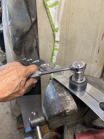
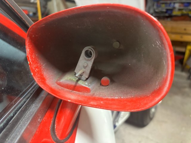
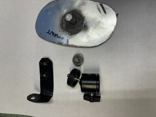
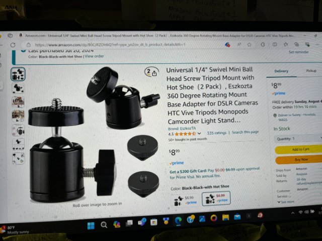
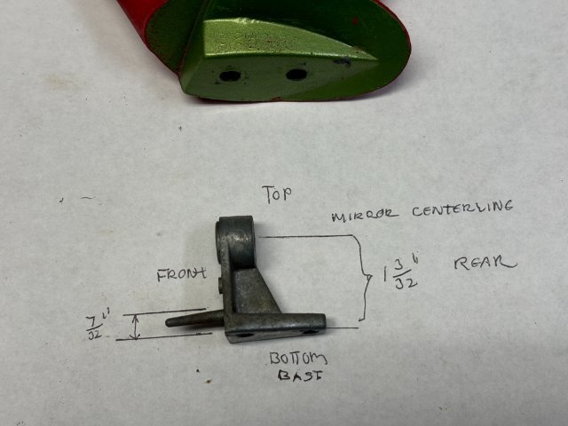
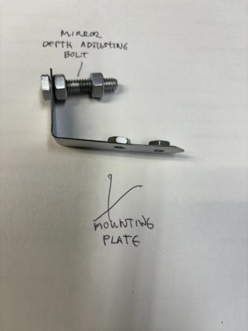
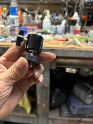
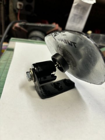
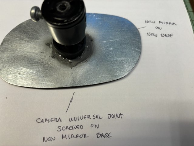
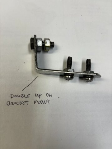
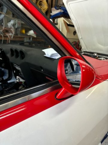
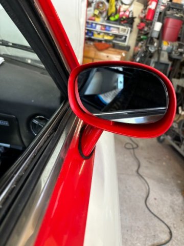
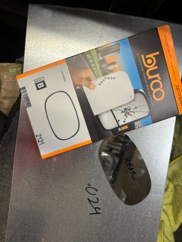
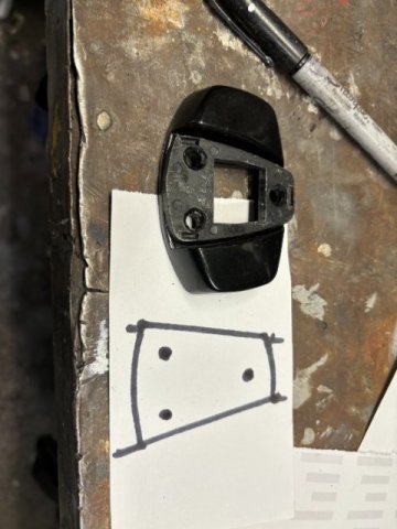
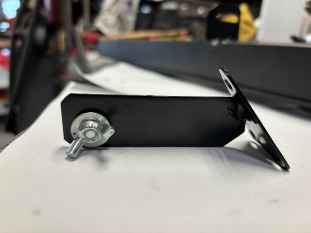
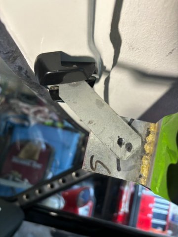
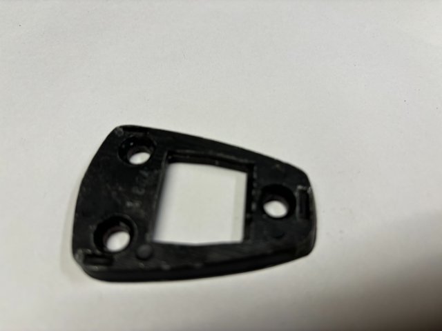
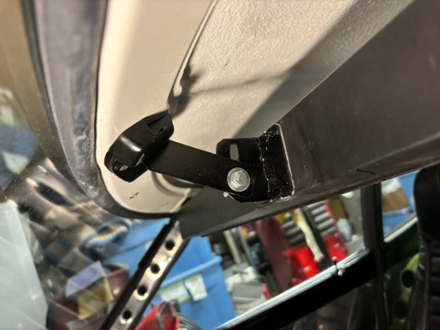
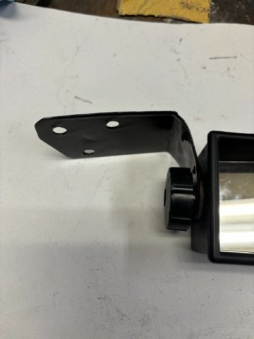
Replacing Passenger Side Mirror- This topic is slightly off topic as my side mirrors are from &2 Camaro. But figured, some people might be interested in the process anyway. My Passenger Side Mirror fell off one night after I hit a Pot Hole. Not just the mirror itself but including the plastic mounting plate behind it. So I could not just purchase the Mirror itself. I would have to fabricate a swivel mount for the mirror and be small enough to fit inside the mirror housing. My Camaro Mirror missing its mirror First, Ebay had the Replacement Mirror for 70-78 Camaro for $18.29-BurcoMirror Glass #2121. Only thing wrong was the mirror didn't come with a Backing Plate. So I traced and made a Template out of cardboard. I traced the Template over a piece of 16 gauge sheet metal. Shears was utilized to cut out Backing Plate. A 1/4" x 1" bolt was tacked to the rear of the Mirror Mounting Plate. New Mirror attached to New Baking Plate Below that is the new Created Mount and new Swivel Mount The New Swivel Mount was located on Ebay. It was a Universal Swivel Mount for small camera on tripods. Two Mounts were only$8.00. The main features were the mount was threaded 1/4" male on one end and 1/4" female threaded on the other end. Also, the Swivel Tension and Mirror Height could both adjustable. This feature was especially important in a custom installation. Note-Dimensions are on the left side of picture Original mirror Mount Dimensions New Mirror Mount for Swivel Mirror Plate New Swivel Mount Swivel Mount attached to New Mirror Plate Note - the Mirror Depth can adjusted by adding or deleting washers between mount and mirror Note-Phillips Screw on Swivel Mount adjusts tension on Swivel. This pic shows the Double Plating on Mount Base to prevent Mirror Vibration. View of Mirror Assembled and Mounted Closeup View of Completed Mirror
-
Heavy Duty frame rails and connectors
toolman replied to toolman's topic in Gen III & IV Chevy V8Z Tech Board
Sorry for the lack of photos in the previous post on Wrapping Door Handles. I had trouble loading pics with the new IPhone Update. However, I now installed photos that went along with that posting. -
Heavy Duty frame rails and connectors
toolman replied to toolman's topic in Gen III & IV Chevy V8Z Tech Board
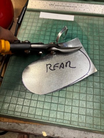
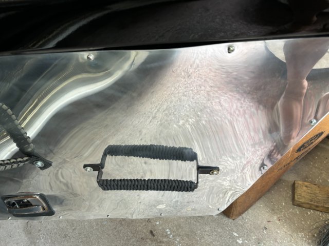
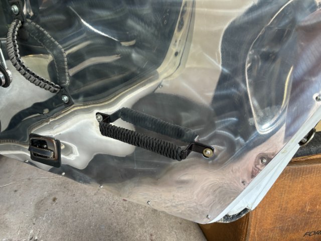
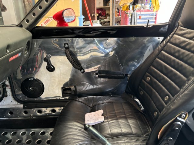
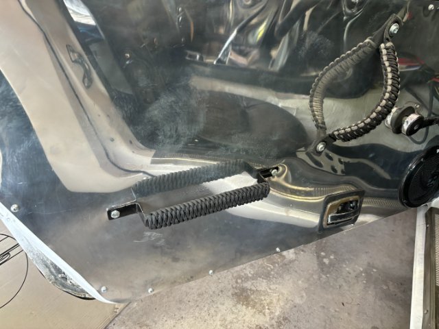
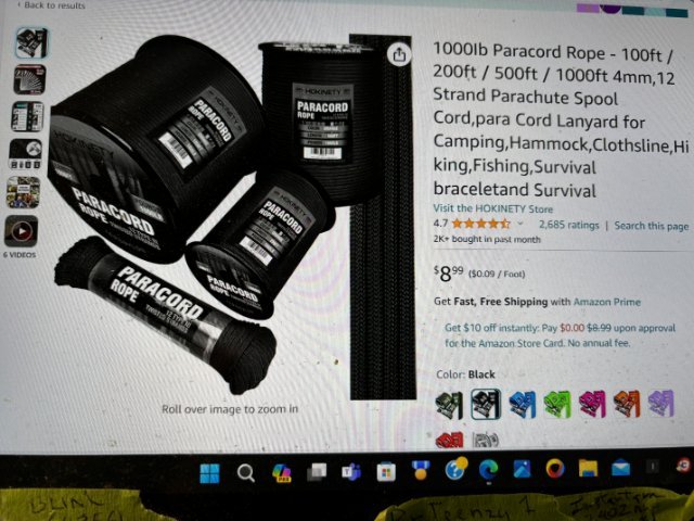
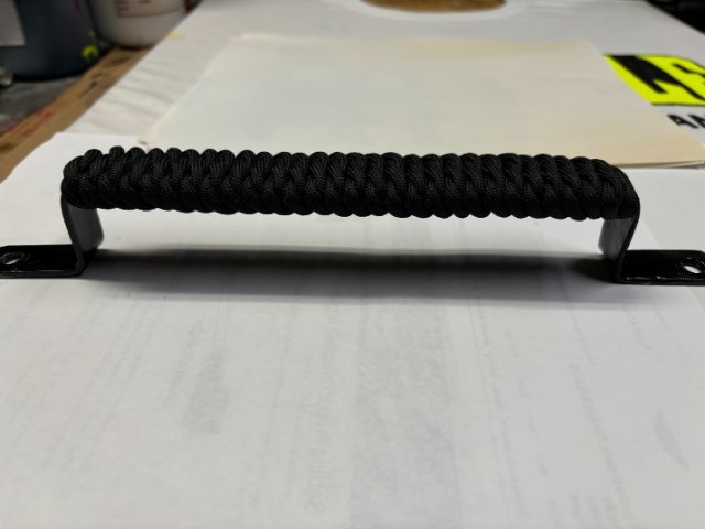
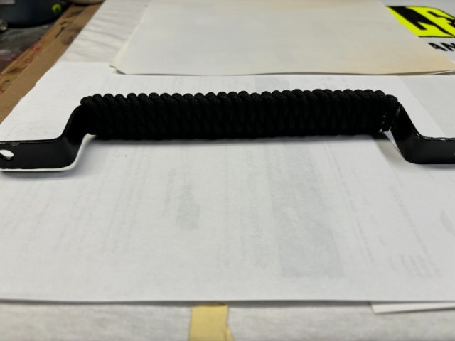
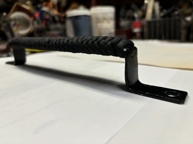
Wrapping Door Handles with Parachute Cord- When I installed Aluminum Sheets to replace the Factory Masonite Panel, the Original OEM Door Pull Handles had to replaced. The Diagonal Handles were replaced with Aftermarket off Road Jeep Parachute Cord ones. However, the Horizontal Door Pull were fabricated with 3/4" x 1/8" Mild Steel Strap. It performed ok but did not have any padding so they lacked the correct feeling. I considered using Large Heat Shrink Tubing to cover the Pull Handles but decided on Wrapping the Handles with Parachute Cord. It was only about $10 for 50 feet of Black Paracord on Amazon so figured to give it a try. For this project, I used about 15feet of Black Paracord to perform this wrap per handle. Door Handle finished wrapping-side view Bottom view of Wrapped Door Handle Side View of Wrapped Handle Wrapped handle on Right Door Outside View of Right Door Handle As this was the first time that attempted Paracord wrapping, it took me about an hour to do the wrapping. I kept checking each knot to make sure that I did it right. I used JB Weld Fast Drying Epoxy after the First Knot and at the end of the wrap, I fold over the cord and applied epoxy to glue the cord from unraveling. Overall View of Right Door Vjew of Wrapped Left Door Handle
-
A Excellent Video on A Complete Body Restoration of a 240Z car
toolman replied to toolman's topic in Body Kits & Paint
This is Part 3 and 4 of the 240Zrestoration. These videos demonstrates pretty advanced body working skills and more specialized repair equipment but figured people would still enjoy watching it. Part 3 Advanced Bodywork Preparation for Primer and Paint An Alternate Method of Sand Blasting the 240Z body is to Spot Weld Four 4" Metal Casters to the Frame Rails. High Body Mounts would be hard to move around especially on rough and uneven surfaces. Especially transporting the 240z ona Flar Bed Truck to the Sandblaster. Most Sand Blasting Businesses have a Folk Lift to raise the vehicle to perform the sand blasting of the bottom of the vehicle. Having the vehicle couple high off the ground would make sand blasting of the under the dash and the bottom of the roof sections. If you did not have a rotisserie, the casters would allow the vehicle to move around the work area easily. Because of space limitations, I chose to build a Wooden Tile Rotisserie to work on the floor pans and rocker panels. The Rotisserie also allow work on under carriage and undercoating. Upon completion of painting, the rotisserie was taken apart and the lumber was used for other projects.
-
Heavy Duty frame rails and connectors
toolman replied to toolman's topic in Gen III & IV Chevy V8Z Tech Board
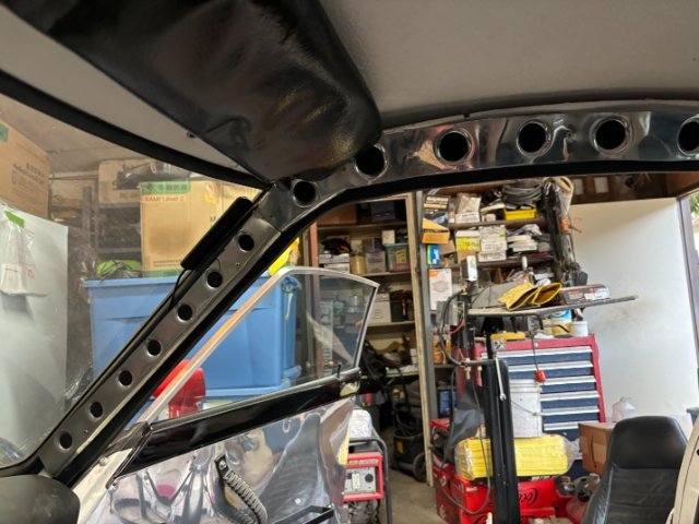
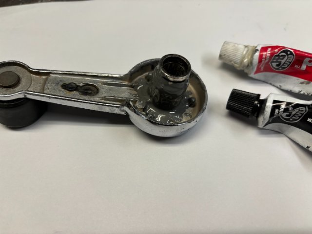
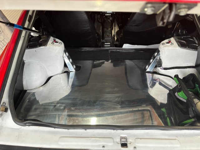
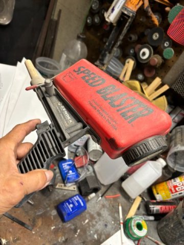
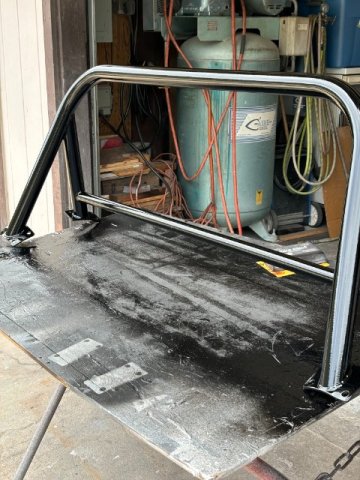
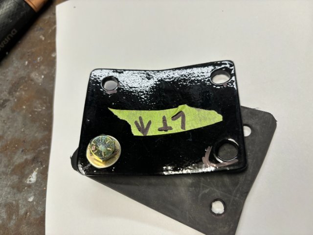
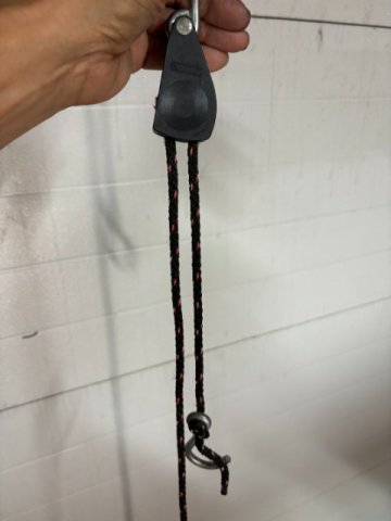
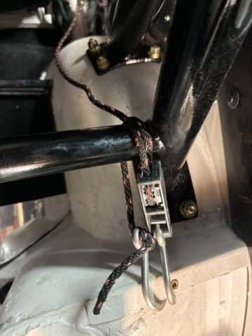
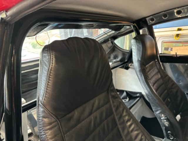
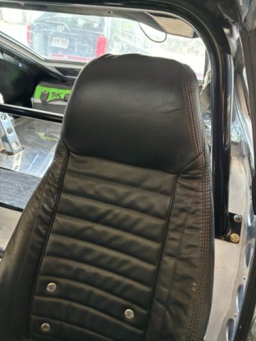
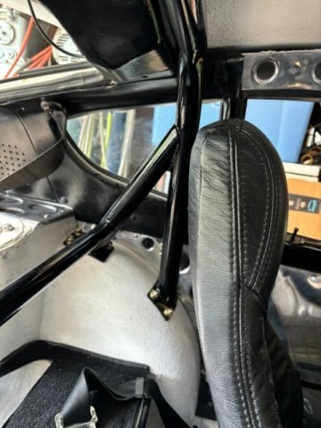
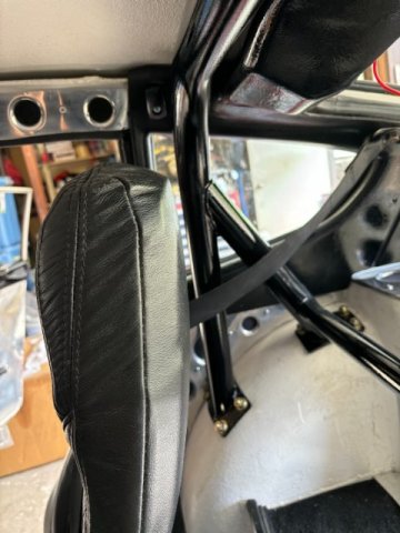
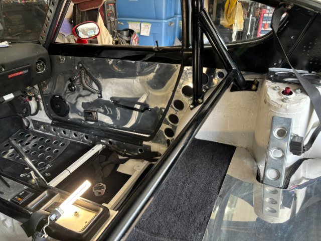
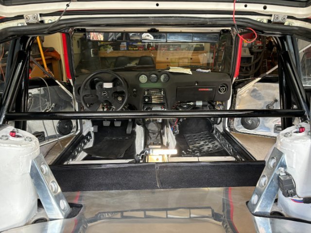
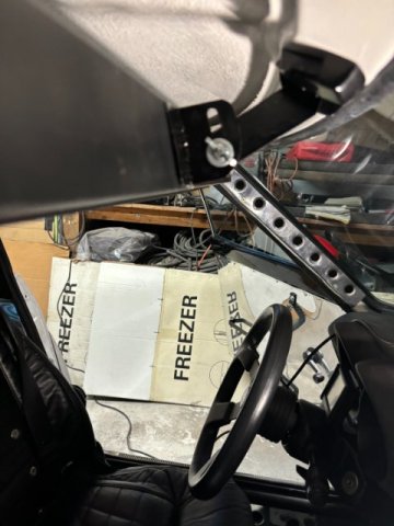
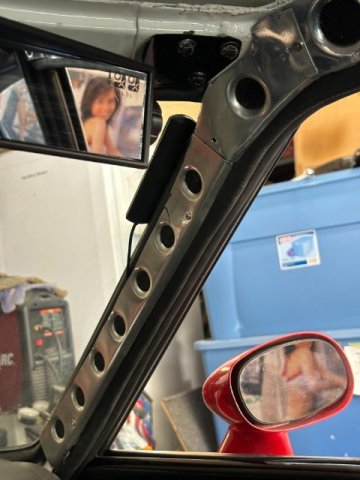
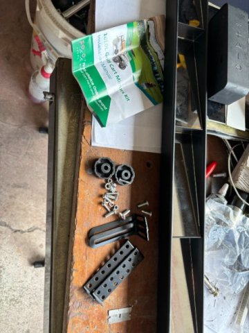
ROLL BAR INSTALLATION- While I was at a local 240z gathering, I found one Z owner who was selling a AutoPower style 240z Roll Bar for $150. It was missing the Four Mounting Pads and mounting bolts. The Roll Bar was first stripped of existing old flat paint using an Orbital Sander. I used 80 grit sandpaper for this process. Next, a small portable Speed Blaster air powered sand blaster. Similar sand blasters are sold at Harbor Freight and on Amazon for about $30. These sand blasters do a great job for rust and paint removal especially in tight areas. After paint removal, the Roll Bar was primered and preparred for color. As the Bottom Mounting Pads were missing , substitute plates had to fabricated from 1/4" Steel Plate. A 5lb Sledge Hammer and 12 ton Press were utilized to form the matching shape of the Roll Bar pads. !/4" thick Rubber Mat was used to go between Upper and Lower Mounting Plates to seal water from coming in the wheel wells. Cadmium Coated 3/4" NC x 1 1/2" bolts, Flat Washers and Lock Washers provided the mounting hardware. To hold the Roll Bar in position while marking the mounting blots hole with a Felt Pen, !/4" Rope Ratchets were used. They are sold at Home depot for about $20 each. They are super useful (holding up driveshafts, calipers, keep hoses out of your way,etc). One of the Rope Ratchet hook was attached the Rear Strut Tower Support. The other hook was wrapped around the Roll Bar Tubing. Adjustment is made by slowly tightening the Rope Ratchet to get the correct height. Shifting the Roll Bar side to side is done to obtain similar spacing on both sides of the mounting pads to the interior walls. Once the Correct height and Side Clearance is established, a Felt Pen is used to mark all the mounting holes. Then a Center Punch is used to prevent drill bit to drifting due the curved surface of the wheel housing. A slightly larger than 3/8" drill bit is utilized to drill all of the mounting holes. When assembling the Roll Bar on, One 3/8" bolt for each side is inserted thread first and tightened slightly to the Bar in place while installing the other bolts upward from the inside side of the wheel housing. Left Wheel Housing with Lower Mounts installed- Looking Sideways in car -checking Roll Bar Height Looking Forward at Roll Bar Viewing the Right Inside Wheel Well Left Side Looking Back Passenger Seat Looking Backwards View from Rear forward I posted a lot of pics of the Roll Bar installed so people can see the clearance available with this model. Many Custom Roll Bars don't have enough clearance for Tall Drivers. Interior View of Roll Bar without seats installed.
-
Heavy Duty frame rails and connectors
toolman replied to toolman's topic in Gen III & IV Chevy V8Z Tech Board
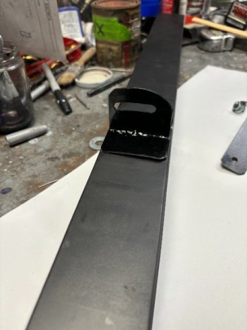
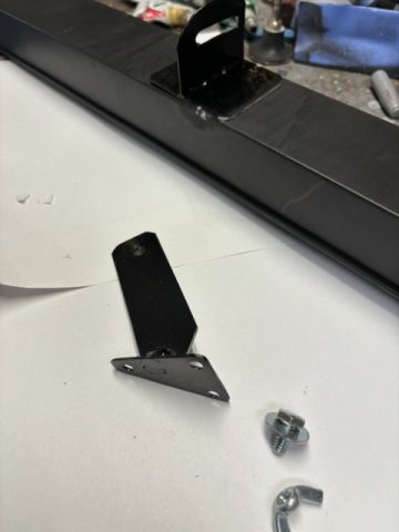
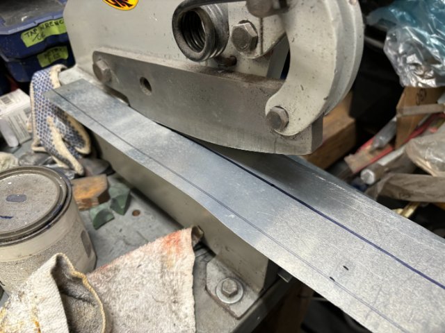
Modifications to the New Rear View Mirror- After driving the car, I found that the new rear view mirror was vibrating making viewing difficult If, however, I would hold the mirror in the center, the viewing improved greatly. The solution was to provide additional support to the mirror. I would use the original rear view mirror mounting screw holes to mount a additional center bracket. First, a Template of original mirror base (consists of three screw holes)was created. The base mount would be constructed from 16 gauge steel plate. Another 3/4" x4" rectangular piece were created to make the Pivot Arm for the mirror. This plate would welded to a base 2" x 4" which would be epoxied to the back of the mirror. Mirror Mount Note- A 1/4" Pivot Hole was first drilled in the top section of this arm. This Pivot Hole will enlarged after the Mounting Bracket and Mirror Bracket are test mounted together. Then, a felt pen is inserted into the 1/4" Pivot Hole and the Mirror is turned to create its "curving path". This path will used to create the slot that allows the mirror to be adjusted when necessary. Drilling many 1/4" close together then hand filing created the arch path. Note-Arch created by Felt Pen Pic shows Arm and mounting base tack welded together for testing only until alignment is completed. Bracket angle will determined with Two small card board 1" strips- one is simulate the bracket arm and the other to stimulate the bracket on the mirror. pic showing !/4" Pivot hardware(1/4 bolt, washer and wing nuts) Assembled Version of Base Mount The Original Mirror Spacer was not used to allow sufficent thread engagement. Completed Modified Rear View Mirror Left Side View Right Side View NEXT-Roll Bar Installation
-
Heavy Duty frame rails and connectors
toolman replied to toolman's topic in Gen III & IV Chevy V8Z Tech Board
Upgrading Interior Rear View Mirror- The Original Factory Interior Rear View Mirror has Blindspots due the Quarter Panel Pillars. So I decided to upgrade it with a Multiple Rear View Mirror. Race Cars use them to see better when passing other cars. Amazon had this one that was for Golf Carts that was 36" long. Usually they had 24" rear view mirrors for cars but I felt the longer the better. Plus , it was only $25 anyway. This is a pic of the Rear View Mirror upon opening package. I decided to.make my own mounting brackets using the original rear view mirror mounting holes. First, Paper Templates were made using existing mounting holes as a guide. Brackets are first created out of aluminum sheet metal making the shape easier. Then, after the basic shape was established, Brackets were made from 16 gauge sheet metal. The 16 gauge sheet provides the stiffness to support the weigh of the Mirror. With the Brackets mounted and tight, their shape was acheived by slowly bending and twisted them to fit the mirror properly. The Tilt Adjusting Knob was installed with a Small Rubber Gasket between the mirror and knob to provide additional tightness. The New Rear View Mirror was installed using the original mounting holes. Close Up View-of Right Side view with the New Mirror The Viewing Test was successful ( the Girl was visible in both Rear View Mirrors).
-
Heavy Duty frame rails and connectors
toolman replied to toolman's topic in Gen III & IV Chevy V8Z Tech Board
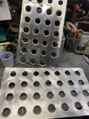
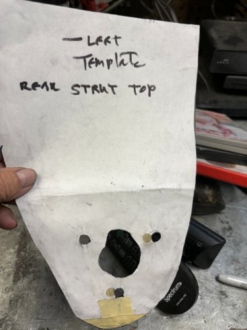
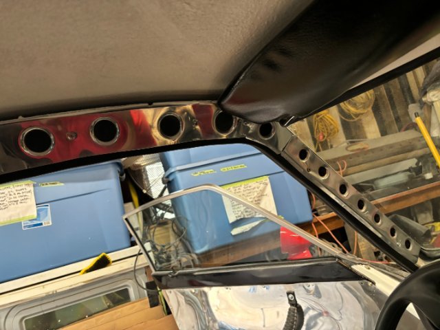
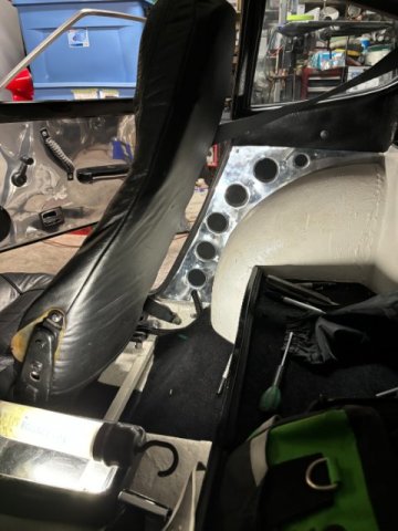
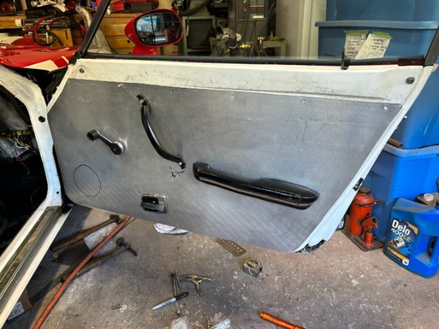
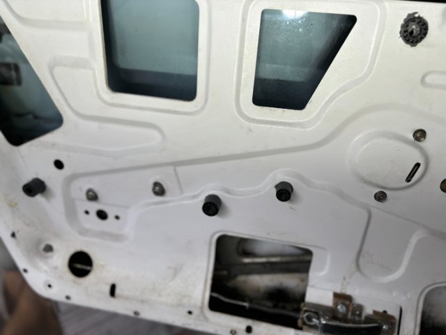
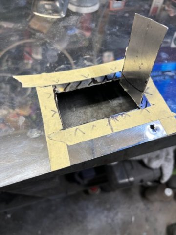
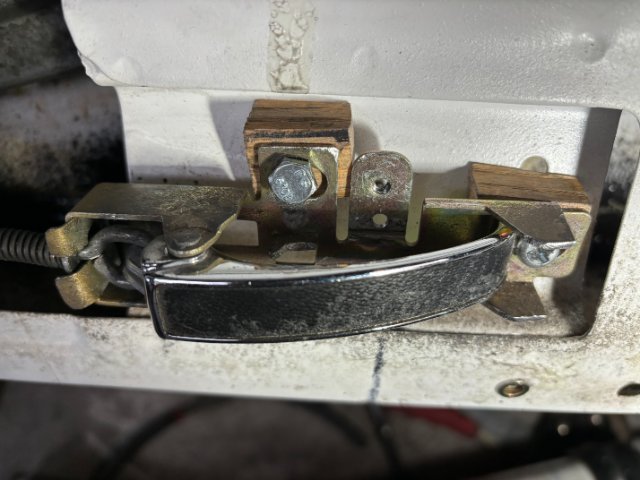
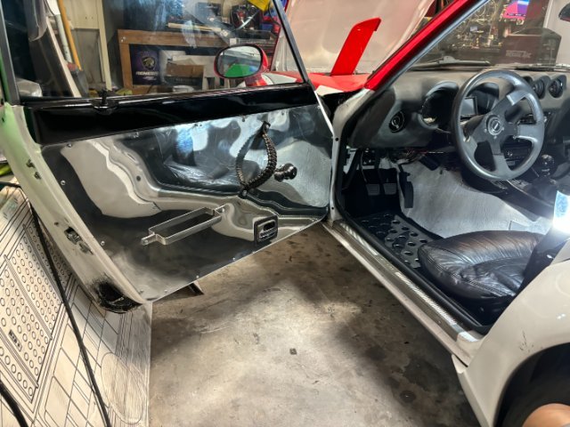
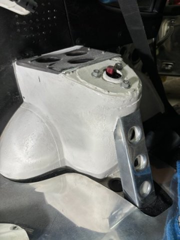
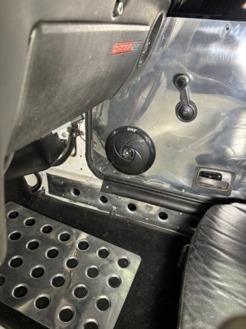
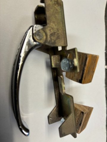
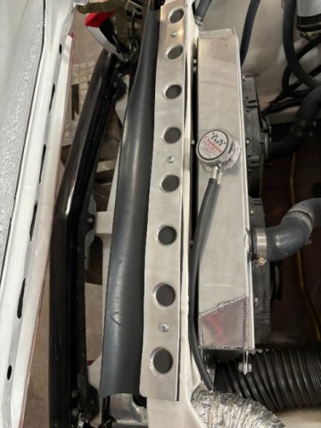
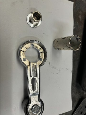
i will discuss my Interior Modifcations created to add to the "Race Car" Imagine of 240Z Restro Mod. Using Dimple Dies - Dimple Dies are used regularly in Race Cars to strengthen and at same time lighten vehicle weight. Dimple Die tools are basically a Male and Female Round Hole Dies. In the center, a Bolt is used to squeeze the sheet metal into a Reinforced Round Hole. Completed Dimple Die Panel To create Upper Strut Tower Covers, A Paper Template was made First. Strut Tower Brace Covers with a Polished Aluminum Rear Deck Plate Rear Hatch Area also Large polished Aluminum Pan was added. Another view of the Hatch Area Interior Mouldings Front Passenger Side Interior Moulding Front Driver Side Aluminum Moulding Lower Interior Rocker Panel Covers Dimple Die Panel installed on Right Rear Quarter Panel Aluminum Door Panels To install Aluminum Door Panels on a 240Z took more work as the interior side of the doors are not flat as most cars are. They were constructed this way because of the confined inteirior area. Trial Fitting of the Non Polished Aluminum Door Panels This Test Determined that Spacers are needed because of the "uneven interior door surface'. A Straight Ruler. It shows that 3/4" spacers are required to attach the Door Pull Handles' Note-Three Black Round Plastic 3" Spacers glued to the Door Skin with JB Weld. The Other Problem is the Window Crank Handles is be extended by about 1/2" longer for clearance to operate. A Extra Window Crank Handle must be use to cut the Spline End off to extend the shaft. A Hole Saw is used to remove the shaft off the crank.. The 1/2"Cutoff Section is attached to the Original Crank Handle with JB Weld Adhesive. This will allowe the Window Crank Handle to "clear" the Door Panel. Also, Other Modification that must be made to the Door Release Mechanism.to function properly. First, the Aluminum Panel must cut out to mount the Door Release Mechanism. A Dremel Tool was used to perform this task. Also, the Door Release Mechanism itself must be"Tilted upright" in it mounting position. This is accomplished by fabricating Triangle shaped wood blocks under the bracket. Oak Blocks was used for its strength ,avaiabllity. and ease to fabricate. Two Longer 6mm x1.0 bolts are necessary due the Wooden Blocks. Door Release Mechanism installed Window Crank Modification Using a Hole Saw, a section of an extra Window Crank was removed. This section was filed down so the core portions would match for sectioning. Window Crank Handle Extension joined using JB Weld With this 1/2" Extension, the Window Crank Handle has enough clearance to operate. Aluminum Door Panel now Completed- Drivers side Door Panel Fastners Used All of the Dimple Die Alumunium Covers were fastened using Rivet Nuts and Small Machine Screws (4MM x o.7 ). The only exception were The Upper Interior Aluminum Covers were fastened with 1/4"log Phillips Screws. Radiator Support TopCover I also added a Aluminum Dimple Plate to hold a 1/4"x 4" wide Rubber Strip which seals the Hood and Radiator Support Area. This Seal directs more air through the radiator. Right now, the Water Temperature runs 193 degrees and up to 200 degrees with AC running. Hatch Interior Cover A Polished Aluminum Flat Panel was attached to the bottom side of the Hatch. It was attached with Plastic fastners. Next Topic-Rust Proofing the Vehicle
-
Silvermine Motorsports -Ford 8.8 Rear End Conversion for 240z
toolman replied to toolman's topic in Drivetrain
Techno Tuning 240z 8.8 conversion kit cost $56850 plus freight is the most complete kit available but also the most expensive. https://technotoytuning.com/nissan/260z/complete-ford-88-rear-end-conversion-z-car Anybody have any comments on this conversion ? -
A Excellent Video on A Complete Body Restoration of a 240Z car
toolman replied to toolman's topic in Body Kits & Paint
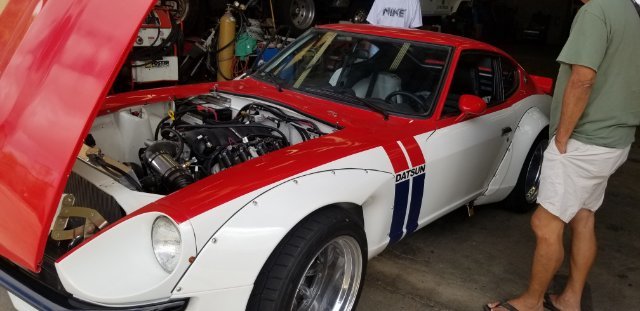
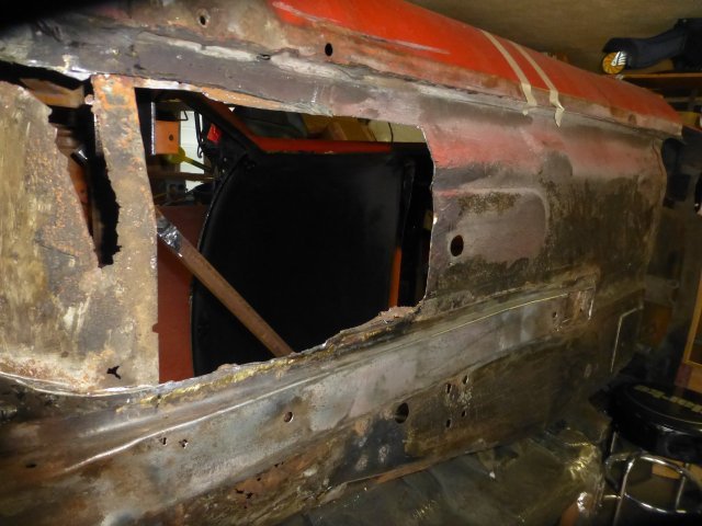
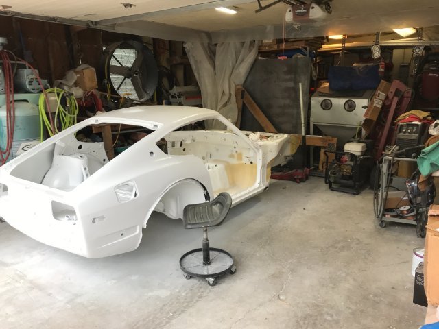
Thanks for all comments about restoring a 240Z. I decided to post these videos because when I started to put my 240Z in car shows, alot of people(young and old) didn't really understand how much work was involved, I spent working on the car for 5 years(working after work, weekends and holidays and about 2 years straight after I retired. i was lucky because My father own a Autoi Body Shop and I have ASE Certified License in Auto Mechanics and Automotive Collision. This experience allowed me to do 99% of the work by myself including painting. Built the whole car in my home 2 car garage. Also, made a Wooden Rostisserie to do the floor pans and some under carriage work. Since a new crate motor LS3 6.2L motor was going into the car, I constructed a 3/16" X 2 1/2"square tubing frame and midframe made of 1" x3" tubing. The main reason for going through all this work was this 240z was my First Car that I ever bought on my own. Everyone wishes they still had their First Car. right? Toolman Before After
-
Heavy Duty frame rails and connectors
toolman replied to toolman's topic in Gen III & IV Chevy V8Z Tech Board
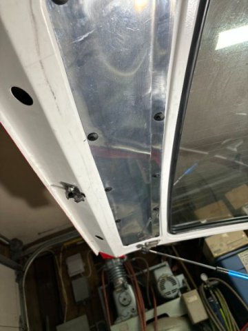
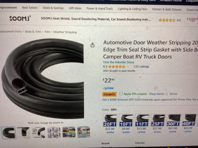
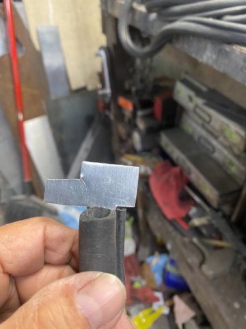
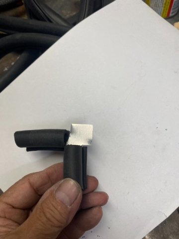
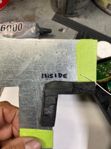
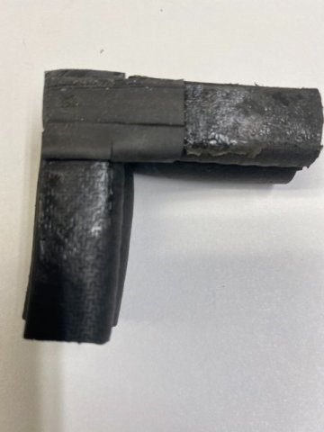
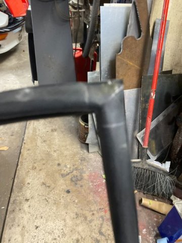
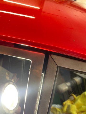
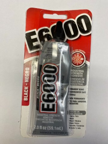
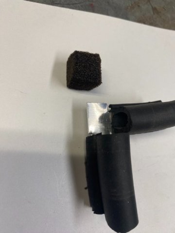
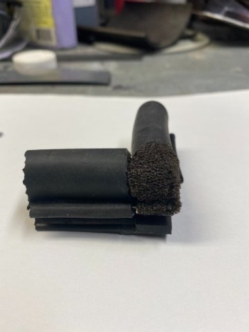
Precision Door Weather Stripping I found out that the Precision Door Weather Stripping was not doing its job. It seemed too hard and not sealing the interior from air leakage. Even after adjusting the Upper Chrome Window Channel inward to the Maximum Adjustment. So I decide to look for a Weather Stripping Replacement. I found an Universal Automotive Door Weather Stripping gasket on Amazon. Two of these Univerisal Weather Stripping Gasket are needed for both sides(Left and Right. This Gasket was soft but large to handle large door gaps. This style of weather stripping is used on most late model vehicles. The only problem was the 240z has a Right Angle-90) degree on the Upper Rear Corner of the door opening. The gasket was made for Slow Sweeping Corners. So some fabrication of the weather stripping would be necessary; Pic of Precision Corner Section which made by Vulcanizing rubber to create the Right Angle section. Precision Door Weather Stripping gasket First, A DoorTemplate had to be created to make the Right Angle Corner Piece which will hold both ends of Weather Stripping. This template will be used only for the constrution for the Right Angle Rubber Weather Stripping portion. A Corner Template made of 22 gauge sheet metal will be made to hold the two parts of the Corner Weather Stripping. This thin sheet metal right angle piece will inserted into in the slots of the each end of weather stripping. After Trial Fitting, this piece will glued with E6000 to fasten both ends of weather stripping forming the Right Angle or Corner Piece. Trimming of Connector piece to Fit.. The Connector Template inserted into both Weather stripping ends to Corner piece. A Foam Square was cut out of 1/2" Soft Foam to fill the Corner Gap between the Two Weather Stripping Edges. Note, this Right Angle Connecting piece will become a permanent part of the weather stripping after glued all together(connector piece, Foam Filler and both Edges of Weather Stripping} with E6000 adhesive. Test Fit of Weather Stripping on Door Template without Corner Connector. This Template is flipped over to create the opposite( Left) Door Template. r The Best Rubber Adhesive that I found is E6000. It is made by the same manufacturer makes Shoe Goop. It can be found on Amazon. If you ran a bead of E6000 on piece of wax paper and let dry hard. Then, peel it off the wax paper and you can stretch it 3 times its original size!! There are two versions of E6000 -low viscosity and high viscosity. It depends if you want the glue to fill in gaps or stay on the surface. Interior View of the Door Template with Weather Stripping installed Note-a Right Angle Corner Bottom Piece was made from 1/16" rubber sheet which is glued to lower side of the Right Angle Connecting piece to provide a Bottom Sealing Surface. Exterior View of the Corner Section Test Sample Section Note-Foam Gap Piece installed. E6000 is used to attach both weatherstripping edges to the Right Angle Connector and later gaps and edges will be filled with E6000 to prevent water intrusion. Top View of Weatherstripping Corner Test Section without Construction Template Testing Weather Stripping by shining Fashlight along window sealing edges *Light shining through area with no gasket Right Side Door Weather Stripping installed on vehicle. I have not Road Tested the car to check for Air Leakage or Water Leakage yet. Will let you know the results of both tests when they are completed.
-
Rayaapp, I am curious "Has your Gap insert made a differance in additional air flow for your AC system?" Toolman
-
I found this Four Part Video of a Complete Body Restoration of a 240Z car. This series of videos gives a good idea of how much work it takes to perform body restoration. The individual demonstrating the bodywork is a very skilled artisan and uses some specialized body tools. He repairs most of the bodywork with his years of skill. In some cases, a individual not as skilled could use reproduction Z body which are now available in the USA. As I found out later, I think these videos were made in Switerland. European and Asian countries have Vocational Apprentice-ship Education Programs that student start into their selected vocations( plumping, electrical, automotive bodywork,etc at age 15. So the student starting learning a vocational trade at least 3 to 4 years ahead of vocational schools in America. Unfortunately, most people tend to look down on individuals who go to Trade Schools instead of College. Yet, they can make a Six Figure Income at their Trades. Video#1 Video# 2 Video#3 Video# 4 rotisserie To work on the Z Floor Body Pans, the Two Methods most often utilized is Car Rotisserie or Tilt Rotisserie. A Car Rotisserie costs over $1000 or you could rent on or make your own (using two engine stands). The choice is to construction of a Wooden Tilt Rotisserie. It built using 2" X 6" lumber and some plywood costing about $80 from Home Depot. Putting car on the Rotisserie I hope these You Tube videos were interesting for you. If you have any questions, please ask and try to answer them.
-
AC compressor LSA/ZL1 2012 in 260z
toolman replied to christianmoller's topic in Gen III & IV Chevy V8Z Tech Board
christianmoller, I forgot to include the compressor # SANDEN SD7B10 (7176). Kwik Performance website also has installation diagrams that give dimensions the compressor mounting on LS motors. This will enable you to determine if this kit will find in your particular vehicle. TOOLMAN -
AC compressor LSA/ZL1 2012 in 260z
toolman replied to christianmoller's topic in Gen III & IV Chevy V8Z Tech Board
christainmoller, Check out my posting under Heavy Duty Frame Rails underGen iii & IV Chevy V8 Tech Board Postingn 17 and 18. They show y AC installation in my LS3 6.2L 240Z. I tried several Aftermarket AC Kits that would not fit as I made my own motors mounts and custom made front sub frame( constructed from 2 1/4" square tubing. The smallest AC Compressor that I found was a Sanden AC compressor which is only 7 inches long total length (comprssor with clutch). I used a Kwik Performance Ac Kit but the mount can easliy fabricated by yourself. I was rushing to enter my car into a car show so did not have time to measure and try and error the mount construction. But notice that you must use Chevy truck type water pump and longer harmonic pulley to match the belt location. The posting goes into the details of the AC Installation. I hope this answers your questions, if not post any more questions that you may have. Toolman -
fturbo930, Check out -The guy with Larry Chen walkthrough Toyo Tire booth claims the Green 240z has a Lamborghini V12 motor in it. Unforturnately, the hood was not open. I guess we will never know for sure. Green 240Z video at 4:29 Toolman


.jpeg.80b83017498b1a740b0b8bd3b73a02e3.jpeg)