Leaderboard
Popular Content
Showing content with the highest reputation on 10/22/24 in all areas
-
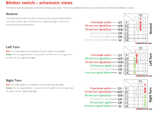
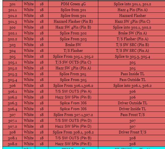
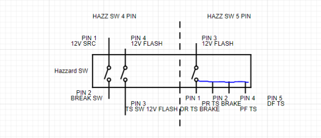
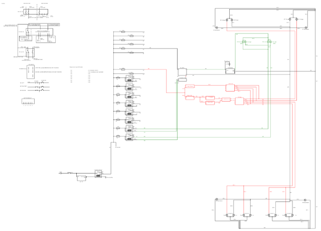
A few notes before I get into it 1.I am rewiring my car from scratch. So I have no clue what color wires correspond to what pins, or what year switches I am using 70-78 2. I'm not using the stock taillights, I only have an off, high and low signal, all red(Think Semi trailer lights). So the way I wired stuff might be different for you 3.I feel that if you understand the concept of what I am showing below you can adapt what you have to create something similar. I am an idiot when it comes to wiring, but I got this to work for me so feel free to copy it at your own risk haha. This definitely isn't stock Hazard switch (Ignore the PinX stuff for now, That is how I am keeping track of what wire is going to what pin on the connectors I have) I see the hazard switch as the first step in how the power is routed. The switch has two different states (Noted by the vertical dashed line in the image above), on and off, each with it's own outcome. Hazards on: (Right side of above image) 5 Pins should be connected on the switch when the hazard switch is on/closed, use a multimeter to test continuity between all the pins, and note which ones are connected. One of the pins should receive 12v + from a flasher unit (I am using a PDM (Bussman31s002) to get fused 12v power, then putting that into a 3 wire flasher unit that is adjustable to set the timing of the flashes). So when I have my hazard switch on, power flows through the pdm, then into the flasher, into one of the 5 connected pins on the Haz SW, then a wire out to each of the 4 turn signal lights. This also kills all connections to the "Off" side of the switch. In my case, this disables the turn signals, and brake lights. Hazards off: (left side of above image) there are going to be two sets of two pins that are connected when the hazards are off/closed. Use a multimeter, check continuity, write it down. Feed one of the pairs with fused 12v+. The pin that is connected to the 12v+ gets a wire that is spliced into 2 different locations. Location 1 is the brake switch. Location 2 is a second Flasher unit. These two wires then come back together to feed the Turn signal switch, one flashing, one constant. When the switch is in this position, everything on the right side of the above image is no longer connected. Turn Signal Switch The Turn Signal Switch works off of two inputs 12v constant (Connected to 2 pins that should correspond with your Brake lights, and will disconnect from one of the pins if the turn signals are on in that direction) and 12v flashing (Connected to either the front left and rear left, front right and rear right pins, or no pins at all depending on the location of the stalk. So, for me, If my brakes are on, I get a signal to the "high" side of my tail light. WoodworkerB's website is invaluable. I recreated all of his diagrams with the corresponding wire color of my switch to use for my own project. https://woodworkerb.com/home/datsun-240z-rebuild/blinker-detail/ https://woodworkerb.com/home/datsun-240z-rebuild/datsun-240z-multifunction-switches/ Below I have a schematic of what the whole thing looks like, minus the detail of what the internals of the switches are actually doing, as well as the pinouts. (right most column is where the wire terminates, to its left is where it starts) Looks like the images are tough to read. DM me if you want a full size copy. Let me know if you have questions, or tell me that I'm wrong haha, The harness still in the basement so I would rather fix stuff now than when it is in the car. But as is the lighting system is functional, I pulled out a bunch of stuff to test it all.1 point

.png.00ba7668e3b86ef19d6564579d3fca92.png)


