

RTz
-
Posts
2941 -
Joined
-
Last visited
-
Days Won
23
Content Type
Profiles
Forums
Blogs
Events
Gallery
Downloads
Store
Posts posted by RTz
-
-
1 fast z,
I'm a little surprised. I'm sure you've lost track of how many people told you that you "can't" join two heads together. Or, that it "won't work" and "why". I respect your candor for having the gut's put that monster together....
Whether its the right way or not, you're the LAST person I would expect to kick this under the bus.
-
I just wanted to make a thread thanking the admins for keeping this site on track and with a open and somwhat non judgemental atmosphere.
Amen!
-
Prior to designing this manifold, I consulted with a few people. One of them, not surprisingly, was Braap. I asked him to list the items he’d like to see addressed. Near the top of his list was raised ports.
I recently contracted Braap's services to properly blend the ports into the larger, raised runners, and also asked him to summarize his work....
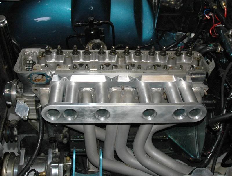
Today after church I was able to focus a little effort on matching up the custom N-42 head to the intake manifold. When Ron started the design phase of this intake, he coordinated with me concerning specific details in an effort to meet his goal of building an intake that would be a definite performance improvement over stock taking into account several details that we both feel need to be addressed in a true performance induction system. One of which is an effort to straighten the port. To do that, we remove material from the roof of the port opening, leaving the floor alone. With that, Ron designed this intake manifold with a raised port centerline. This aligned the runner and port floors with each other so when port matching, material will be removed from the roof of the port effectively straightening the port a little aiding in air flow not only in port size but in port shape AND approach.
In these pics you can clearly see the concept and end result.
The manifold runners and plenum base mocked up on the head in the engine bay…

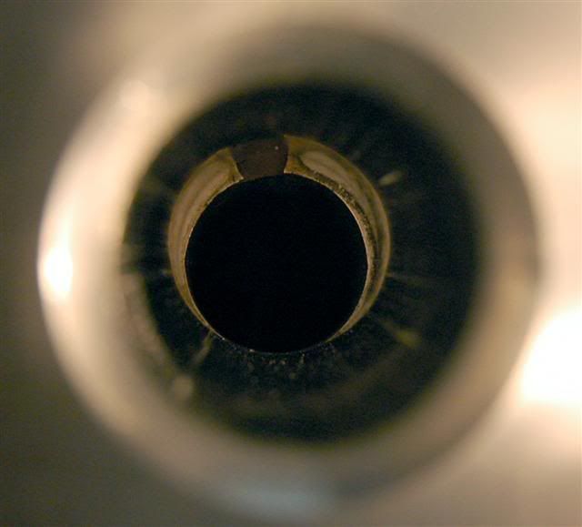
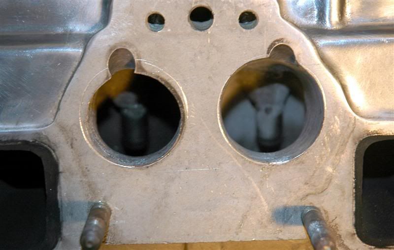
These next two shots show the port mismatch and centerline bias of the port. In the top shot, note the port offset bias… in the lower shot you can see the virgin port with scribe line on the left and the roughed in port on the right.
.
.
.
This would probably be a good time to mention runner size....
1) N42 manifold runner area is approximately 53% of the intake valve area (stock 280z).
2) In my observations, OE manifold equipped Z’s generally run out of breath shortly after 5500 rpm or so, depending on the build.
3) I’ve seen enough data to suggest that number 1 and number 2 are related.
4) A priority of the design was to build a modular manifold so that runner diameter and length could easily be tailored to the specific engine.
The manifold pictured above uses 1.5†ID runners. This puts runner area at 74% of valve area. The runners are also 6†long (OE averages around 7.25â€). This should compliment the intended use of the first engine. Dyno testing will follow to confirm success or failure.
We’re looking into building adjustable length runners for the second manifold and, of course, we’ll share the results.
-
-
Ron,
I will email you directly soon.
Les,
Haven't heard from you... you still need a timing map?
-
Thank You.
-
Another way to say it... the centrifugal SC's boost goes up with the square of its speed. Hence, double the RPM is 4 times the boost. So, if you want max. boost to be 10 psi and max. operating RPM is 7000, then at 3500 you're only getting 2.5 psi. Furthermore, you still have all the parasitic drag at low RPM... without the boost to go with it.
I'm with Pete... I don't fancy centrifugal SC's.
-
Nice work Hugh!
-
Mike,
Don't forget '74 1/2's had the larger tranny tunnel for sneaking the exhaust up a little higher after installing a T56, and the lower core support being lower for getting a little more radiator up there.
-
All of the 240 "features", without those gawd-awful bumpers...lol:mrgreen: [/b]
Easy fix
-
Justin,
The dimensions on my manifold page don't help?....
http://forums.hybridz.org/showthread.php?t=117607
I can provide you with .DXF's if it makes it any easier.
-
'74 1/2 260....
All the 280 'features', with none of the EPA hassles
-
Les,
Your point of view doesn't seem to mirror my own.
Here’s how I see it...
On November 29th, you emailed me and asked if I had a timing map for an LT1. On the same day, I returned the email. I explained that, while I don’t have a map, here are the necessary numbers for you to plug in the appropriate places. I also included my phone number and told you to call me if you had any questions.
If you did not receive my email, I apologize. These things happen. Let me know if this is the case and I will resend. If you did in fact receive it, you should have called me or email'd and said “Hey Ron, thanks for the help. I could use a little clarification though, etc, etcâ€.
By not responding, I was left with the assumption that you were happy. Why would I think otherwise?
If you still need help with the map, PM me and I will build one for you. All that is requireed is a little communication. Deal?
I've searched and searched, but it seems that Wolf 3d is targeted for import motors.I would venture to say, in Australia, V8’s are the minority. This doesn’t mean they don’t care.. V500 has *eight* injector channels and *eight* ignition channels. Not many of the midrange systems do. It normally requires about double the money to get into a system that can make the same claim. What you're witnessing is simply a reflection of the popular market.
Wolf seems to not have any dealers in Los Angeles. Los Angeles has a few car enthusiasts,
, I'm a bit surprised by this...I emailed Wolf in AU, after I told them where I was I think they were embarrassed that they have no support in LA.
Not embarrassed. Apologetic, maybe, but not embarrassed. Don’t forget, Wolf is an Australian company. They have a very respectable reputation in their homeland. They only recently decided to make an effort to grow in the US. This takes time. You can’t just twinkle your nose and have dealers instantly appear all over a country the size of ours.
FAST ems lets you adjust the fuel map with a quick tap on the keyboard based on the wide band reading and what you want the AFR to read at any given fuel map position.
This feature is partially marketing. The problem with this method is that YOU have to set the target value. If you stick with the common ‘12.5’, more often than not, you will leave power on the table. Some engines respond well to a flat 12.5... some don’t. Some like to run leaner down low and richer on top. Some are opposite. Either way, you still have to do proper testing/evaluation to find out what YOUR motor wants.
The reason we spend the money and take the time to install these systems is to wring out more performance than OE, yes?. In 99 cases out of 100, you will not BEAT the factory numbers with simplistic tunning of ‘target values’.
Since you already have an LM1, this is still very easy to accomplish with Wolf. Using the arrow keys... , the pulse-widths increase or decrease incrementally. This can be done with an ENTIRE load band, or just an individual cell. Holding down the shift key will make larger jumps. With this strategy, you can have a drivable initial map within minutes.
I hope this helps you. If you have further concerns, don't hesitate to email me.
-
Tease!
-
Ron,
You are assuming that heat is conducting from the intake manifold material to the element portion of the sensor.
A little more than asssuming. A heat gun pointed on the element raised temps to 160-ish. Pulling the heat gun away, the temps lingered, dropping about 1 degree per second. AS SOON as I touched the brass mount, the temperatures starting coming down semi-rapidly. Even though the testing was remedial, I feel pretty comfortable saying that the attachment surface can influence the readings.
Also, air upstream of the TB has not picked up heat from traveling through the intake manifold.
I agree. This is why I think every position is a compromise. Its comes down to which compromises you're willing to live with.
Same when you shut the car off to pick up a six pack. The air in the intake gets much hotter than the air upstream of the TB.
Agreed. But ALL of that air is gone within 2 crank revolutions. Its gone before the engine even starts.
I don’t see accurately reading this condition as one of the important compromises.
Although, I will concede the manifold is probably substantially hotter in that scenario and thus, the new incoming air should be slightly hotter.
This is why mounting it in the intake, along with an air temperature compensation algorithm running in your ECU is important (most all do this).
Understood.
I would be 'with you' if it weren't for the influence that I see coming from the mount point.
-
Found this http://www.motec.com.au/drawings/m32.pdf which answers one question, probably, but I'm wondering what coils I have. LS2? (see pics above)
Those coils are definitely Denso. Not certain what application, though. $20 say's the pin-outs are the same...
A Engine Ground
B Logic Ground
C Signal
D 12v
-
2) 2 separate EDIS-4 systems, but with two 36-1 trigger wheels mounted on the “cam”, or dizzy, 180 degrees out of phase from each other i.e. the trigger wheels spinning at half crankshaft speed. The EDIS modules would just see the RPM as half what the engine is actually turning, i.e. your 8200 RPM, EDIS would only see it as 4100 RPM.
Braap/Hanson,
As you mentioned, dwell might be compromised.
The way I see it... its common practice to taper off the dwell at higher RPM. Peak ignition demand is typically at peak torque... no need to ask the coils to be fully saturated when demend is lower. This just makes them run hotter (due to increased duty cyle) and shortens their life unnecessarily. I would be very surprised if Ford designed EDIS with a fixed dwell. That said, if you’re cam driving EDIS, it would think the engine is at half actual speed. This scenerio *might* put the programmed dwell in the wrong RPM range. Then again, it might not. Only testing will determine that.
It would be interesting to map an EDIS system.... add it to your list Braap
-
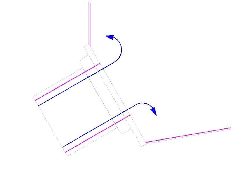
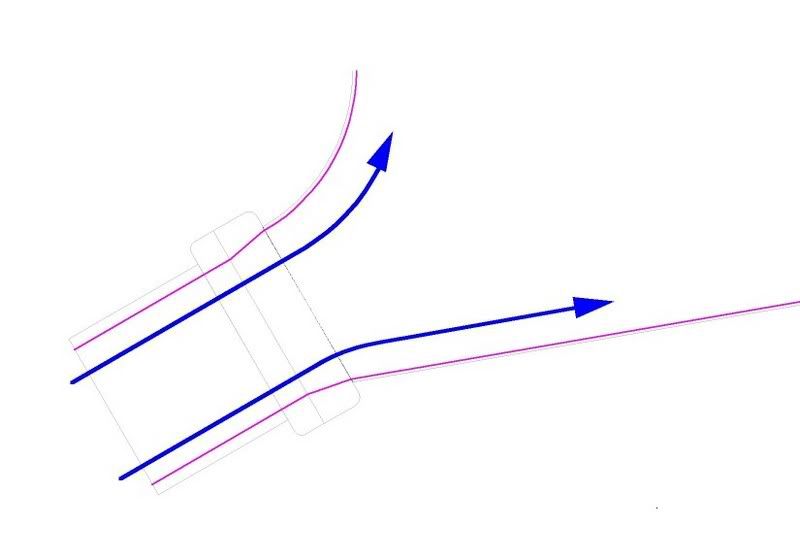
This manifold is heavily influenced by its throttle body.
A scenario I wanted to avoid....
...When a TB is attached to a 'flat plate' the incoming air has a tendency to separate directly after the TB, leading to turbulence (which can lead to uneven cylinder distribution).
My decided approach was to use an oversized TB to attack this two fold. First by slowing the air down, and second by allowing the walls of the TB to closely match the inner walls of the plenum.
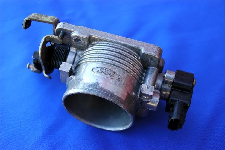
Using a 65mm Ford TB (‘95 Crown Victoria) I was able to keep the taper after the TB within 10 degrees...
.
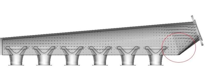
Another 'feature' I wanted to avoid is protruding velocity stack's.
As demonstrated by "turbobluestreak" in this CFD....
...there is a high pressure area that develops between the TB and cylinder one.
Certainly this does not happen with all internal velocity-stacked manifold’s. My point is simply... without laborious testing and expensive test equipment, it can be risky.
-
you kidding?
Are you?
-
Links down, anywhere else that info might be available?
What info are you looking for?
-
Try and bargin w/ the towing company. I think at best they would get 200 for it. Offer them 400 and see what happens, otherwise forget it.
I agree. Its a game. Negotiate with them.
-
Anyone find it amazing, per this poll, that one out of every three Z's doesn't run?
-
You ca get good prices on Wolf ECUs Ron???
I'll knock $100 off retail to anyone donating $25 to HybridZ in the preceding 12 months.
-
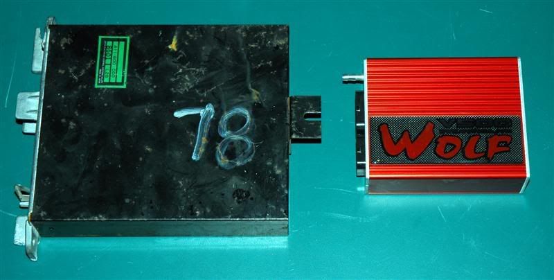
Tim is right... there is nothing to re-flash.
If you're the creative type, you can stuff a Wolf V500 in the OE case....
Let me know if you need one of those
Pic request: L series wired tucked
in Nissan L6 Forum
Posted
.
.