Zmanco
-
Posts
1568 -
Joined
-
Last visited
-
Days Won
1
Content Type
Profiles
Forums
Blogs
Events
Gallery
Downloads
Store
Everything posted by Zmanco
-
No one else is asking so I will: why do you need to replace your head when you have a bent rod?
-
Contact DIY Autotune - they sell kits and assembled too - maybe they do repairs? Matt is often on this board so may see this as well. But how do you know the injectors are staying open as soon as you apply power? I'd say it's far more likely that you have a wiring problem than the CPU is bad, unless the tuner is flat out lying to you, which is probably not the case. If the MS system was built using a Relay board, then I'd start with looking over all the wiring, looking closely for anything that worked loose, etc.
-
I get C&D and R&T and don't remember seeing this. The power to displacement ratio goes up by 15% based on their numbers if I did the math right. I believe the Mercedes 4 valve 5.5 L V8 is rated around 380 HP so 440 from 2 valves is pretty impressive. Of course, I'm assuming they're staying with 2 valves per cylinder. Would it be possible to go add a third for intake with only 1 cam? Hope that's not a stupid question - I know next to nothing about GM V8s.
-
I give up - I have the same year car as you, I did the same mod as you, and I experienced the same thing as you - a relay was always on when I reconnected the battery. In my case it was the factory fuel pump relay. Yet because you have added as second relay to control the fuel pump you feel that the factory fuel pump relay can't be the problem. I STILL don't follow your logic, but that really doesn't matter. Since you're sure that it's not the fuel pump relay, I'm very curious to see which one it turns out to be.
-
Not sure I follow your logic. I experienced the same thing with my car after essentially the same mod (I made my own plug since MSA didn't offer it back then) and the issue was the factory fuel pump relay was always on. I removed it to solve the problem. When I later needed an electric fuel pump, like you, I created a separate circuit to power it. How do you conclude that it's not the fuel pump relay that's clicking on and staying on in your car? FYI, I'm traveling so can't go look at the car, but I'm pretty sure the relay you show in the picture IS for the fuel pump. Disclaimer: it doesn't matter to me whether this is or is not the issue - I just don't follow your logic.
-
I too ran an MSD6A with triple webers and my experience mirrors Jon's. However, I will say having just finished an EDIS swap that for not that much more money, you could go EDIS which really is more stable and doesn't have the dwell limitations of a single coil design. Plus, the parts are available at just about any JY if you have a failure. In fact, if you have a decent condition distributor, you might be able to sell it and the MSD box and make a slight profit Although you didn't ask about EDIS, I'll add that the only downside I've found with EDIS so far is if you run an ECU like Megasquirt that uses spark cut to implement rev limiter or boost control, you have to switch to fuel cut. EDIS has a fail safe mode that defaults to 10 degrees advance when it doesn't receive any signal. While this is probably a great feature for a Ford Explorer, it's incompatible with spark cut.
-
I did the same swap some time ago and just checked my notes to refresh my memory. On my 73 the fuel pump relay was always on after the swap. At that time I was only running a mechanical pump so I just removed it.
-
Yes, this is normal. The 1k ohm resistor will limit the current enough that a typical test light will not light up. If you are trying to measure continuity through a resistor, then you need a digital voltmeter (DVM). You can get a decent all around version for about $25 at most auto parts stores, and an el cheapo at harbor freight for $2-5. Perhaps you should start over with what the problem is...
-
If the car is a 71-73 then you need the tach adapter. The stock wiring triggers the tach off the negative side of the coil, but since the MSD fires the coil multiple times per ignition event at slow speeds, that will no longer work, hence the need for the tach adapter. Edit: just noticed you have a 260z which has a voltage triggered tach (the 71-73 are current triggered). I think you'll still need the adapter as the white trigger wire off the MSD box will probably not have a large enough voltage swing to trigger the factory tach. I'd still try it, but doubt it will work. Given the adapter is around $50, you might want to invest that money in a new tach instead which would trigger off the MSD box's white wire.
-

Keyboard Air Duster Used to Cool Fuel Rail
Zmanco replied to jas280z's topic in S30 Series - 240z, 260z, 280z
I'm still using the stock fuel rail. I also have the webbed intake manifold with the factory heat shield between it and the exhaust manifold. I'll pick up on what Dave said and add that the solution is a combination of things, probably not any one silver bullet. And just to be clear, I have no problems starting after a heat soak now that I add more fuel. As RTz said, it's not likely a vapor lock problem, and if the OP is using an aftermarket EMS, he should be able to tune around this. -
Keyboard Air Duster Used to Cool Fuel Rail
Zmanco replied to jas280z's topic in S30 Series - 240z, 260z, 280z
What EMS are you using? I find that after the engine heat soaks it's hard to get a reasonable mixture for the first minute or so. This was a mild occasional issue when I ran NA, and now that there's the additional heat of the turbo it happens often. I've added the factory blower with a manual switch which I just turn on when I run into a store. It helps a little but not as much as I'd like. Before that I tried a manual override for the fuel pump. My theory was that the fuel in the rail was very hot and hence less dense which leaned the engine out until cooler fuel circulated through it. But that made absolutely no difference. My theory now is that the real culprit is the heat soak of the injectors themselves and that it takes a minute or two of fuel passing through them to cool down and hence for the amount of fuel they are injecting to be accurate again. To combat this I've extended the ASE (after start enrichment) time with some extra fuel via Megasquirt when the coolant is over 195F and this has helped a lot. If you're running with an aftermarket EMS I would suggest you can probably solve this via tuning for hot starts. -
I contacted ATP Turbo and asked them for advice. Here's their response: This has me thinking about my exhaust. The downpipe attaches to the wastegate via a 3" V Band. It's a full custom exhaust and it lines up perfectly and it's easy to put the V band on. But perhaps there's enough play in the motor mounts to put stress on it and work the nuts loose? There's no flex joint of any kind. Is this something that is typically required?
-
There are two issues: which pin to use to connect to whatever tach signal you're using from the engine, and then how the MS board is configured to process the signal. As Matt said, if you are taking the tach signal from the coil, then you need the board configured to use the opto-isolator input. It's been a while since I did this, but I believe at a minimum you have to move a jumper. There might be a wire that needs to be added too - I'll let Matt take it from there as he does this a lot more regularly than I do I know this is all documented on the MS website as well.
-
I measured 3 at a time in parallel at the MS relay board (much easier than trying fit my hands under the fuel rail) and saw 1.2 ohms for each bank which would suggest they're somewhere around 3.5 ohms individually. Edit: I tried driving with threshold at 1.4 ms and pwm current limit as high as 40% last night and there were intermittent stutters. I bumped threshold up to the next step 1.6 ms (it increments in .128 ms chunks) and pwm current limit down to 30% and that solved it. But it didn't want to start reliably until I either bumped the threshold up further or increased battery voltage correction to 0.400. I wish I had a spare injector to send to you Pete, I'm really curious to see some objective measurements for these. In the mean time I think I'm just going to run them with resistors as that's stable and reliable.
-
Thanks Nigel, I called and they have a 57 mm stud that's not on the website so ordered those and the nuts. Perhaps my mistake was using standard non-locking nuts? Interesting that I haven't read of anyone else having this problem.
-
Pete, thanks for helping me see the flawed assumption I made: I forgot that the coil's current will saturate before the injector opens fully. So my procedure clearly won't be accurate at all, as my 1.9 ms measurement indicates. Actually, I've been operating with the resistors and no PWM control for some time now with a 1.500 ms opening time and the tune is very good, with the exception that at idle and other low MAP conditions, the amount of O2 correction required varies a lot from hour to hour, even minute to minute sometimes. FYI, normally I leave O2 off below 1100 rpm but turned it on only for these experiments. At idle, PW is typically in the 2.2 - 2.3 ms range, so even changing the opening time by .1 ms makes a significant difference in how much fuel is "fixed" vs. controlled by MS calculations, hence my interest in getting a more accurate setting for these injectors. I'll try running with the values in your spreadsheet for the other Bosch injectors and see if I can get a more stable low MAP tune. The worst case is that I just go back to what I have now which all in all works pretty well.
-
I'm going to put new studs in: http://www.mcmaster....#studs/=7ueqej. Is general purpose steel acceptable for the exhaust manifold? Looks like steel insert lock nuts aren't available in an M10 but this is: http://www.mcmaster....95a240/=7ugfrc. Is class 8 steel ok for exhaust manifolds? And any reason why I shouldn't also make locking tabs out of shee metal for a belt and suspenders approach? I really don't want to pull the head again for this.
-
Jon, I'm with your approach. I'd go a little further for F1 since it positions itself as the leader in technology, and give each car a budget of X amount of energy to be used for the race. Make sure it's enough so that this doesn't become a fuel economy race, but not so much that it encourages waste. Then let the teams determine how best to use it. Some might use it all in the form of gasoline, some diesel, some hydrogen, and I'd expect some would use some hybrid combination. Plus, I would expect some form of KERS would become quite common. I think there would be some very creative approaches, albeit there would likely be some big discrepancies between the teams in the beginning as some would really struggle with this type of new approach. But if F1 wants to remain relevant as the world becomes more and more concerned with how it uses energy, this would leave them well-positioned.
-
Do you think I can use some sheetmetal such as what I'd get at Lowes? The locking tabs I took off seemed to be more malleable, but I'm not sure where I'm going to find that material around here.
-
I'm using studs. Looks like there are a variety of metal locking nuts: http://www.mcmaster.com/#hex-locknuts/=7ubgxo I see distorted thread and flex-tops. Any significance between them in terms of how well they tolerate vibration? Also, any suggestions for the wastegate bolts? The threads are completely enclosed. Is there any point to using a locking washer or will the heat eventually render it useless?
-
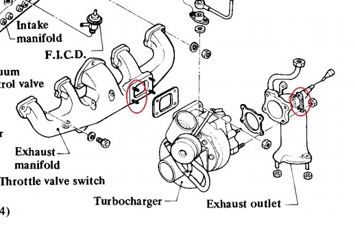
I've had a recurring problem with the manifold stud bolts coming loose on the turbo. FYI, the turbo is a Garret T3/T4OE so there is a 1/2" spacer along with 2 metal gaskets - one on each side of the spacer. I'm getting ready to pull the head so I'll have access to them and wanted to know what others have done. When I tore down the stock engine I remember there were 2 pieces of soft metal that were bent up against the bolts to prevent them from turning. This is from the 82 turbo FSM and shows them on the 4 bolts for the downpipe but not for the manifold studs. Should I perhaps be adding them? Also, the five bolts that attach the internal wastegate to the turbine have come loose as well. I'm wondering if this happened because the manifold bolts came loose first, and then the extra vibration worked the wastegate bolts loose? How have the rest of you secured your turbo bolts both at the manifold studs and wastegate?

-
I know I could just fall back to using the resistors, but I still need to determine the opening time. Do you think the approach is valid, at least good enough for those of us without current probes for a scope? Also, if my numbers are accurate, does that make sense? When I look at the values you measured in your other thread with the opening times spreadsheet, most have a pwm time threshold of just a few tenths of a ms more than the opening time. In my case, I'm seeing nearly 1 ms longer.
-
I've been running with Ford 5.0L 437 cc injectors (280-150-400 / EOSE-A1A) with RESISTORS and have noticed that especially at idle, the AFR is very inconsistent from time to time. In other words, as MAT and load changes, the AFR moves a lot. No amount of tuning the VE table resolves this: I can get it nearly perfect one day, and then another day it's pretty far off. It dawned on me that if the opening times were not accurate, then VE wouldn't have a linear relationship to how much fuel is injected. So I ran the following test. I drove the car, came back to the garage and let it idle to get the underhood temps stabilized. I allowed O2 correction to operate in the idle region so I could get a numerical value for how far off the mixture is. FYI target AFR at idle is 13:1. I bypassed the resistors and turned on PWM control and found that as I increased PWM Time Threshold the O2 correction would move negative - in other words, increasing time threshold and not changing anything else caused more fuel to be injected. It didn't level off until I got to 1.7 - 1.8 ms. I took this to mean that the injectors are slower than average. With time threshold at 1.9 ms, I then experimented with changing the opening time. My theory was that when opening time is correct, then the change in VE should be linear with O2 correction to maintain a given AFR. I tested this by using the scaling feature in Tunerstudio to change all the cells around the idle point in the VE table by either 1.1 or .9 to cause a 10% change and then watched how much O2 correction actually changed. It turned out that it didn't correlate 1:1 until I shortened opening time to 0.900 - 0.950 ms. So I have two questions: 1) Does my methodology for determining PWM Time Threshold and Opening Time without a scope make sense? 2) I'm confused by these times. 1.9 ms for time threshold seems long, and indeed the two injector driver transistors were noticeably warm to the touch - more than those around them. Also, it seems strange that the opening time is so much less than the time threshold. Note: I debated starting another thread, but thought that this was relevant to how one might measure these times without a scope, so posted it here. I'll be glad to start another thread if this is too far off the original topic.
-
Tony, I've already done the Honda Civic fan upgrade and it was a significant upgrade in my '73, but your comment has me wondering about the 180W 280ZX. I've never heard that mentioned for a swap into early Zs. Does it move more air than the Civic fan? Are there any modifications required to make it fit? In other words, would it be worth doing even if I've already got the Civic fan? I don't run AC anymore, but any extra air flow in the cabin would be great!
-
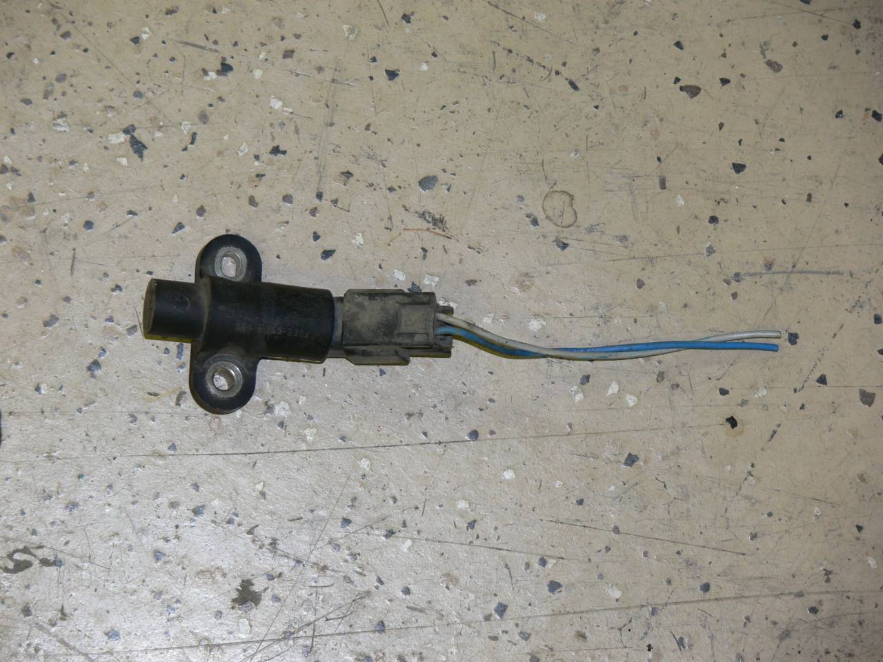
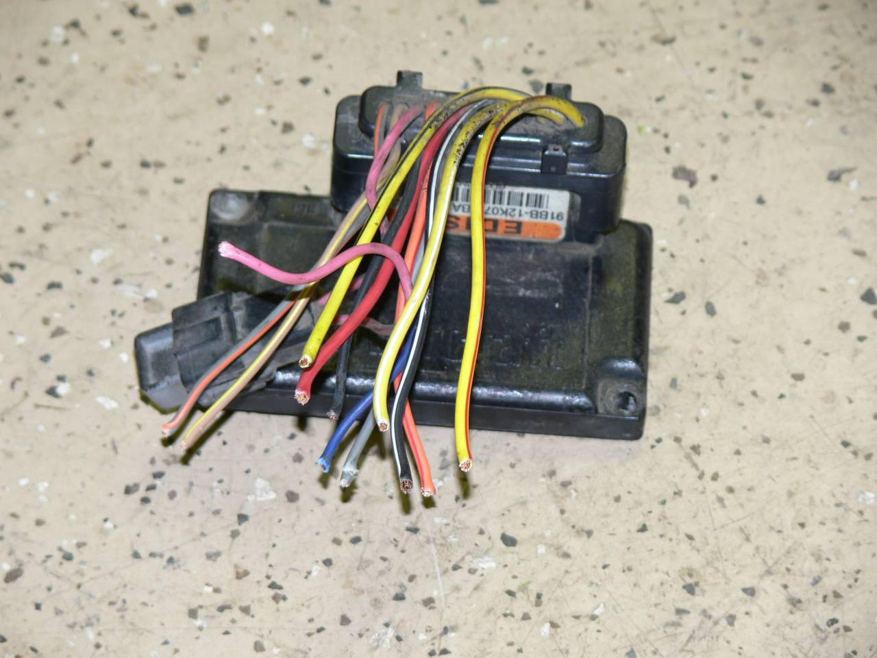
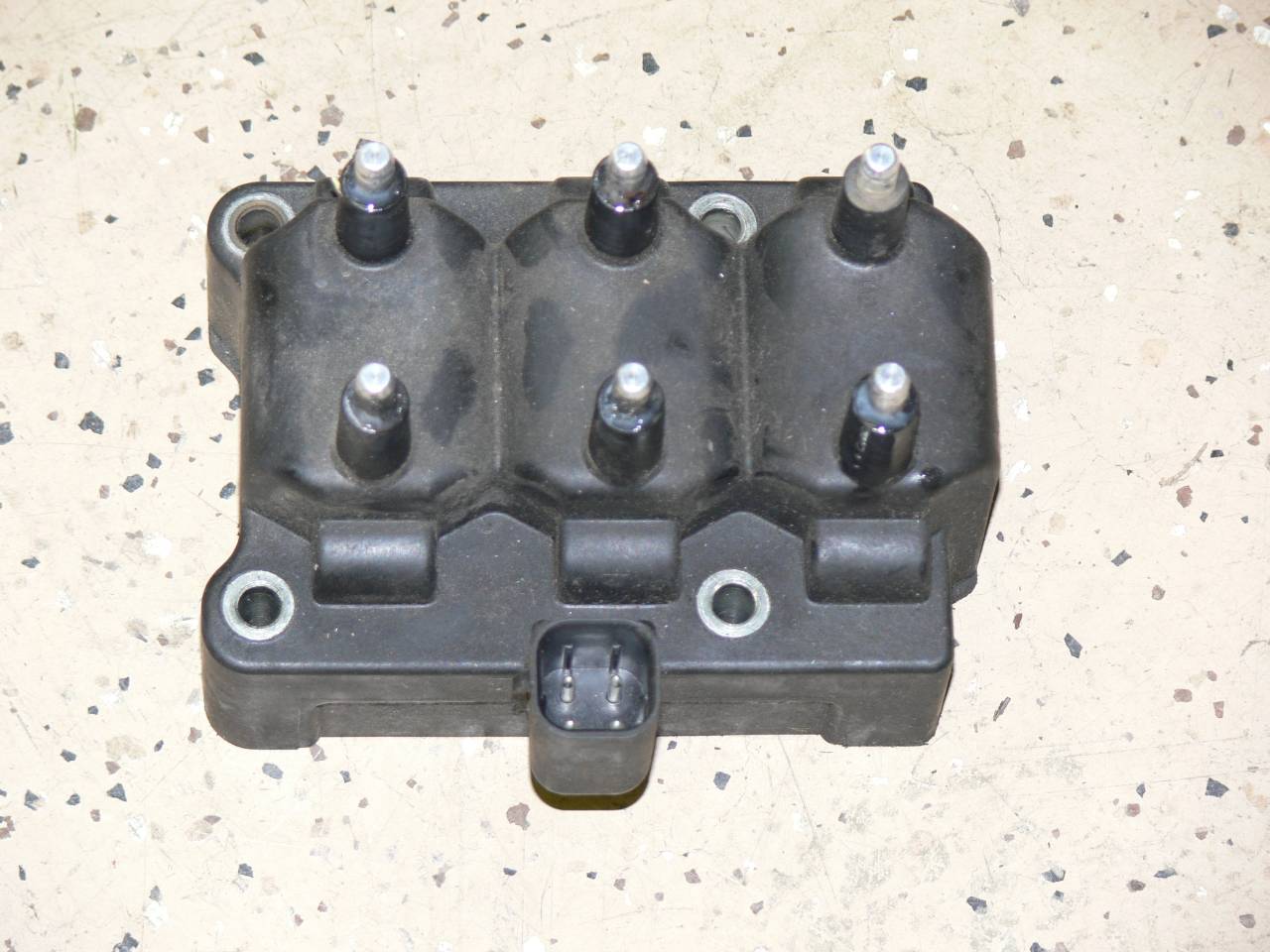
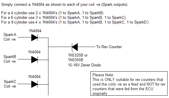
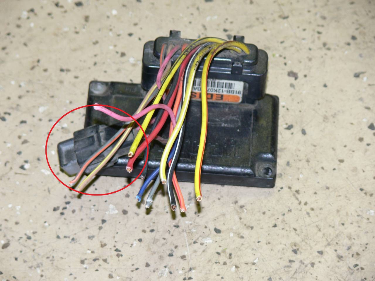
I just finished converting to EDIS for my turbo L28 and thought I'd share some lessons learned. There's a lot of information about EDIS out there, but some of the wiring details were unclear to me until I actually got it on the car and tried to start it. This led to further trial and error which I'll hopefully help others avoid. Disclaimer 1: There are many sources of EDIS components besides what I used as well as methods to wire them up. This is what worked for me - I'm sure there are other ways to approach this that will work equally well. Disclaimer 2: There are many other threads here and on the Megasquirt sites that discuss the theory of EDIS and provide the basics for the install. You should read those before starting. Now, on to the the Lessons Learned: 1) The easiest VR sensor to find and remove at the JY was from a mid 90's Ford Escort or Mercury Tracer with 1.9L. Find one where the passenger side front tire is already removed and take the plastic fender shield off. It's much easier to get to the sensor that way than from the top. 2) The Ford Explorer EDIS controller from 4.0L V6 is mounted up front to the left of the radiator when facing the truck. It's not on the fender as some others have written, at least not on any of the trucks I looked at. 3) Chrysler mid 90's V6 3.5L has a coil pack with a flat bottom making it easier to mount than the Ford. I've read that some of their minivans do as well. I took the spark plug wires to get it up and running as my old distributor wires wouldn't fit its terminals. Hint: take the 3 short ones from 2 cars as you'll likely find the long ones too long. 4) Leave the device that's attached to pin 3 of the EDIS controller attached. It's a filter for the SAW signal. You may as well use it - Ford thought it important enough to include it. 5) Make sure the JY checkout person knows the controller goes with the coil pack and doesn't think it's an ECU. It was much cheaper that way. 6) I picked up 2 VR sensors and while they looked the same, the mounting holes on one had to be drilled out whereas the other was a closer fit. You might want to pick up 2 anyway as I'll guess that's the most likely part to fail and my JY didn't charge for it - I guess they considered it was part of the EDIS parts. 7) I never found a spec for how close the VR sensor needed to be to the toothed wheel, but in the end I settled on a roughly 1 mm gap. Closer is better so long as it doesn't touch. 8) Make sure you connect power to something that is live with +12V while cranking. Even though I knew this, I STILL goofed it up the first time and wasted time troubleshooting. 9) Revisit the rev limiter and boost limit settings on your ECU. If they are relying on cutting spark, they won't be effective anymore since EDIS has a limp-home mode which defaults to 10 degrees advance when it doesn't get any signal. You need to change to cutting fuel. 10) If you have a 74-78 tach, you'll need to use this simple diode circuit to get the tach to work. Don't bother with modifying Megasquirt - the factory tach didn't respond for me. I found it easiest to wire the diodes at the splices to the controller connector, but you could also do it at the splices to the coil pack connector. FYI, Digikey is a fast and cheap source for the diodes. I don't know if this would work with a 71-73 current-triggered tach since I didn't try it, although I don't see why it wouldn't work. I'll just add that it's not hard to swap a later 74-78 in place of it. 11) The polarity of the VR sensor matters. Its wires are blue and grey as are the two wires on the controller. You would think that these should match, BUT THEY DON'T! Connect blue to grey, and grey to blue. 12) The coil pack connector has a power lead and 3 thinner leads, 1 for each coil. Connect the black one to the yellow/black wire on the controller, the red to the yellow/white, and white to the yellow/red. Again, it's tempting to connect the matching colors, but then you'll have to ignore the markings on the coil pack for which coil fires for which plugs. 13) The three coils are labeled as 2-5, 1-4 and 3-6. The firing order of the coils is preset by the controller and is 1st: 1-4 2nd: 2-5 3rd: 3-6 and then the cycle repeats. Use this to determine how to attach the plug wires. Remember, the L6 firing order is 1-5-3-6-2-4. For a given coil, it does not matter which of the two posts is attached to each plug as long as the firing order is correct. Remember, EDIS is a form of wasted spark meaning that both plugs are fired at the same time but only one cylinder has air/fuel and hence generates power. 12) The connector for the coil pack has a several inch long device on the power lead. This is a capacitor which helps reduce electrical noise. On the other end there is the green power wire, and also a black one. Connect the black to ground so the capacitor can do its thing. Alternatively, you may find a stand-alone capacitor on one of the donor vehicles. I went this route simply because it was a cleaner install. 13) You should use shielded 2 conductor wire between the controller and the VR sensor. Attach the shield ONLY at the controller. Same goes for the PIP and SAW wires to Megasquirt (or whichever ECU you use). Again, connect the shield at the controller, not at MS. 14) Be very careful with your wiring and go slowly. I would recommend soldering the VR sensor and PIP and SAW connections and then shrink wrap them. It's also a good idea to solder the diodes for the tach circuit as solid wires can work loose in a crimp connector over time. For the rest, crimp connections are fine. Then cable tie the wires into harnesses and make sure they don't flop around. Lastly, this project took A LOT more time than I had expected. Perhaps it was a few other "while I'm at its" that crept in, but in any event, make sure you budget enough time to do it right. You don't want to be on the side of the road troubleshooting your hurried wiring. Edit: I should have added up top that I used Derek's EDIS kit which includes the 36-1 wheel and VR sensor mounting hardware. You can learn more about it here.