

X64v
-
Posts
543 -
Joined
-
Last visited
-
Days Won
1
Content Type
Profiles
Forums
Blogs
Events
Gallery
Downloads
Store
Posts posted by X64v
-
-
How ironic that I created this thread last year. As some of you may have noticed, I've sold off my major turbo components this weekend. I'm going back to N/A.
-
No thanks, I already have an R180. This ad is for an R160.
-
Looking for a good condition 3.9:1 R160 out of a dime.
-
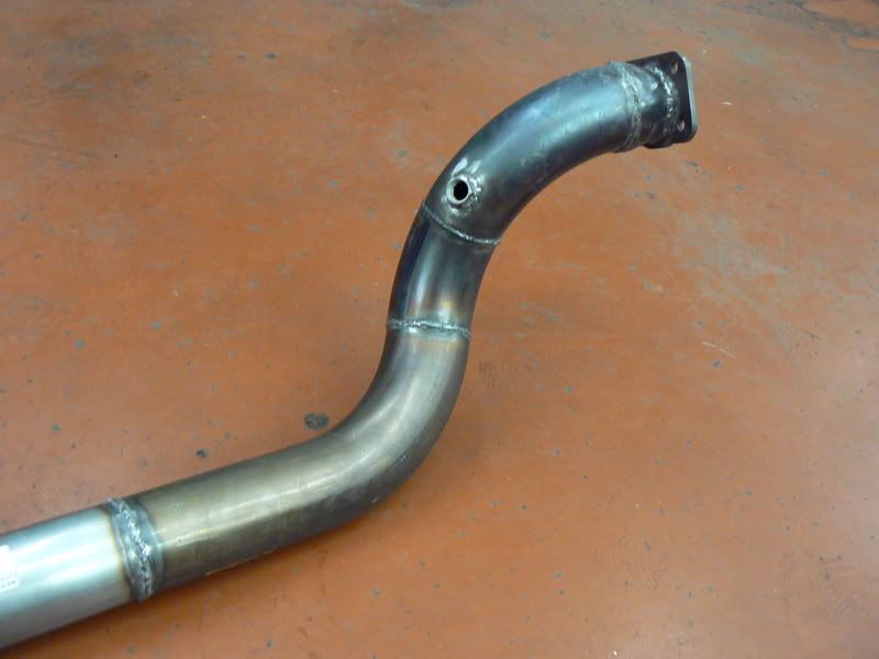
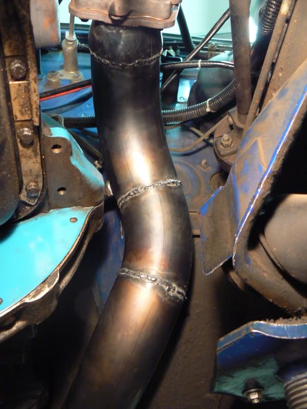
I've got one. 3" straight from the turbo, bolts up to a nissan T3, O2 sensor bung welded in, 6" radius mandrel bends. I would cut it off the exhaust shown in the pic where the color of the pipes change. $200 shipped.

-
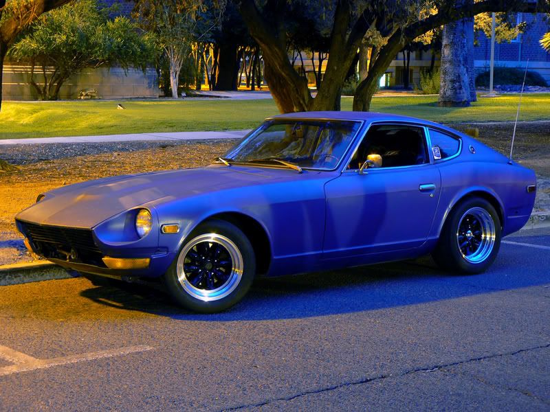
Satin-ish blue:
-
Love it.
I just bought a second 190 (this one an '89 2.6) to strip and turn into a DTM car. I can't wait.
-
The factory service manual has typos, too. Unless you think torquing your main caps to 3-4ft.lbs. is a good idea...
-
(over torque?)
Factory torque spec on the camshaft sprocket bolt is 86-116 ft.lbs. Turning the motor by it is fine. Just fyi.
-
Turbo or N/A oil pump: Turbo
Oil weight used: 20w-50
Synthetic or Natural: Synthetic
Oil Pressure at Idle when cold: 35psi
Oil Pressure at Idle when hot: 10psi
Highest oil pressure seen when cold (max RPM): 75psi (3000rpm)
Highest oil pressure seen when hot (max RPM): 65psi (7200rpm)
Turbo: Yes
Turbo oil restrictor size: .060"
This was on my old motor with new rod bearings but 200k miles on main bearings. New motor isn't broken in yet but numbers are looking to be similar.
What's the purpose of this thread?
-
I don't know the first thing about sport bikes, but I LOVE the huge brake rotor bolted to the wheel like that.
-
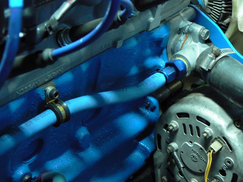
I'm no longer running a heater so I was able route the return line much nicer. It's still the same to the T, but now:
I've got right at 10,000 miles on the bypass ports right now. I have no proof that they've helped, but I do know they're not hurting a thing, I've found zero adverse effects from this.
-
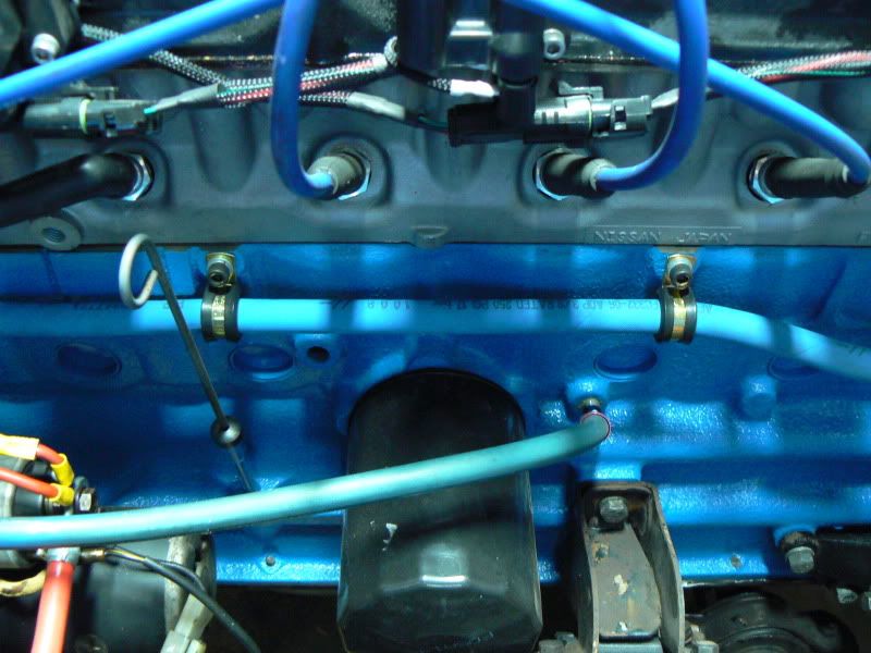
I've had the car running since Sunday night (10/18). I've got about 125 miles on the motor at the moment. Everything works perfectly. No oil/water/vacuum/exhaust leaks, and my crank trigger and coil packs are working absolutely beautifully (see here). My trigger angle guess was close, it came out to 84°.
So far zero interference issues with the shortened wires. The 4-puck disk is definitely a bit harder to drive with (grabs much more aggressively, chatters more), but totally livable, especially for a weekend car. I don't know if the chatter increase is affected by the fact that it's a solid center, but I can say that having a solid center hasn't changed shifting ease/difficulty AT ALL, it's no harder to make a smooth shift with the solid center than with the sprung center.
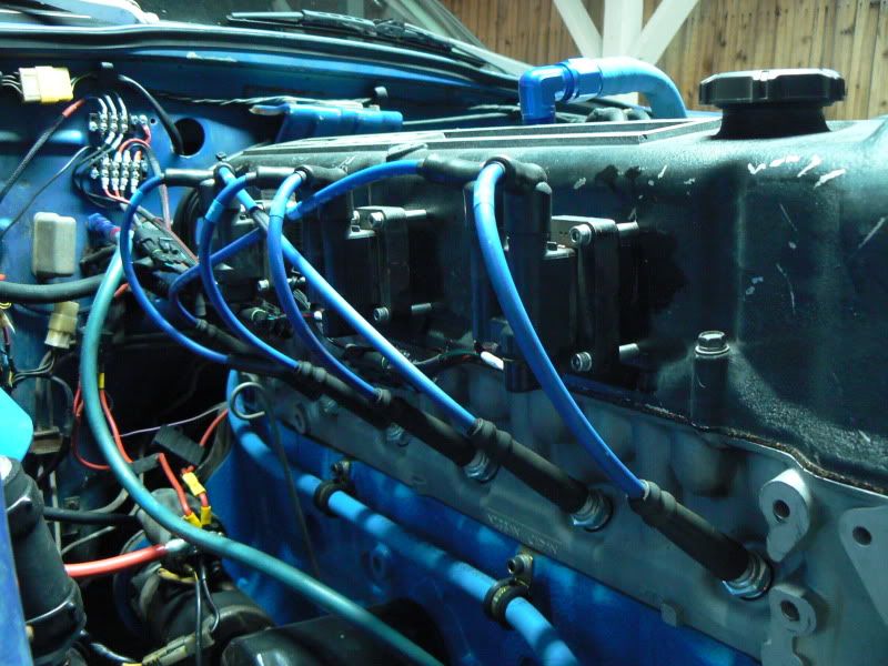
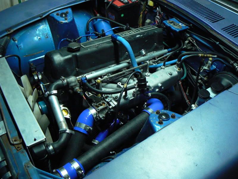
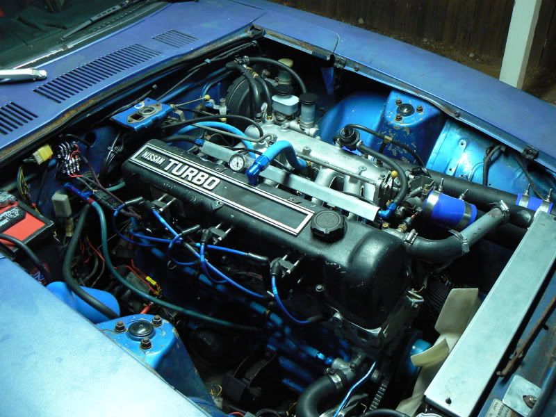
Some overall pics and such, since it's finished and clean:
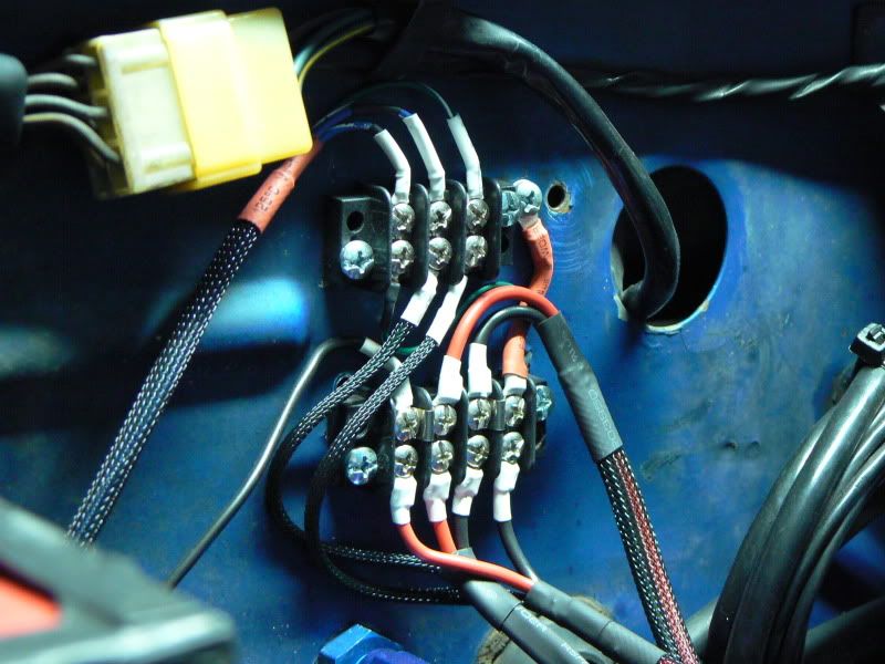
(Top block: Spark A, Spark B, Spark C) (Bottom block: left two are + (dinky black wire in top left is power from tach), right two are ground)
The -10 Aeroquip hose I'm using for the valve cover breather doesn't like making that sharp of a bend off a straight hose end, as you can see by the partial kink (I overestimated the distance it had to travel). I'll be getting a 45° hose end next time I place an order somewhere.
That ZX coolant inlet housing is 1/2" NPT, if anyone's wondering. Also, if anyone ever wants specific/close-up pics of anything on my car, feel free to PM me with your requests, I'd be more than happy to snap a few for you.
-
I like using Earl's 'Super Stock' AN hose ends with Aeroquip knurled push-on hose. The hose ends come with super-thin aluminum crimp collars to crimp the hose on the ends (though they're not required for use, the hoses will hold 250psi without weeping with no crimp collar). I'd like to make use of the crimp collars as I've been told it's good practice, but I make new lines so rarely I can't justify the huge expense for an actual hose crimper.
Does anyone know of any dies I can just use with my vice, and/or some way of crimping them myself for little cost?
-
Raising the bar a little
All I could think the whole time: "Oh man, the L vectors!!!"
-
I drilled a counterbalance hole, all should be sehr gut. See here.
-
Thanks for the compliments guys.
I was seriously considering using the ring gear teeth (120 count so it works) but in the end it came down to being easier to drill holes in the flywheel than to drill/tap a mounting hole in the bell housing of the tranny. Plus, this had to be done on a weekend for free, so machine shop work or extra tools beyond what I had were not options.
Looks like the demand for a write up is pretty high, so I'll make sure to document every single decision I made and every snag I hit. I have back-to-back exams tomorrow (I love college..) but it'll be written up this weekend for sure.
-
I can definitely do a thorough write-up on the install. It'd be from the perspective of already having MS in the car running fuel only, or any other type of spark. I'll even be able to show how to make it work with the 240Z current-sensing tach, since mine is working great so far (yes, my original '73 is current-sensing, though it does not suffer from the rising needle at high ambient temps that the earlier tachs do).
I've got about 85 miles on the motor so far and I've not had one tach spike, not one dropped spark, not one blip. Smooth as silk and dead consistent. Holding the motor at 3k rpm free rev, the crank pulley marks are rock solid under the timing light, no bounce I can see with my eye. There was a noticable +/- ~1.5° bounce in the dizzy set up (welded mech/vac advance, so it was all gear slop).
I cannot wait to see the difference under full boost above 5k rpm. The rest of my set-up is almost identical power-wise to what it was before so it should be a decent comparison.
-
But if you use your time not shifting to do your knitting...
-
I've been trying to find ITM pistons for the turbo all afternoon. Everybody is out of stock and ITM doesn't know if they'll be getting any more.
I just bought a new set of 86.5mm ITM cast L28et pistons off eBay not more than a month ago, for under $200. I would keep looking there, they pop up all the time.
-
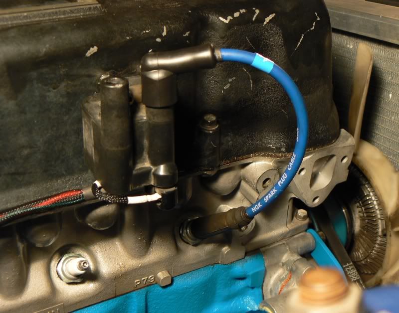
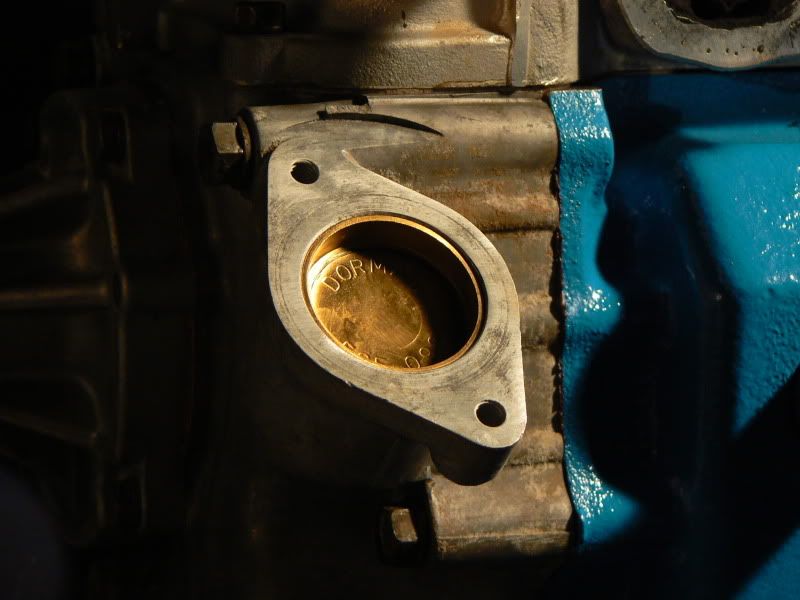
Thanks guys! I knew it would work in theory, but having it actually fire up and run is just the greatest feeling ever. I keep staring at the brass core plug in the timing cover while the engine's running, thinking, "Wow, there's no distributor there. And it's freaking running."
This was cheap, too. Somewhere around $125 for everything. Including shipping, the major components were:
Sensor ($35) - Digikey
Coil Packs ($48) - eBay
BIP373 x3 ($27) - DIYAutoTune
I thought one of the complaints of a low tooth count wheel was timing inaccuracies, any comments?No official comment yet since I only first fired up this new shortblock + ignition set up last night around midnight. While fine-tuning the trigger angle at idle it bounced around a tiny bit but not much at all, far less than my locked VR dizzy. I'll let you know what it does holding at 3krpm, and then once the motor's broken in, holding around 6.5krpm (probably videos of both, too).
Also, a trick I didn't show in my build thread was that I used the 4 IAC wires already in the DIYAutoTune harness. 3 for the coil outputs, one for +12v for the crank sensor. They have jumper pads right on the V3.0 board ready to go.
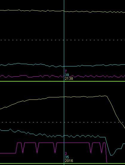
Edit: Here's a quick comparison with MegaLogViewer. VR dizzy rpm signal on top (in yellow), new crank trigger rpm signal on bottom (still yellow). Similar RPMs, same scale (0-2500rpm). The VR signal was at cruise on the road, the crank trigger signal was at a free rev, so I bet it'll be even more steady on the road.
-
Holy crap, my new distributorless ignition system freaking works. I'll update my build thread once I wash the engine bay, but for now I had to post something in all this excitement. There are soo many places for things to go wrong: bad crimps, crisscrossed wires, crank sensor not reading the holes in the flywheel, MegaSquirt not reading the sensor or pattern right, etc. etc. etc.
But it fired up and runs so smoothly. My set-up:
MSnS-E 029y4 code, MSI V3.0 board
Cherry GS100502 geartooth hall sensor
6-1 wheel pattern machined into flywheel
Stealth/3000GT coil packs
BIP373s bonded to the underside of the coil packs
Modified NGK plug wires
This thread has no technical purpose, just to share the joy of something I've been working on for a while (and had many failed attempts in the past) finally come together well.
-
A 35mm brass core plug makes the nicest dizzy block-off I've seen anyone else do, so obviously I followed suit.
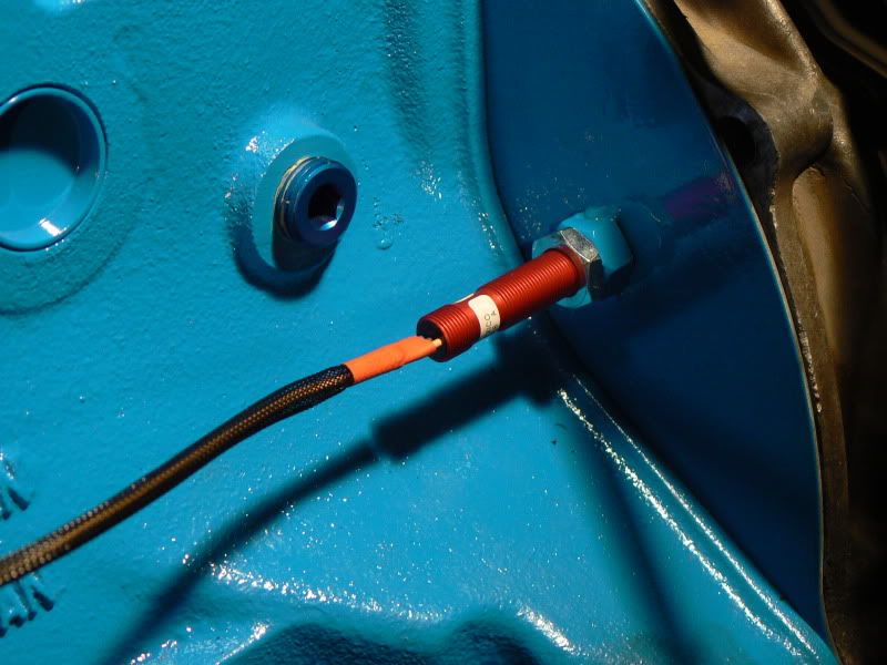
I screwed the sensor all the way in, then backed it out 1.25 turns for a 1.25mm (.050") air gap. This is definitely small enough, I just hope there's not enough run-out on the forward face of the flywheel for contact (I seriously doubt it).
I have really grown fond of the NGK spark plug wires I've been using. They're inexpensive, seem to be built well, and don't give me any interference problems with MS. Of course they'd have been a quite horrible fit for my coil packs as they were, but couple this Taylor dizzy terminal kit with a couple hours of swearing and some careful cutting, and now they're perfect.
The only two that touch are 2+6, but I added some heat shrink tubing there for some extra protection. I'm a bit worried to see how the amount of EMI changes with the changes in legnth (and therefore resistance). I think they were all somewhere in the 5.xk ohm range at original length. Now, the four shorter ones are ~1.8k ohms, and 2/6 are 2.7k/2.9k ohms, respectively.
A couple random things that don't have a specific place or pictures:
- I switched from a 6 puck sprung clutch disk to a 4 puck solid disk. It was noticeably lighter. I'm told by some that I won't notice much of a driveability difference between the two, and told by others that the 4 puck solid will be hell on the street. We'll see.
- I bought a Powerforce damper (the cheaper one) since the elastomer on my old stock one had seen better days. Just like everyone else's, mine mic'd a couple thousandths of interference. I just heated the bore of the damper up well and it eventually went on, though I had the advantage of having the engine on the stand so I could hit it squarely. It wasn't that big of a deal, and I feel more comfortable knowing it's on there solidly and isn't gonna damage the keyway moving around. So far, I'd buy one again, though hopefully I won't have to.
-
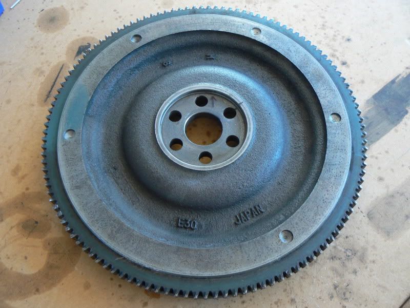
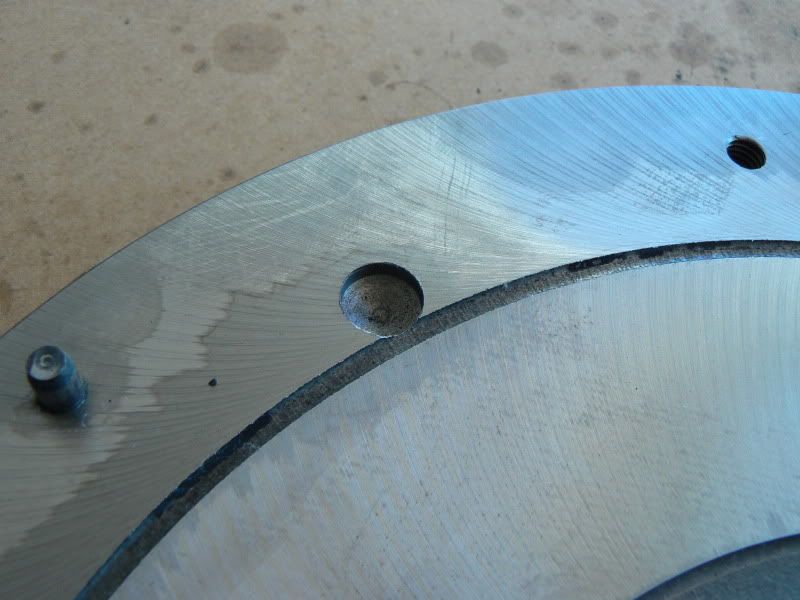
I finally decided on using a 6-1 pattern in the forward face of the flywheel, based on my specific needs (ease of sensor placement, accuracy, ease of machine work, etc). I did it myself with a friend's HF drill press; not all that hard to do if you just work slowly and carefully.
The arrow points up at TDC, and that tic mark on the 2 o'clock hole denotes the sensor's position (again, relative to when the motor is at TDC). Note that this will create a trigger angle of 90 degrees, give or take depending on exact sensor placement. It was easy to measure/mark precisely where the holes needed to be by using the fact that there are 120 teeth on the ring gear. Some careful work with a dial caliper and I was able to be sure the marks were right on the money. I made sure the hole depths were plus/minus .001" of eachother (to ensure the material removed from each hole was of equal weight), then drilled an identical hole (size, depth, radial position) where the 'missing tooth' would be, but on the opposite face of the flywheel, to keep it in balance while still providing the 6-1 pattern the computer needs.
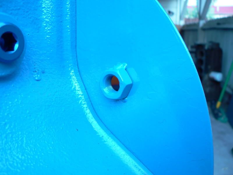
The sensor threads in to this super-fine-pitch (M12x1.0) nut tack-welded onto the engine backing plate.
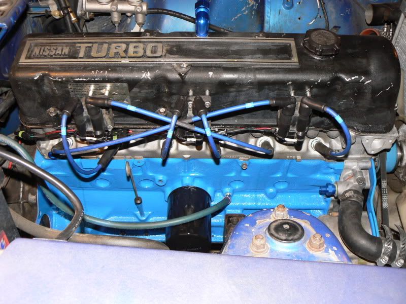
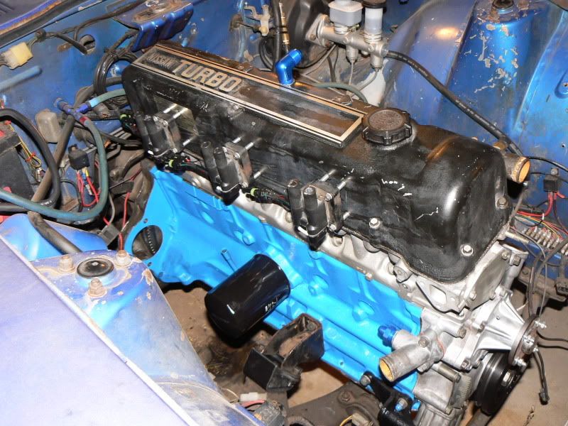
Also happened to get the engine back in the car. The flash on my camera is harsh, I swear my valve cover/engine bay isn't that dirty...
-
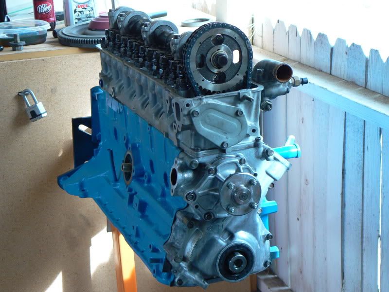
Engine mostly assembled
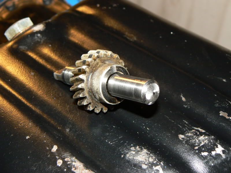
Since the dizzy drive end of the oil pump shaft is unsupported without the dizzy, I took a second to remove it. It was wonderful installing the oil pump + drive without having to give a thought to gear orientation.
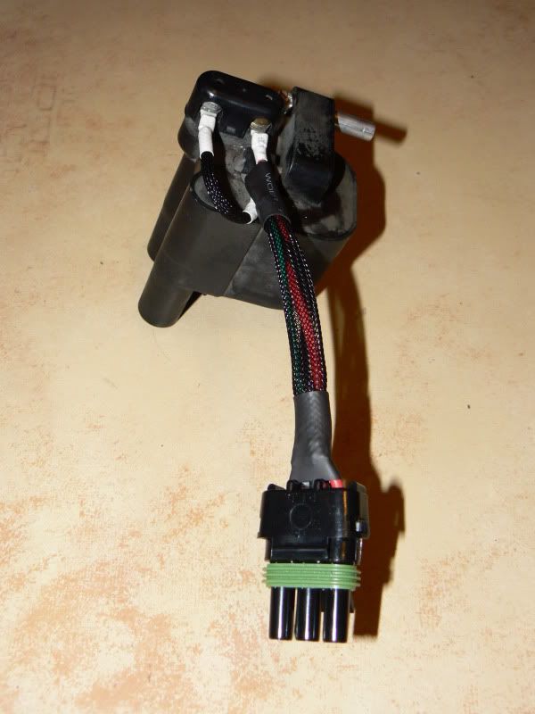
I'm using 3000gt coil packs, to the underside of which I have glued BIP373s. All wired up...
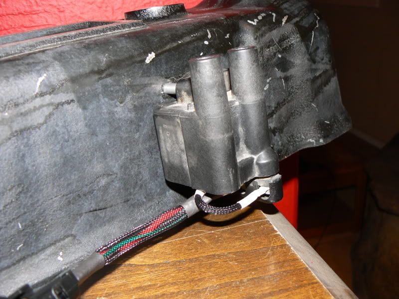
...and mounted to the valve cover
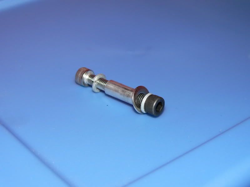
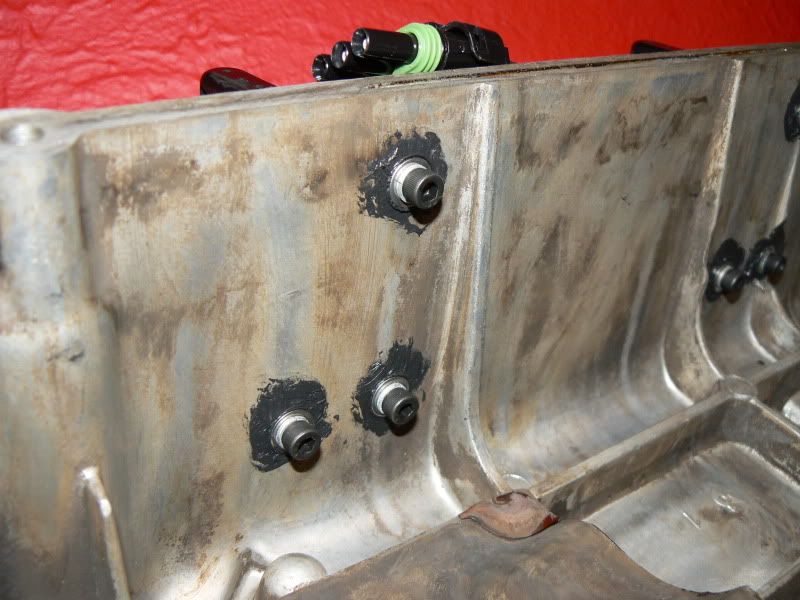
It's not apparent in the picture, but the aluminum stand-offs I used keep the coil pack around 2-3mm off the valve cover. Mounting hardware used:
I used some sealant on the back side of the holes to hopefully keep them from weeping, and threadlocker + split washers so they don't vibrate out and create mayhem.
Turbo Guys - Don't Give Up
in Non Tech Board
Posted · Edited by X64v
Thanks Dave. I definitely don't hate the turbo setup I'm getting rid of, I'll miss the power dearly. It was an absolute blast to run around town with and pass people at full boost driving up the one lane roads to Phoenix.
However, I do want to start hitting up more track days, and for sure make every autocross in the coming months. Being busy, poor, and in college, I need something that I can absolutely rail on time and time again without having to constantly worry about pinging, intercooler heat soak, fuel starvation, etc (most of which was probably my fault for trying to squeeze in every last degree of timing and pound of boost I could). I could have achieved that with my current setup, but at an even greater cost than what I've already sunk into the thing.
I've already taken 75lbs out of the car since getting a cushy daily driver, and I'm really looking forward to see how much weight I lose in turbo things. Another reason I'm doing this is having all this power has made me a lazy driver, especially at the autocross course. The higher I turned the boost, the slower my course times. I was forgetting to carry speed through the corner, instead concentrating on straightening the wheel as fast as possible so I could nail the throttle - definitely not the fastest way around the track. With a lighter, less torquey car, I'll be forced to use my driving to get around the track quickly, not my power.