
markrolston@mac.com
-
Posts
348 -
Joined
-
Last visited
-
Days Won
18
Content Type
Profiles
Forums
Blogs
Events
Gallery
Downloads
Store
Everything posted by markrolston@mac.com
-
Progress on my insane VQ35HR 240Z project
markrolston@mac.com replied to markrolston@mac.com's topic in Nissan V6 Forum
Plenum turning out harder than imagined. Regardless, still working on it. In the meantime, a few minor things: A shot of the Borg Warner 6758 (http://www.turbodriven.com/files/pdf/179388-EFRTechPages.pdf) that I plan to use. And a shot of one of the manifolds nearly done. -
Progress on my insane VQ35HR 240Z project
markrolston@mac.com replied to markrolston@mac.com's topic in Nissan V6 Forum
thanks. design constraints (hood) require I curve the runners in order to lay the plenums down on their sides. Horns will be mounted ~1/2" off the backing plate in the plenum. You can see the horn itself in some of the pics sitting free. Likely to switch to CF for the plenum since aluminum is turning out a PITA to shape the way I want it. Lastly, since this is estimated to be ~700hp turbocharged motor when done, the +/-5hp variable from minor design flaws isn't my concern. I'm just trying to trap major issues while at the same time keeping it an attractive design. -
Progress on my insane VQ35HR 240Z project
markrolston@mac.com replied to markrolston@mac.com's topic in Nissan V6 Forum
Thanks. So looking at what I'm creating, do you have particular suggestions? The fuel rail is in the stock location, towards the base of the runners. Air horns are inside the plenum for each runner. Tb's are stock. Mark -
Progress on my insane VQ35HR 240Z project
markrolston@mac.com replied to markrolston@mac.com's topic in Nissan V6 Forum
the suspension travel should still work without cutouts. The diffuser will mount to a crossmember in the front and to the body in the rear. We are looking for a muffler but given the shape and the 2-in, one-out, all on one side of the muffler, we'll likely just make our own. -
Progress on my insane VQ35HR 240Z project
markrolston@mac.com replied to markrolston@mac.com's topic in Nissan V6 Forum
early drawing of my diffuser and exhaust setup. This is generally how I first try and resolve packaging issues. In this instance, I'm trying to create a setup where the exhaust can be switched to free flow or quiet mode and where the diffuser runs under the rear suspension arms and works elegantly with the original body lines. I'm planning on making it with CF (duh) by creating a reverse mold in foam, smoothing it, and then laying CF. -
Progress on my insane VQ35HR 240Z project
markrolston@mac.com replied to markrolston@mac.com's topic in Nissan V6 Forum
further progress with the plenums. The design has taper for maintaining air velocity and volume uniformity, it has horns internally to optimize flow, and long runners for midrange torque. Otherwise, it's guesswork until we get dyno proof. If nothing else, it's a turbo motor so flow inefficiencies will be masked by FI and it'll look cool The plenum will taper to meet the throttle body at the front. mark -
Progress on my insane VQ35HR 240Z project
markrolston@mac.com replied to markrolston@mac.com's topic in Nissan V6 Forum
Dry sumps are amazing. You should read up on the tech- it's very cool. Basically, oil is stored outside the motor in an external tank, making the sump volume basically whatever I want. There's a good writeup on the original VQ35DE setup: https://www.fontananissanracing.com/Dry_Sump_Oil_Pan___Pump.html Also, check it out, the sump pump arrived. -
Progress on my insane VQ35HR 240Z project
markrolston@mac.com replied to markrolston@mac.com's topic in Nissan V6 Forum
There will be separate CF shroud from the nose to each of the coolers, the radiator fed from the area below the bumper and the IC fed from above the bumper. The air will be forced into the coolers. The exiting radiator air is dumped under the car, the IC exiting air exits out of the hood vents. Pretty simple. The reason they are tilted is to direct the air towards their exits and the pinch where they meet is a practical way of having the shrouding surface shared between the two cooling shrouds. What you suggest is possible but I have less capacity for that much air to exit from the hood. Some of it needs to exit under the car. -
Progress on my insane VQ35HR 240Z project
markrolston@mac.com replied to markrolston@mac.com's topic in Nissan V6 Forum
just got the dry sump pan in from Dailey Engineering. Wow wow wow. Sooo beautiful. Also a little design progress on the intercooler and intake plenum. -
beautiful work. I might have gone this direction had the timing been different. Are you making a CF dashboard? my compliments to your work and passion for the Z. mark http://www.rolston.me/NewSite/New_Z_Blog/New_Z_Blog.html
-
Progress on my insane VQ35HR 240Z project
markrolston@mac.com replied to markrolston@mac.com's topic in Nissan V6 Forum
we are working this week on the intake and turbo manifold as well as positioning for the intercooler and radiator. here are some pics of the mockup work. You can see a mockup radiator in place. The intercooler would sit above it angled forward. The Turbos are a Borg Warner 7064. At least that's what we think will work best. There is little data out there on these new turbos. Right now we're doing the fit work with a loaner. They fit neatly into the V-space to the sides of the motor. We will clock the turbine outlet to point upwards just in-between the frame tubes. It will then do a 90 turn and go straight into the intercooler. Should look nice. The turbos are very nicely designed. The WG, BOV, and boost control are all built into the unit. As you can see, we are just starting on the intake. The pipes you see will be cut down and terminate into a plenum on each side. One of the issues is visual symmetry. Since the banks on each side are offset, we're going to have the runners angle just a tiny bit so that they terminate within 1/2" on each side. The rest we can make up in the plenum. We're going to dramatically cut down the cam-covers since they are covered with all kinds of mounting tabs that we don't need. We'll end up remaking them as CF parts. -
Progress on my insane VQ35HR 240Z project
markrolston@mac.com replied to markrolston@mac.com's topic in Nissan V6 Forum
To get a new mold I'd have to fix the transition in my silver z and re cast that. Maybe one day but not now. If I were to cast the new car it would be a cast of a cast and would likely lose key line quality. Like a second gen zerox. You introduce noise and degradation. As for progress, we are working on the engine bay and will have most major elements in place by end of June. Brakes, intercooler, radiator, turbo plumbing, custom intake, and dry sump system all in the plan. After that it's diffuser design and fabrication, fuel lines, battery, diff and axle install, and wheel well fabrication. All that is hopeful by end of August. For the fall it's interior work, wiring, and other remaining stuff. Then off to paint by November or so. I want to get it on the track by spring 13'. Pics coming soon. -
s30 Fiberglass tilt front clip i've googled for hrs...
markrolston@mac.com replied to vega's topic in Body Kits & Paint
He really isn't in the business of Selling parts since he and I made the mold just for this car but you can ask him. His name is Al and he runs Al's Bodyworks in Austin. 512-836-1851. -
s30 Fiberglass tilt front clip i've googled for hrs...
markrolston@mac.com replied to vega's topic in Body Kits & Paint
Check out my solution. I made a mold of my front end. Fenders a flared though. http://www.rolston.me/NewSite/New_Z_Blog/Entries/2009/1/15_Front_Body_Mold_Finished.html http://www.rolston.me/NewSite/New_Z_Blog/Entries/2009/8/1_We_pulled_a_part!.html http://www.rolston.me/NewSite/New_Z_Blog/Entries/2012/3/5_Carbon_Fiber_Hood.html http://www.rolston.me/NewSite/New_Z_Blog/Entries/2012/4/15_Nismo_Fiesta.html Mark -
your question is not entirely clear, but I'm assuming you're wanting to know where the torque peaks: The chart starts at 2.25 and goes to 8k rpm. So the torque is peaking at about 6250 rpm. We cut off the run at 7500rpm.
-
655hp on c16, 505hp on pump gas. -street tune with 435hp, 378ft-lb torque -pump gas race tune with 505hp, 381ft-lb torque -c16 race tune with 510hp, 382ft-lb torque -c16 race tune with 24lb boost, 655hp, 493ft-lb torque http://www.rolston.me/NewSite/Z-Blog/Entries/2011/5/16_New_Tune.html
-
Progress on my insane VQ35HR 240Z project
markrolston@mac.com replied to markrolston@mac.com's topic in Nissan V6 Forum
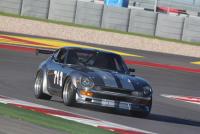
took the car to Nismo Fiesta last sunday. a few pics: -
Progress on my insane VQ35HR 240Z project
markrolston@mac.com replied to markrolston@mac.com's topic in Nissan V6 Forum
steel doors are safe. I want the car to be light, but safe enough to get hit in or roll. I expect there is another 400+ lbs to add: Turbos, IC, radiator, seats, dash, paint, fluids, electronics, glass, trim, etc. Still, est about ~2200lbs it's still going to be crazy light at ~700hp. mark -
Progress on my insane VQ35HR 240Z project
markrolston@mac.com replied to markrolston@mac.com's topic in Nissan V6 Forum
hood works now. side panels are cut off and will get mounted to the frame. Engine bay is starting to look really cool. Also, rear body under the bumper is cut out for the eventual diffuser. i'm going to try and shape a mold for that with foam this week. Car weighs 1700lbs right now. We lost the specific component weights in the move (Andris moved into a new building). We hope to find it as we unpack. I'm taking the car to a Nismo show in San Antonio this sunday. Should get lots of nice pics. -
Progress on my insane VQ35HR 240Z project
markrolston@mac.com replied to markrolston@mac.com's topic in Nissan V6 Forum
ha! I wish. That's just the rust-prevention coating. it gets burned off the first time the brakes are used. -
Progress on my insane VQ35HR 240Z project
markrolston@mac.com replied to markrolston@mac.com's topic in Nissan V6 Forum
It goes something like this (pics)... cover the clay with CF. remove the clay underneath, fill in behind, create a part line. -
Progress on my insane VQ35HR 240Z project
markrolston@mac.com replied to markrolston@mac.com's topic in Nissan V6 Forum
fender transition is done. Looks good to me. now to cover it with CF and remove the clay foundation. also, moved my entire personal website this week since Apple is shutting down their MobileMe website hosting. PITA. The new location is www.rolston.me -
Progress on my insane VQ35HR 240Z project
markrolston@mac.com replied to markrolston@mac.com's topic in Nissan V6 Forum
right. it's not yet smooth. The curve is kinked in a few areas. We are still working on it. We have to go so far up the arch because the original arch flares outward along the X axis (x being side-side dimension of the car) and not just an arch on the Y/Z axis. So the cut is high up to create a smooth transition not just Y/Z, but also X. The photo is somewhat misleading since you can only really perceive Y/Z. And the clay is just for modelling. It won't be there in the final part. mark -
Progress on my insane VQ35HR 240Z project
markrolston@mac.com replied to markrolston@mac.com's topic in Nissan V6 Forum
kinda. it's a hack. not the best way but it's a small part so it'll work. -
Progress on my insane VQ35HR 240Z project
markrolston@mac.com replied to markrolston@mac.com's topic in Nissan V6 Forum
working this week to get the car assembled. Right now we're trying to resolve the ugly pinched line that is created by the transition from the wide fenders to the stock-width airdam. We are using automotive clay to resolve the shape and then we'll do a thin layer of CF and bond it to the original part. As you can see, we are still working to resolve the shape.