
MONZTER
-
Posts
818 -
Joined
-
Last visited
-
Days Won
17
Content Type
Profiles
Forums
Blogs
Events
Gallery
Downloads
Store
Posts posted by MONZTER
-
-
Does anyone have the EXACT part number for the Bilstein gland nut? I got some here, they are B30-629 Q1 and they are about 2mm too big. Might be the right one for a 280 strut, but they definitely don't fit a 240...
Jon,
Here is my info -
Strut part number - F4-P30-0032-MO re-valved 300/100
Gland nut part number - B4-B30-U232A1 M48x1.5 OST - this is what the invoice said
I was told the nuts people use to use are no longer available. I went back and forward with Bilstein a few times to figure this out. These work but have to be cut down in length. Check out the pictures below.
ps I would highly suggest getting the tool to tighten them
Jeff

number on part says B30-629 and A1
-
Thanks for that link Alan. Those parts look so good. The doors are amazing. These are the type of parts I have been looking for. Now if I could only find a way to get some of them over here?
It’s scary how much you know about these cars.
Jeff
-
First and Foremost! Don't thank me, thank Jeff, Tony and Super Dan! They have help us more than you can imagine!!!!!!!!!!!!!!!!!!!!
Kevin
I also don’t want anyone to forget Mike (TurboBlueStreak)
He is the computer genius who started this hole CFD testing process. He taught me how to do it and I thank him. He was also responsible for all of the first test, as well as Ron’s test. He is currently working on some really good stuff.
-
Jeff, if the HKS Type 2 was to have a series of holes bored in the wall separating the upper plenum from the lower plenum, what kind of flow icrease/improvement would there be?
Reason I'm asking is the Type 2 will be going on those HKS ITB's, and I really have no need for the restriction in the upper plenum...but would like a better flowing 'period correct' looking piece when I install it on my 73.
I'm thinking I can access the wall with a drill bit through the carb openings, and then enlarge the holes by hand with a right angle die grinder.
Yes, I could use the Type 1 in the application, but the Type 2 is what HKS was hawking for the ITB's when they came out.
Thanks!
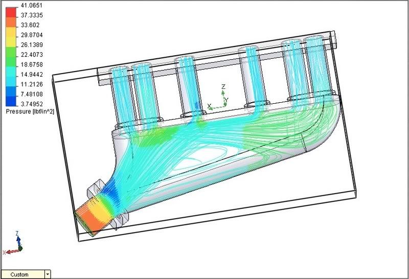
Hi Tony, I did the mods you requested, and it appears as I thought, the restriction is not between the upper and lower plenum and not really the problem. Here is what I did -
1.) Standard HKS Type 2 - flowed 442CFM at 25"
2.) Standard HKS Type 2 - Same test but without the bolt on inlet, just straight into the two openings on the plenum - 640CFM at 25"
3.) Standard HKS Type 2 - same test but opened up the outlet from the bolt on inlet as big as possible between it and the plenum - 582CFm at 25"
4.) I also tested it with the same as above, but with 1 inch holes in 4 places between the upper and lower plenum like you suggested - no real difference, just the flow into the runners did not seem as even. Pictures below are of this test. As a side note - with the above changes the pressure drop went way down as well.
My opinion would be to leave the plenum alone and work on the bolt on inlet. Currently the inlet is only 60mm inlet where the others I have been testing are at 70mm. (Rons flowed a huge 844CFM and mine is at 650CFM both at 25â€) There is a lot of thick walls in the inlet and some serious porting really seems like it would help without messing up the nice even flow.
I hope this helps
Jeff
As usual, click the pics to enlarge
-
When I first saw them I thought they were these
http://forums.hybridz.org/showthread.php?t=129095
This was a post a while ago, about some wide flares that sold on E-bay. I believe they were special 432-R flares. The bolt holes look different on yours. I wonder if Alan (HS30-H) has any info about what they really are?
Jeff
-
I use a Tec3R with an AIC solenoid. I turn the car on, wait for the fuel pump to run for a second or two then turn the key and it starts. The AIC opens a programmed amount for startup and then closes a little to keep the idle at 1200 until warm. Works great. The better part of the AIC is after blipping the throttle. It acts like a dashpot to keep the car from dropping the RPMs too fast and stalling with a very light flywheel. Electromotive makes a billet remote block for mounting an AIC valve really easy.
-
I have never had a problem. Been running them for years. Set up on the Z-head rocker wipe pattern is very critical. If you get it wrong, good-bye cam. I wonder if people blame the cam for their poor set-up, or lack of understanding?
-
Jeff, if the HKS Type 2 was to have a series of holes bored in the wall separating the upper plenum from the lower plenum, what kind of flow icrease/improvement would there be?
Reason I'm asking is the Type 2 will be going on those HKS ITB's, and I really have no need for the restriction in the upper plenum...but would like a better flowing 'period correct' looking piece when I install it on my 73.
I'm thinking I can access the wall with a drill bit through the carb openings, and then enlarge the holes by hand with a right angle die grinder.
Yes, I could use the Type 1 in the application, but the Type 2 is what HKS was hawking for the ITB's when they came out.
Thanks!
Tony,
I'll add some holes in the divider floor, but I dont think that is the only restriction point. I think it may also be between the seperate elbow part and the main plenum (lots of room for enlargement). I will do a little work to figure it out for you.
Jeff
-
Just a little update.
Been working non stop on the design trying to get it perfect. I have the flow really balanced out nicely between all runners. Now I am just looking at pressure drop, and total flow. I should be posting some final results of this design as well as all the other designs tested in my research. As far as making a quantity of these! It was never my intention to make any more than 1 for myself, but provide the information to the group to use it in the creation of their own designs. I am not really into the idea of using the forum as a sales tool as much as I am into it as a fantastic knowledge base.
-
I have been running the Bilsteins for about a year now, re-valved 300-100. I keep having a problem with the gland nuts loosing up. I locktited them this time, I hope I can get them apart someday? Anybody else have a problem with them coming loose?
-
It does sound like the correct center section, I just have no idea how the standard size wheel will react with the smaller A/R compressor housing. You would need to see a compressor map for that combo, as the standard map for the stock .7 A/R will no longer be accurate. Who knows it might be really good, but then, why doesnt Garrett offer it that way?
-
I'm the guy in yellow.
Somewhere in France
Bikes: Trek 5500 DuraAce, Titus Racer X, Guerciotti: restored (Steel is Real)
You Wish!!
:D -
I know this thread is about who rides to work, but I would like to see some pictures of your bikes. Lets see those Hybrid rides. I know a lot of commuters and their bikes are usually pretty custom for these specific purposes.
-
It looks like a GT 35r with a T40e compressor housing on it. You will have to pull of the turbine and compressor housings and measure the inducer and exducer size to figure out if the wheels are 35r specs. It’s hard to tell from the pictures, but the turbine housing looks like a 35r. FYI my GT30r has a ported 4" inlet and a 2' outlet on the compressor. My 35r has a 4" inlet and a 2.5" outlet on the compressor.
-
Me and a group from the office ride during our lunch break 3x a week. It is a full on beat each other up sprint for an hour. Well usually cover 17-19 miles. Its great for stress releif, and fun to talk @#&* on each other out on the road:razz: The technology in the bike business is simply getting crazy
-
I have bought a GT 35r .82 with hopes of making 500 hp to the wheels on a completely built engine and system. I do not believe a 30r is capable of 500 hp to the wheels on our old 2 valve type motor. If you goal is 400hp and better response then I think the GT30 will be great (but I would want it with the Garrett ported compressor housing, and high nickel turbine housing) if I paid for it. That’s just my opinion
-
I believe Garrett sell the bearing cartridge by itself. The compressor and turbine housings can be purchased separately. I believe people use the Garrett cartridge and then buy a cheap non Garrett compressor and turbine housing. By cheap I mean less expensive as the Garrett stuff is pretty expensive, but I also believe the turbine housings are made of a better material. What did you pay for it? If you paid full GT35R pricing then I would be bummed, but if you got a great deal on it, then that’s probably how. I was just shopping for the same turbo and all of the E-bay 35r's I saw did not have true Garrett housings, hence the good price. Check ATP Turbo. They sell them both ways; usually they only sell the non-Garrett housings for special fitting problems.
-
MONZTER those look great - I did not know you could get panasports in 16x8. I assume you have coilovers for the +19 offset. What size spring so you run? 8" or 10"?
You cant. Sal at Motorsport Auto ordered 2 custom sets from Japan. One for me and one for his 280. I am running 8" springs in the back with coilovers. The perches just fit above the tire so I actually can fit some 265 Kumos under there as well, its really tight.
-
Panasport 16x8 19mm offset 245-45-16 Hoosiers
-
Ron asked if I would run a test on his revised plenum. I thought it would be interesting to compare his revised design with his old design. I also thought it would be interesting to compare this single throttle open plenum design to what I am trying to do, as well as the HKS. Here is a link to Rons old results and pictures below of his new design
http://forums.hybridz.org/showthread.php?t=117607
Picture of his old design
Some pictures of his new design - 5 psi
20 psi
As usual, click on the picture for a bigger view.
Looking for comments, and yes Ron gave me permission to post his results, thanks Ron:D
-
How would it work if instead of the air coming in from the bottom it came in looking directly into the intake? The velocity of the air would add to the intake pressure and should increase the charge to the cylinder.
Now after your modeling of the 4x4 box, I think I am going to add a diffuser pipe down the center of it with a 1-1/2" hole looking at each carb throat.
I too vote for this post to become a sticky.
I don’t know what you mean about the air coming directly into the intake? Part of the design of the air going into the bottom is that it works with the cone to distribute the air evenly. Typically as velocity goes up, pressure drops.
-
now thats looking better, and the pressure drop is much lower than the HKS. getting closer
-
So I took Monday and Tuesday off and took the family to Palm Springs. We stopped at the WWII airplane museum. Some really beautiful stuff in there. Anyway, I was checking out all of the intakes and air scoops on the planes. One thing they all had in common was the inlets for the radiators. All of them had a deep honeycomb "grill" that acted as flow straightners to the turbulent air. Hmm this gives me an idea.
Jeff
-
Here are some shots of a standard 4x4x24 box with a 70mm inlet. Same 20psi boost at 793 cfm. Just as expected runner #1 not looking so good.
Again, click on the picture for a bigger view:


The Strut thread - Koni / Illumina / Tokico / Carrera / Bilstein / Ground Control
in Brakes, Wheels, Suspension and Chassis
Posted
So your saying the part number for one that does not need to be modified to fit a 240 is B30-629 A1
Let us know if you get them, as I would like to order some new ones after messing mine up for not using the correct tool to tighten them:biggrin: