

MONZTER
-
Posts
818 -
Joined
-
Last visited
-
Days Won
17
Content Type
Profiles
Forums
Blogs
Events
Gallery
Downloads
Store
Posts posted by MONZTER
-
-
Wow, thanks for the comments, much appreciated. I have not finished the front dif mount yet. I am waiting to finish my 3" exhaust routing, and then will build the mount around that. I think somebody else around hear built a mount using the mounting holes for the diff strap. Looks like a good idea, I will probably do something like that.
Jeff
-
Tim, I can cut up more of the head, but it looks as if the "flash web" runs the length of it. I would say it is a casting error. You can really see the difference in the quality of the casting between a N-42 and the P-90. On the outside near the port openings a N-42 is very nice and smooth. On a P-90 that same area is very inconsistent and rough. I wonder if this reflects on the inside.
Tony D, it looks like you could access some of the flash through some of the openings in the gasket surface, and also by removing the plugs in the rocker valley.
Sorry I cant cut up the N-42, its in great shape and going to be used on one of my projects. I did compare the water ports on the P-90 and the N-42 and they were the same. I think it was the E-31 that was different.
Jeff
-
Hey Guys,
Here are the pics of the cut-up P-90 showing the inside water passages.
The first two pictures show the inlet points in the gasket surface. You will notice that there are holes in the head that are blocked off by the HKS steel gasket. These could flow water if the gasket was opened up. In the second picture you will see holes in the head gasket that do not have holes going into the head. This makes me wonder if this was for a reason, or just a manufacturing convenience, so that 1 head gasket design would fit many application of the different years. I wonder if an improvement could be had by opening the gasket up to the holes in the head, and the head up to the gasket. Hmmm.
The other pictures show a large casting flash rib blocking probably 50% of the water passage from the bottom of the head to the top. This web was going from the #6 to the #5 cylinder. It appears that these flash webs are through the whole head. There are also some large casting bumps from the exhaust studs that would appear to restrict flow.
The final pics show the nice open cavity that flows above the exhaust ports. We talked about taping into the head above the exhaust ports, this looks like an ideal place.
Sorry about the big pics, but wanted to show the details. Click the pics to enlarge them from my gallery
Enjoy, Jeff

-
Then again...like GM found out in the 50's, but didn't take the $$$ to implement till the recent SBC Generation...who says the coolat needs to enter the block? Kind of stupid, no? Putting the coldest water in the coolest portion of the block---totally opposite of any other heat exchanger!
I reverse flowed a 6.6 Pontiac a long time ago, after reading some articles about it, and having it make sense to me: Coolest Water entering the hottest portion of the engine, and then pulling that heat down to the block where it aids in keeping cylinders round from equal heat top to bottom... Really cools down the heads as well.
I just cause all sorts of problems making statements like this, huh? LOL
I was waiting for someone to bring this up, Tony the trouble maker HAHAH. Now there is even more to think about...
-
the radiator is made by a company called Meziere http://www.meziere.com/index.php?pgName=rad
Interesting idea about tapping only one of the cylinders above the exhaust port Tim. I will take some pictures tomorrow of a cross sectioned head at #5.
Have you ever noticed that the cooling inlet size and hole positions on the head where it mates to the block has changed over the years. Some holes have been added and some omitted as well as there size. It would be interesting to check the differences between your N-42 and a P-90. I have both of those heads at work, I will check it out as well, maybe Nissan found the same thing out when they went to the P-90 head from the N-42.
I was also thinking about the flow. You know how they say on an intercooler with the inlet and the outlet on the same side causes a recirculation of the air inside the intercooler, and that baffling helps this. I wonder if the water could be seeing this same type of effect. Here is a really bad illustration of what I am talking about. On the left is what it should probably work like and on the left is a possibility of what could be happening?
Now if we only had a clear plastic head and block to watch the water flow:
-
I have a set of AZC front arms, and they did indeed bind when topped out. This was 5 years ago and I think there design has changed. I ended up cutting off the straight front tube, and adding a bent one to fix the angle. I then decided just to build my own.
-
When the car is on a jack and the front struts are fully extended, are you worried about the tie rod/ball joint binding? It looks like the center of the joint is perpendicular to the centerline of the arm. I wonder if the joint has as much rotation as the stock ball joint. Hopefully it's all good. Looks real nice, and easy to adjust.
I had to put a small bend in the front tube on mine so that the heim joint was in the middle of its range at ride height. This made it so no binding under full extension or compression. You can see the bend and angle in the front view on the picture below:
-
Hey Monster,
What is that brake setup on your car, sizes and who's kit?? Looks good.
The brakes on my car are AP aluminum 4 piston post mount in front with 13" AP cross drilled rotors. I designed the rotor hat and mounting bracket for the post mount setup myself. Everything is CNC machined from 7075 and hard anodized. I only made 1 set.
The backs are AP 2 piston post mount (same as a lotus Elise front) The rear rotors are cross drilled Z-32 rotors and the backing plate is also custom designed to bolt on and use all of the parking brake hardware from the Z-32. Again only 1 set.
Thanks Jeff
-
Thanks for the replies, I just did not know if I broke some un-said golden rule or not. I did pay for the work and I do own the head. Dave never even hinted at "Don’t show this or hide this" Like I said, he was super nice, prompt, professional, and on time. I just did not want to “burn any bridges†if there was some un-said rule I broke, I would defiantly like to use him again. Thanks Jeff
-
Thankee. Rebello might not like it, but *I* sure appreciate getting to see those shots of the combustion chambers.
Do you really think that was bad of me to post those pics? I dont want to piss anyone off, Dave seems like a great guy, and I did not realize that he might not want that sort of thing shown. I'm feeling kinda stupid now:bonk:
-
I cut in half a bunch of heads lately to investigate various ideas. One idea is just what you mentioned. Directly above each exhaust port is a nice open area that you could pull the water out from. I believe the water first has to flow past all 6 pistons before moving up and across the head for #5 and #6.
I am thinking about using a radiator bulkhead mounted water pump with 2 outlets. One outlet would go to the current front cover/front of the block. The second outlet would go around the block to the block drain lug under #6 so cooled water is going to the back as well as the front. Now if you tapped into the head above the exhaust ports and let the water flow out, it would eliminate the water having to pass over so many areas. Some of the problems I see are that you would have to block off the head bypass since the water is now being pushed instead of pulled. you will also have to block off the water pump opening. You would also have to plumb only cylinders #2-#6 leaving #1 as the current thermostat housing where the other 5 would collect and then go back to the radiator. #1 and the thermo housing is also a high point in the system so trapped air should not be a problem.
Here are some pics of the water pump, old nissan designs, as well as a manifold design I am working on
-
QUOTE OF THE DAY!!!!
EDIT
While I'm at it: Monzter, what head casting is that, P series?
It's a P-90
-
IMS - Industrial Metal supply in Irvine
-
Hi Braap,
Why on the intake only? That’s the only way I found them. I got them from the Kameari guys in Japan, and that was the only way they sold them. I did not know where else to get them except by going custom. Maybe some other application would have fit, but I had no clue where to find this info.
I was thinking it was because of a durability thing with the exhaust valve? and the hardness of the seat material? - just a guess. The head was done by Rebello. Dave got the head flow 212 at 25" .5 lift intake and 150 at 25" .5 exhaust. He said he spent way more time on the exhaust than the intakes. I'm hoping it will run pretty good.
Jeff
-
-
For me I think the biggest improvement isn't totally from the manifold, but by going stand alone fuel injection with a MAP based system opposed to a MAF system. This is what let me get rid of all the extra stuff and make the HP increase.
-
Hey Tim,
Got some Oversized Beryllium seats from Kameari directly. They are supposed to help transfer the heat better. Just had them installed, but not run em yet. I also got the Beryllium guides to help again to pull the heat out of the valves. Not cheap stuff, but I figured good insurance.
-
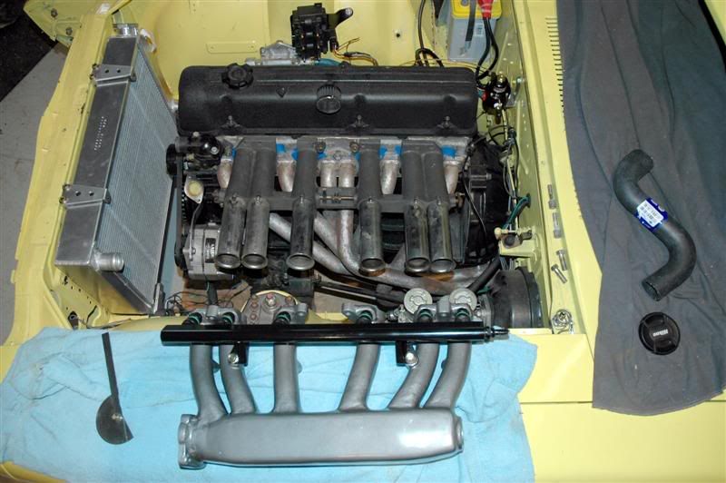
Nice MFI runners, Thats cool. ever run across any pics of the Lucas flat slides on a Z. Oh waite stop dreaming this is about a stock intake:bonk:]
Whats all those wire and hoses, just pull it all off, we did...
-
What about the one MSA Sells? I think there was a discussion not too long ago about this single groove damper.
-
Hey Braap,
Makes sense about the cooling, so why would anybody want to close them off at any level? I know they talk about it in the "how to modify book" Is it because of the extra windage? or maybe the high RPM loss of oil in the rod bearings? Hmmm
Thanks Jeff
-
So, on a L-28 turbo build with 1973 240 rods, should I close off the oil squirter hole in the rod or leave it open??? Does anybody know what the pros and cons are??
Thanks Jeff
-
John,
Thanks,
Good solution cutting off the threads on the old tie rods and building them into the new ones. I really like all the interesting ways people find to do the same thing so many different ways on this forum. Great option for people without access to a lathe; where did you find the swaged tubes? I remember seeing them once somewhere, but could never find them again. What is the wall thickness and material spec for those tubes?
Thanks Jeff
-
Yes I know what you mean about the bar hitting the tie rod. Keeping the bar close to the frame rails helps with this, but your idea for a different tie rod is perfect. I built some straight tie rods from 4340 with heim joints on the end to adjust for bump steer, as well as give more clearance on lowered cars. Have not tried them yet.
The tricky part about making the tie rods was the fact that one of the inner tie rods uses an m14x1.5 left hand thread. I found that if you call McMaster Carr they can custom make any tap you want for a reasonable price.
-


Understanding tuning of Electromotives TEC
in Electromotive
Posted
I don’t think that’s quite correct, as the TOG and the IOT work together. If you dial in the TOG and then change the IOT the curve will move down or up requiring you to modify the TOG again. It is a balancing act to get the car to idle correctly and do a full throttle pull. Once you get this worked out it time for the VE correction. I recommend lots of reading: Check out this manual http://www.directignition.com/pdf_files/tec3r.pdf
look at pages 61 down it has a good explanation of what you are trying to do.
Here is another good source of info http://www.thenewspaper.com/auto/info/tecfaq.htm it is about the Tec II, but still really the same. It is in a forum format so it is a little more real world.