
Dragonfly
-
Posts
674 -
Joined
-
Last visited
-
Days Won
1
Content Type
Profiles
Forums
Blogs
Events
Gallery
Downloads
Store
Posts posted by Dragonfly
-
-
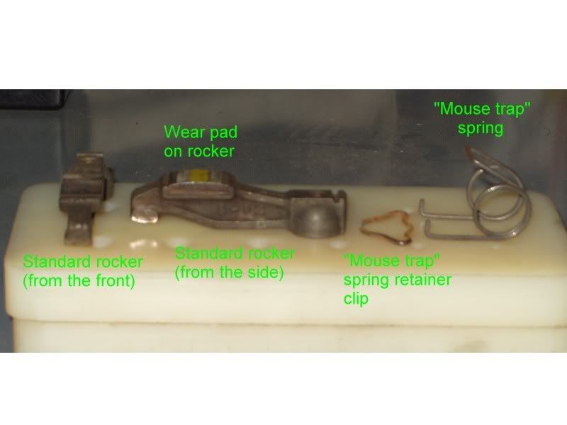
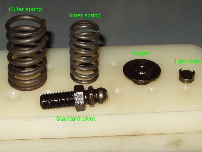
I am going to guess that you are talking about the mouse trap spring shown in this photo

and not not a valve spring like the ones shown in this photo.
If I am correct you will be perfectly fine in going to a wrecking yard and getting one, but if it is a valve spring youv'e got some work ahead of you.
Dragonfly
-
I hope that I do not cause additional confusion with this but... the primary function of a relay is to allow you to to use a low load source to complete a high load circuit. A good and common example of that is using a relay for your headlights, if you look at the drawing that vashonz shows you can see how to connect a wire from your battery to your headlights, when the relay is off (no power from the switch to blade 86) you have an open circuit in the relay and no electricity can flow, when the switch is turned on power will flow through the coil between blade 86 and blade 85 causing the contacts between blade 30 and blade 87 to close and your headlights to come on with current directly from the battery. What you have done in this excercise is used a very low current load through blades 85 and 86 to connect a path for a high current load between blades 30 and 87. This allows you to use less heavy gage wire and switches in your car and reduces the likely hood of melting wires by overloading them when you put in a 30 amp fuse instead of a 10 amp fuse (not saying you are going to do that but I see it all the time and everyone knows someone who has done that).
Dragonfly
-
Well Mike I have little doubt that you have been behind the wheel of all the cars that you mentioned and you are just looking for some opinions to help with your decision... well my opinion is to go with the GT2 with the intention of putting most if its milage on a track.
Dragonfly
-
This write up will explain it better than I can http://www.zraceproducts.com/damperinformation.htm like anything else out there it is a case of what you want to achieve and how much you are willing to spend to achieve it.
At this time I have not run one on my car but there will be one on my stroker before it goes back on the road.
Dragonfly
-
For those of you who want to have the best IMHO rather than the least expensive take a look here http://store.zraceproducts.com/enginecomp.htm this one is for a 350Z but he also has them for L series engines as well.
Dragonfly
-
I tend to overkill things when I do them but here is what I did with my cam (and I knew the specs already). Pull the valve cover, pull all the spark plugs, attach a degree wheel then using a 1 inch travel dial indicator, set it up with a magnetic holder and necesary attachments so you have all but one revolution aplied to the dial indicator with the plunger sitting on the valve spring retainer for the intake on #1 cylinder. Now that the setup is done rotate the crank 5 degrees according to the degree wheel, on a piece of paper write down the degree on the wheel and the reading on the dial indicator then rotate the crank 5 degrees again etc, etc untill you have completed 360 degrees of rotation (alot of which will read 0 inches of lift). After you are done with the intake repeat the entire process on the exhaust valve for #1 cylinder.
Now that you have a couple pages of numbers use either a computer program such as AutoCAD or a piece of graph paper and create a plot of each valve that you took numbers from. The plot will look like two arches that have an overlap in the center, this will give you a graphic representation of your cam profile WITH your rocker ratio and you will know exactly what your true lift, duration and overlap are for your cam. BTW set aside some time to do this it's going to take awhile.
Dragonfly
-
Well Jon, while your at it... you could make the set back plates like you had considered and then bolt an engine plate to the back of the engine between the engine and the transmission (like what Terry (blueovalz) has in his car). With that you will make all your mounting much more rigid and you will distribute the load from the engine and transmission across the tans tunnel, the frame rails and the modified engine mounts. Do some reading up on Terry's set up before you decide to take a bite out of this kind of project though.
Dragonfly
-
I then added weight while I ran stairs...I eventually got to 33 pounds (about 4.5-ish gallons of water bottles in a US military-spec backpack) and did 2500 stairs in 50 minutes...I did 3200 stairs in 35ish minutes with 20 pounds a few days later. I sure got a bunch of looks from the other students at school running the 5 stories in the dorm building.
I became "The Backpack Man" lol
I could really feel the muscles in my back that support my spine getting stronger. I also lost some gut I had goten lazy on (freshman 15 not good for a back either)
Then I broke my jaw so I have been sitting around quite a bit for the last two months...
I'll be back to running stairs and stuff in a few weeks.
My presonal recomendation is that you put the weight around your waist when running the stairs rather than on your back, that way you will only blow out your knees and not your back and knees. The best thing for you to do in reality is to go to a gym and find a machine that simulates the stairs without the impact on the knees then put the weight on your hips and go for it. As for strengthining your back follow the tried and true excercises that are known to build strength and/or mass without causing strain such as behind the head pulldowns, behind the head pull ups (like a chin up but you touch the back of your neck to the bar), seated rows and any of the other back excercises where your body is supported and your back "muscles" do the work. And as you pointed out already any physical therapy excercises do great.
For anyone who has never thought about this here is something to keep in mind: The formula for torque is force X lengh = torque where force is the weight applied i.e. pounds, and length is the distance from the weight to the point of rotation. Now with that in mind have someone help you measure from your lower back to your shoulders (length in inches) then weigh yourself, subtract 1/3rd of your weight and the amount left over is weight in pounds, now multiply the length by the weight and you have inch/pounds, take that number and divide it by 12 and you now have foot pounds. Here is an example: My height from my lower back to my shoulders is 26" and 2/3rds of my weight is 113 lbs that gives me 2938 in/lbs divide that by 12 and it gives me 244.8 ft/lbs. That is the amount of torque applied to my lower back if I bend straight over and touch my toes without bending my knees, I am sure most of the poeple here have used a torque wrench and know how much umph you have to put on that thing to apply even 200 ft/lbs to a bolt... now if you add a silly little 10lb bag of flour to this (bend over and pick it up without using your legs) for me the torque applied to my lower back would be 266.5 ft/lbs. So... think about that the next time you try to lift that transmission that only weighs 100 and something pounds. BTW all the numbers are aproxamate because it is just to tough to get the true measurements.
Good luck and be 'back safe"
Dragonfly
-
I am going to start this out by saying that I repair and maintain chiropractic tables and equipment on a daily basis. With that being said I am going to suggest that you seek out a chiropractor but not just any chiropractor, you need to find one who uses the DRX9000 disc decrompresion system. Here is a link for you http://www.healthworksimc.com/DRX9000.htm# this system does not work for everyone but it does work for most people and it should certainly be tried prior to surgery. One of the doctors that I do work for is also an MD (as well as a chiropractor) and he will not do a back surgery if the patient has not at least tried using one of the DRX9000 tables that are located here in town (San Diego, CA). I realize you are on the other coast and many others who read this are anywhere but San Diego, but if you do some searching and asking some questions you should be able to find a chiropractor with a DRX9000 within a reasonable distance.
And one last comment: you can not put back what a knife has removed.
Dragonfly
-
Try not to use sand paper or any other sanding type abrasive on the pistons or the head, instead use a super fine stone such as a small Arkansas wet stone for sharpening knives. Using the stone will allow you to much more accurately correct the surface's and will not put any loose abrasive grit inside your engine. I did some digging around and found a picture of the stone kit that I use.
Which is located here:
http://www.ind.nortonabrasives.com/Lineart/ShowLineArt.asp?catID=175
Dragonfly
-
I agree with the others who say FOD, I also agree with Tony D that it was probably done with the engine being cranked over by the strater and not while running. Any object hard enough to make that many impacts and not be deformed itself in the squish zone (flat part of the head) would have been like the perverbial "bull in a china shop" and done an insane amount of damage at any engine speed above cranking. I would also take a very close look at the valves to see if there is any damage on the back sides or in the runners to indicate how this got into the engine. What confuses me more than the #6 piston is the #5 piston only having a single impact mark??? If you got a piece of something in each of them how did #5 get so lucky by comparison?
Myself being the way that I am the amount of damage you have would warrant a rebuild if it were my engine. Good luck and I hope you solve the mystery.
Dragonfly
-
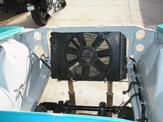
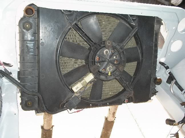
Is that the taurus 2 speed fan and shroud?
It looks to me that you could have gotten away with a flatter style 14" fan. (you know... the kind held on by zipties?)
No, it is the radiator, 2 speed fan and shroud from a Fiero. The Fiero has two styles of fan motor and this is the thinner one by a long shot. If you look at the pictures again you will see that there are 2 bolts at the top and 2 bolts at the bottom of the shroud that bolt it to the radiator, this holds it very securely and because I trimmed down the shroud the fan actualy sits closer to the radiator than it did stock. I had thought about using a different fan like the one that zip ties in place but I like having the shroud on it and I was not happy with the last fan I had that zip tied to the radiator.
Dragonfly
-
wow .. you have a C/F hood and you painted it greeen?!
Yep... the car is not exactly a sleeper but I did not want to let on quite how modified it is. I also painted the CF rear hatch green.
Dragonfly
-
I'm with the majority here... 944 wanna be. I have at least one picture of a Z at home that someone tried to make look like a 911 when I get home I will see if I can dig up the pic and post it.
Dragonfly
-
may i ask what you cleaned those up with? sandblast with aluminum oxide pellets or something?
Very good guess... I did use a sandblaster with an agressive sand in it, but to protect the machined bearing perches on the inside I left them coated with grease which of course created something like gritty mud when I was done. So the next step was to wipe out as much of the grease and sand as I could with some old rags then I put the hubs in my parts washer and scrubbed them with both a nylon brush and a metal brush. The next step was to wipe them down with clean rags and blow them dry with dry air from my compressor, after that I wire wheeled them to insure there was no flash rust starting to form then I masked and painted.
Dragonfly
-
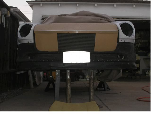
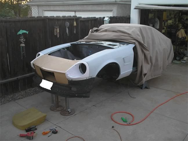
Because I was having clearance issues between my electric fan and my electric water pump I decided to install my radiator and fan at an angle.
If you look closely you can see the aluminum and rubber brackets I made to hold the bottom of the radiator in place.
In this picture you can see the custom steel and rubber brackets I made to hold the top of the radiator in place.
From the front with the hood on the car.
From the engine compartment with the hood on the car.
Distance from front side of motor mount bolt to fan shroud (14").
Distance from front side of motor mount bolt to balancer (13").
As you can see from the measurements I have 1" of clearance between the fan shroud and the balancer, what you can not see in these pictures is that I now have 2" of clearance between the fan motor and the electric water pump.
This is an older picture from my original mock up that shows part of my cardboard template for the aluminum shrouding for the radiator and fan.
In this picture I do not have the "box" portion of the mock up made up yet but when I am done all the air will be forced through the radiator.
Dragonfly
-
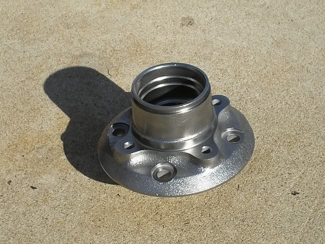
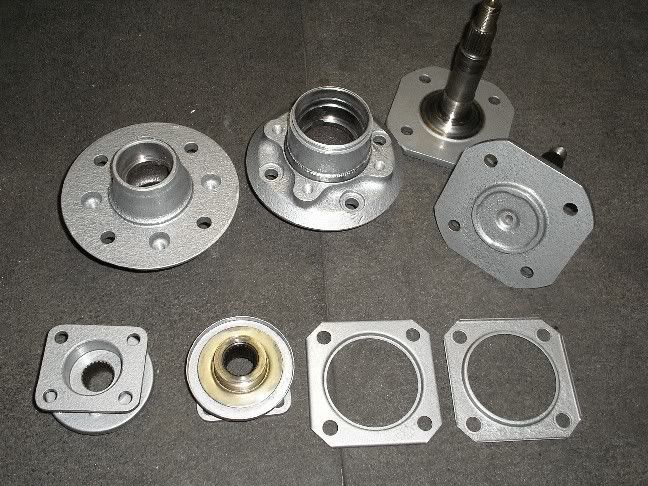
I should be recieving my wheel studs in a couple of days but while waiting on them to arrive I went ahead and cleaned up and painted my hubs and axles.
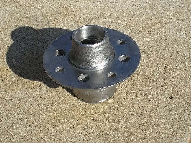
Here is one of my front hubs after cleaning and prior to masking for paint.
The other side of the same hub.
Here are the hubs, axles and flanges after painting.
I am also waiting on my new bearings to arrive. After everything gets here I will be assembling everything and taking more pictures.
Dragonfy
-
How about this:
Are there any safety, regulation, or any other issues that anybody can think of that would make bolting them straight to the floor pan a bad idea? I would do it very securely, of course.
As long as your floor pans are in good condition with no rust I am not aware of any problems. I would suggest that you back up the bolts with a large washer or metal plate to help disperse the load in the case of an accident or just slamming the seats back and forth. I am running Momo seats and I had to drill new mounting holes.
Dragonfly
-
I was increadibly lucky when I had a head bolt break off on me... it looked very similar to the picture you have and I was going to take the whole thing to a machine shop but I decided since I had a pair of vice grips handy I would give them a try before pulling the engine and the bolt came right out. If you don't get as lucky as me I can say that melting wax as described by Doc is one of the best ways out there to get a stuck bolt out, I have used that trick many times over the years and it has always worked.
Dragonfly
-
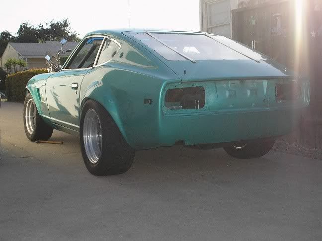
Before the flares were put on. I had a couple of years of driving with the tires sticking out about 2-1/2 to 3 inches beyond the fender and in that time I had the one fixit ticket and all I did for that was put a cheesy little mud flap behind the rear tires and got it signed off... That is also when I decided that I should serously consider getting some flares.
Dragonfly
-
Oh man, im glad I didnt get those without our flares on yet. Cops would pull us over and ticket us in no time around here for sticking out so far.
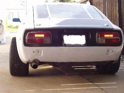
I like the glass hatch!
Here is a much more recent picture.
The rear hatch is actualy CF and made by Beta Motorsports (John Coffee). I only got pulled over once for those tires on my car and got a fixit ticket.
Dragonfly
-
My brother has these on his mustang maybe i'll borrow them for a few runs...
except he has 275/50/15 bfg drag radials
If you are curious here is what 275/50/15 NITTO drag radials look like on my Z. You can see them a little bit in the avitar as well.
I am not sure what the offset is but I have close to one inch clearance to my coilovers. BTW the rims are 10 inches wide.
Dragonfly
-
No problem.
Were you going to go with the shorter stock replacments for the RX7, or the ARPs?
I am going with the ARP's, those were the ones that I wanted in the first place. I decided that if they are just to long for me I will go over to the ZRaceProducts shop chuck them up in the lathe make a quick start nose for them as well as cutting them down to the length I want.
DRTY260Z I will check my reciepts later and list the cost on everything.
Dragonfly
-
Thanks for the compliments guys. I am ordering new wheel studs all the way around and after I get them I will take and post pictures of the brakes installed on the car.
P.S. Thanks jmortensen the tip on the wheel studs.
Dragonfly


Pics of my new brakes
in Brakes, Wheels, Suspension and Chassis
Posted
The car is a 72' and here is a link to a picture and some info on the adapters. http://cgi.ebay.com/ebaymotors/ws/eBayISAPI.dll?ViewItem&refid=store&viewitem=&item=160071443932
Dragonfly