darom
Members-
Posts
135 -
Joined
-
Last visited
-
Days Won
6
Content Type
Profiles
Forums
Blogs
Events
Gallery
Downloads
Store
Everything posted by darom
-
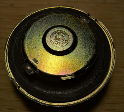
I believe this is the part: https://www.autohausaz.com/pn/16111103603 or here: https://www.fcpeuro.com/products/bmw-fuel-tank-cap-2002-2002tii-1602-16111103603-1
-
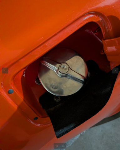
I installed 10-12 years ago, the fuel prices were high and there was some gas theft going on in my area. I needed a lockable gas cap
-
Sorry about the confusion. I bought a 2002 bmw gas cap which I installed on my '76 280z.
-
I bought a gas cap for a 2002 bmw for my 280z (MSA used to sell them, it is showing out of stock: https://www.thezstore.com/product/4445/locking-gas-cap-70-76-240z-260z-280z ) The cap fits tight. Not sure if this is something that will work for your racing events.
-
I removed the cylinder head, N47, didn't find any torn pieces of the gasket. After ordering a new set of valve springs and valve seals from zcardepot, I took the head to the machine shop.
-
My current issue is with leaking oil and coolant. My head gasket is leaking coolant - this is between cylinder 1 and 2 on the RH side. I can see the coolant right at the edge of the engine/cyl head. When I installed the new timing cover, my head gasket got torn at the top. I made a gasket and used some aerobic silicone. The oil is leaking a little on both sides. The plan is to remove the cylinder head, take it to the shop to get it reconditioned (new stem seals, check the springs etc), put a new set of ARP stud fasteners with an OEM gasket. The new gasket will also stop, hopefully, the leak at the top of the timing cover. I checked the prices on the Nissan head bolts - they are in the hundreds now. Not sure what happened. The MSA is basically recommending to go cheaper ARP route (which used to cost more in the past, now it is reverse).
-
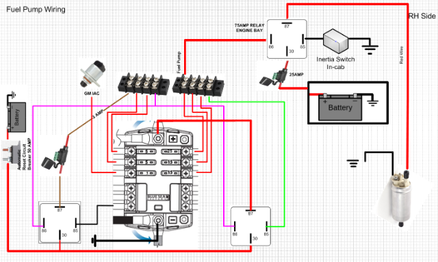
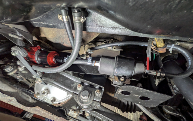
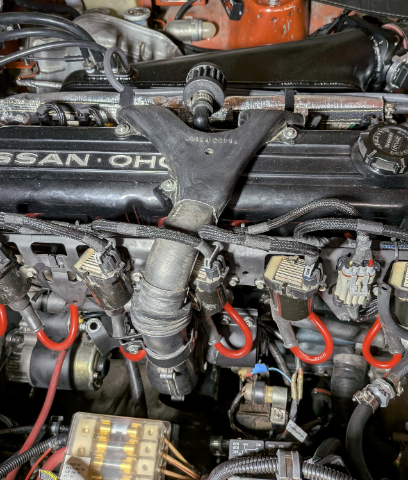
I also decided to re-address the lean condition on hot restarts. When it happens, the fuel pressure would bounce around, 18 - 22 psi. The FPR is set to 37-38 psi (w/o vacuum), at idle normal psi is around 31-32 psi with the vacuum attached. The FPR is an Aeromotive unit. Started with the fuel pump's (Walbro 255) voltage. 1. My original design - battery -> circuit breaker -> microsquirt's fuel pump relay -> main relay -> 30AMP relay (Inertia switch) -> Fuel Pump All wiring is 14 gauge. The voltage delta between the battery's and the fuel pump's was 1.5 Volts! 2. Re-did the ground - dedicated negative to the back panel's ground point where the tail lights get grounded. The delta was 1.2 Volts. 3. Installed a dedicated FP relay in the engine bay (Tyco 75Amp, with a 25amp fuse), with direct run to the fuel pump. The microsquirt's relay provides a trigger on post 86, inertia switch (in cabin) - ground. The delta is 0.3 Volts. Here is a diagram: Another possible issue might be related to the pre-pump's G3 Fram's filter being too restrictive (40 micron). Installed a 100 micron pre-filter: The pump is very quiet. The hot restart ends up with 14-15 AFRs for about 40 seconds, then it scales back to my pre-configured 13.5 at idle. I don't see a lot of fuel pressure fluctuations any more. As a precaution I added a 1979's 'hair dryer' to cool my injectors. I found it at a junk yard. I am using a time relay board which is set for 15 minutes. When I park the car, I can engage it from inside. I will test it on a hot day:
-
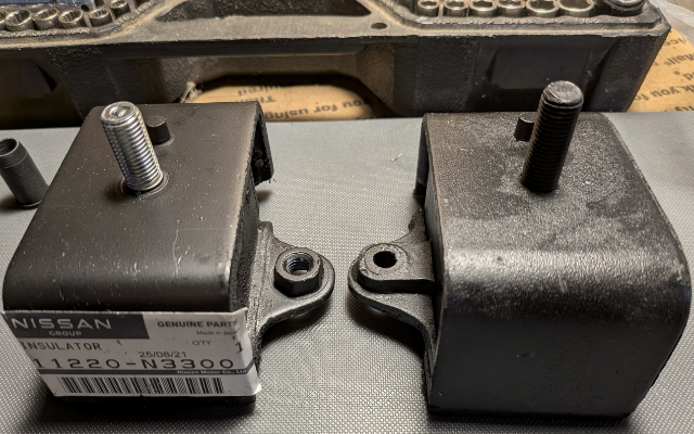
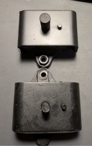
Installed a set of OEM engine mounts. They are still available, the cheapest ones are shipped from Japan (ebay source), about $120 total. Originally, I figured I would save some money and ordered a $20 special for a pair + s&h. Then I found some posts on classiczcars about their poor fitment, SAE threads (not with the pair I purchased), misaligned locating pins etc. Here are some pictures for comparison. The center bolt is longer on the after market one: The locating pin is way off: The OEM mounts fit like a glove, no issues.
-
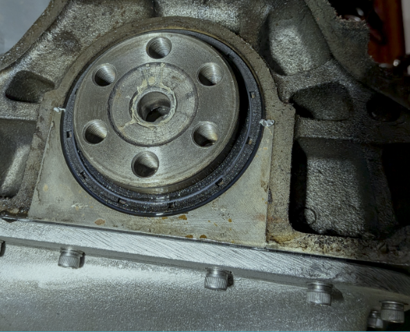
It was the rear main seal leaking, I removed the transmission and could clearly see the oil around the seal:
-
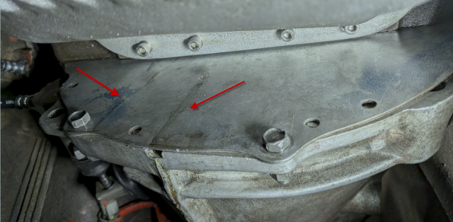
After priming the engine oil and starting/warming up the car, there is a small leak around the rear main seal. It is either my side seals or the rear main. Considering how easy it is to bump the seal while installing the rear cap, I wouldn't be surprised. I guess it is time for a tranny drop operation. I will check with my endoscope.
-
Hi CalZ, It is https://www.amayama.com/en
-
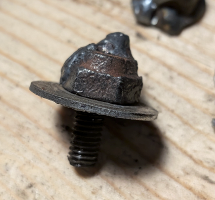
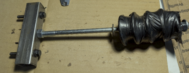
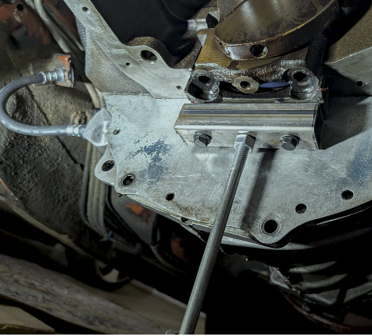
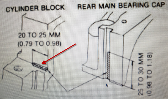
I have been dealing with some consistent oil leaks around tranny/engine block, and front RH lower part of the timing cover. The worst leaks would happen when the car was parked at an incline. I replaced my original TC with a new unit (there is a company selling them from Japan), total shipped was around $100. My original cover had some stripped threads. The water pump's long 80mm M6 bolt (at 10 o'clock) was broken inside the block. I had to weld a washer with a nut to remove it. The oil pan gasket that I sealed 10 years before, with permatex gray/gasket sandwich started leaking on the RH side. The removal of it was a major pain. I decided to get an aluminum pan from AZC since I am considering a turbo upgrade in the future and that pan already has provisions for the oil temp sensor and turbo oil return fitting (I went with the 8AN fitting). The pan is solid and straight. I 'glued' the cork oil pan gasket with the permatex black to the pan to prevent the gasket movement while I was installing the pan. My hope is the fact the pan is a solid aluminum piece, there is not going to be much flexing/worrying about dimpled surfaces etc. While the pan was off, I also replaced the rear main side seals. Mine looked old/brittle when I removed the rear main cap and inspected them. I tried pulling the metal inserts with a pair of needle nose pliers, but they were stuck really good. The rear cap was removed using an improvised slide hammer (the taped part is a bunch of heavy washers): It took about 10 minutes to remove the cap: I didn't see any sealant in the corners in my engine. I am hoping this might explain the oil leaks. Per FSM: Before the cap installation, I put a bead of gray ultra in the corners on each side. The side seals got a coat of gray as well when I inserted them. The rear main cap was in a freezer. Its installation went smoothly. I haven't filled the engine with oil/coolant yet. If I see more of oil leaks around the rear part of the engine/tranny, I would probably pull the transmission and replace the rear main seal along with the transmission's gasket/seals.
-
Hi @Mike280zx, if you don't get answers on this forum, i'd advise to post on https://www.msextra.com/forums/index.php Regards and good luck with your project.
-
Thanks, Tom, will add a little more fuel. I noticed my cold -> warm cycle follows a pretty predictable AFRs curve per the table and my manual tuning I did at idle a while back (I was aiming for 13.5-13.7). Things go out of wack somewhat when I restart a hot engine, the AFRs are leaner until they stabilize later on.
-
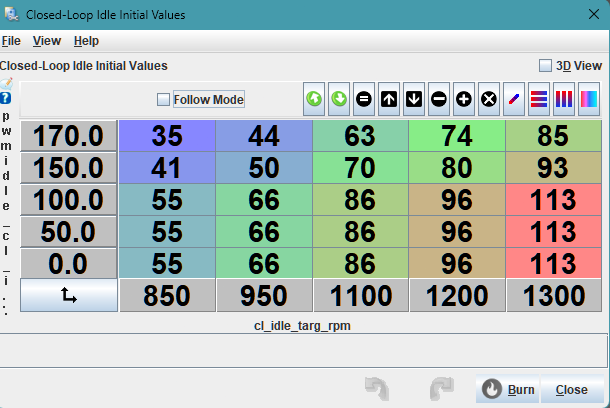
Update: Today I worked on correctly setting up the initial target RPM table. Took two readings per each rpm step, in my case, 850, 950, 1100, 1200 and 1300, when the car was semi-warm and hot. Then added another 10 percent per: https://www.diyautotune.com/support/closed-loop-idle-pwm/ Then from 100 to 170, interpolated vertically. Since I didn't know what steps would be at lower temps, left them the same at the bottom: I switched to using CLT table (not MAT) since I am still clueless where I can find it (unless TS uses the same table for both and it will be just different temp ranges there). I also noticed at hot restart, the AFRs are very lean, 15-16 range due to the injectors getting heat soaked. Searched on the msextra, found some posts about guys using a band-aid fix by adding ASE and taper at higher temperature. I experimented with mine and added some: It does help somewhat in the beginning. I added EGO correction of 8 percent above 800 rpms. This helps as well, and my AFRs get back to normal range. I am posting my updated tune, plus the idle log. I haven't taken the car for a test drive yet. 2025-07-06-v106.msq 2025-07-06_10.40.07.mlg
-
Hi Tom! 1. I ordered another TPS sensor (different vendor) to test. I also noticed that it is not 100 percent stable. I am using the sensor ground for it per microsquirt manual and the 5V feed. My throttle blade is completely closed, the spring is strong in this Protunerz' throttle body. I do have a throttle cable slack. 2. I think what is happening at 16.833, is that for -200 rpm correction per the 'Idle Adaptive Advance Timing' table, it will kick 6 degrees of timing. My running RPMs are 996, when the target is 1200. So the ECU is adding 6 degrees to raise the RPMs. When the RPM of 1200 is matched, for ex., at 27.366sec, the correction advance is almost at 0 degrees, 0.6 actually. 3. At 26 seconds, i was backing out of the garage in reverse, with almost no TPS input. No sure what is happening here either. I also see a -280 RPMdot that follows. 4. At 93sec, there is a TPSdot of 14, maybe this is why my AE is enabled? My target RPM is 1183, the running RPM is 972, I see the Idle Correction Advance is adding another 6 degrees. I am wondering if I should move from 6 to 3 degrees max for CLI control? It might be too much of a change to adjust the RPMs? I will try that and will make another log. Overall, the CLI is the most confusing part for me. When it finally started working (kind of), it surely made my day :-) Appreciate you taking your time checking out my progress! I do have a few questions for you - per your tune: a. you have Shift Settings -> Leave Valve Closed Above:(rps) - 7,000, For this number of seconds - 0. Basically, you don't want the IAC valve to close at all? Any benefit from this setting? b. you are using the table for CLT in the CLI Settings (Use CLT or MAT In Table Lookup). Do you have any heat soaking issues? I read some posts where it was advised to use the MAT table. Any other benefits? Should I use the CLT table as well? I asked the question on the msextra forum why the ECU still checks the CLT table, but no one has responded yet: https://www.msextra.com/forums/viewtopic.php?t=82151&sid=ccd10333b5cfba1911eaded17a655060 Thanks! Den
-
Update: I figured out why my RPMs were so low and the IAC wasn't adjusting its steps. My TPS in the Closed-Loop Idle PID Activation Settings, was set at 0.8. The actual TPS was 1.1 that day which meant that the CLI would never kick in when I was sitting in the car at idle. I re-calibrated it and decided to play it safe and set at 1.5. Today the car's CLI worked as intended. I am still dealing with wonky IAC which can be at steps 90 and barely allowing any air in. Also, I noticed that even if I select the MAT table to be used for reference, the ECU was still looking up the CLT settings. I posted this question on the msextra site, maybe it is a code glitch or this is how they designed it or I am missing another table. I might just use the CLT reference table and call it a day. I am posting the updated tune and the drive log. 2025-07-03_12.14.29-drive.mlg 2025-07-03-v104.msq
-
Update: replaced the mustache bar bushings, re-torqued the strut lock nuts. I don't hear any more banging noises now. Still not sure what fixed it though. When I was checking my rear Bilsteins with springs compressed, I didn't feel any extra movements to give me that noise. I also swapped my master, slave clutch cylinders and clutch hydraulic hose. The old ones had some 'brake fluid sludge' inside from the internal leakage. I adjusted the clutch pedal at 8 inches (i have a carpet/sound insulation), the master cylinder rod of the replacement unit was the same length, no need for an extra nut. I could put the pedal at the max height (over 9.5 in) and the rod was still good. The free pedal travel is within specs, 15 mm. I was observing the operation of the slave with my $20 endoscope, 15 mm of the clutch pedal before the slave starts its movement. The clutch fork throw is half an inch (12.5 mm). I could push the slave's rod back towards the front, the rod gets back to its self-adjusting position. I did some searching - it sounds like 15 mm is a better number. My reverse and 5th get engaged without grinding noise and without any difficulty. The clutch operation is smooth. I used Rockauto's Luk's: LMC245 and LSC199 parts. Appreciate your guys' help. After fiddling with my closed-loop idle, I am still chasing my tail. I posted a thread on the msextra.com forum at: https://www.msextra.com/forums/viewtopic.php?t=82151 The RPMs get dropped very low, the ECU is not commanding enough steps for my IAC (or it is telling to give, for ex., 60 steps with not much difference). The car is driveable, but with rpms sometimes hitting low 300-400s, which is not good (CLI is not even running when it happens). Here is my updated tune and drive logs if anyone wants to take a peek. Thanks, Den 2025-06-29-v102.msq 2025-06-29-cold-start.mlg
-
Cool, thanks AtoZ! I will check the rod length, if needed I will weld a nut to extend it a little.
-
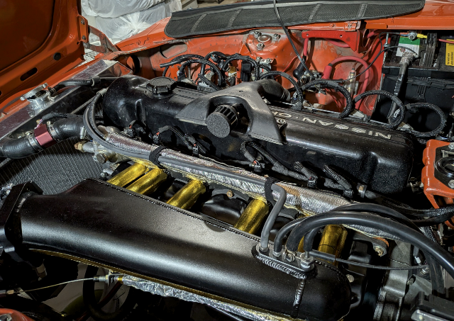
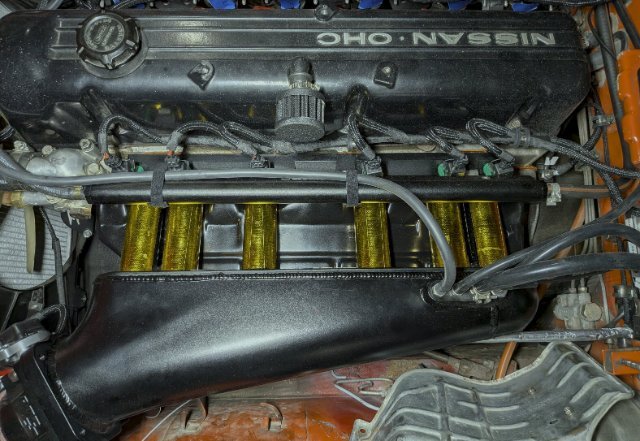
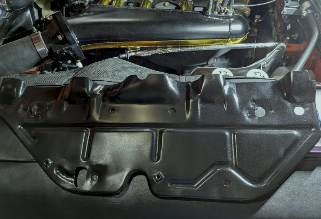
I set up the closed loop idle finally. This is the one of the best things since the invention of sliced bread. I still need to tune it, I will post my updated tune. I took the car for a test drive and noticed annoying loud rear-end noises going over any crack and pothole on the road. It is not clunking. My reverse gear is also hard to engage, I ordered a new clutch master/slave - it looks like the slave doesn't extend fully its rod, I think my clutch is dragging and my clutch pedal is out of adjustment. I will be replacing my mustache bar bushings and re-checking the torque of the locking strut nuts in the rear. Meanwhile, I decided to address my heat soaking issues with the intake, fuel rail and injectors. I found my old heat shield, bend it to contour the intake/exhaust ports and installed it. I checked with the remote temp gun, there is a 30F difference now (fuel rail/injectors were showing 170F):
-
I installed the new IAC, it seals the air bypass much better. It has a pointed tip (the Grand Am IAC is on the left, the right model comes with the Protunerz intake: I tried using Tom's tune idle air valve settings/steps (4-7-1, time steps + initial time step size + minimum steps to move), it worked on the bench in the beginning, but strangely once in the car, it refused to move and was stuck in one position. I put back my original (3-5-3) steps and it started moving. I am keeping 'Always on' setting as it works more predictably. I have a general question about these steps considering dozens of other combinations people use with their MS boards. Assuming the valve is the same, one car uses the Megasquirt board (dedicated IAC outputs) and another has a Microsquirt with the EFI Source's IAC stepper adapter (https://www.efisource.com/wp/shop/microsquirt-iac-stepper-adapter/), will the valve take the same steps in TunerStudio? I also tried both Homing Direction 'Open' and 'Closed'. The 'Closed' seemed to work better. The idle is stable. I found a set of informative YT videos at: https://www.youtube.com/watch?v=z43YPcDGQEQ on setting up the CLI (closed-loop idle) and will play around with it this week.
-
Thanks for the tune! I ordered a new IAC mentioned on the efi web site, for 1992 Grand Am 3.3L V6 model, walker products 21591012 (Tom, appreciate the reference). It has a different sharp pointed tip vs the ones I have (mushroom shaped). My IAC can barely control the idle, letting a lot of air by (poor seating position inside the PTZ's intake). It is also sometimes unpredictable - one day it will set the idle at 900ish, the other - over a 1000 rpm. I will update the thread once I install it.
-
Thanks, Tom. The idle is smooth/predictable, without any oscillation. 1. WUE is changed per your config. I set it at 175F. 2. I left the EGO correction above 1300 rpm since my original thought was to prevent it from making changes to my VEs keeping a specific AFR there (13.5 - I am running batch injection, engine runs great with a healthy vacuum). Should I lower the EGO rpm limit from 1300 to 1100? I am still fiddling with the IAC stepper to lower my initial warmup idle. It jumps to 1600 rpm, I might move it to 1300 rpm by cutting the number of stepper steps. 3. Adjusted my ASE settings (percent/taper) I noticed that when the engine is hot, and I restart, my AFR is about 14.7-15 during the first 30-45 seconds. Then it goes back to my 13.5-13.9. Should I leave it alone or instead (this is my OCD is 'talking'), increase my ASE percent adder to a higher number to add a little more fuel (for ex., at 175F, from 9 to 15)? I will take the car for a test drive this week-end, will do a data log. Appreciate your suggestions! 2025-05-27-ASE-changes.msq 2025-05-27_17.45.45-hot-restart.mlg 2025-05-27_17.33.07-cold-start.mlg
-
Thanks Tom for your recommendations. 1. sync loss - I noticed with my microsquirt (plus a few more guys on youtube), if I apply 'Burn' while the engine is idling, it would stumble/recover and will generate 1 sync loss error. I checked my driving log and didn't see any sync losses there. I am attaching my warm idle log, it doesn't show any errors either since I didn't apply any corrections. This stumble/burn issue might be related to microsquirt ECU limitations, I am not sure. 2. I re-adjusted my TPS while observing the throttle blade. Now I have 545 points in my throttle movement. The throttle blade is closed. 3. I set timing from 14.2 to 17 degrees. It looks like my engine doesn't mind, runs stable. 4. thanks for finding this TPS WOT curve - copied your settings. 5. my GM MAP sensor is showing 40 - 41 kPa at idle. I am at 873 feet in WI, which computes to 17.51 inHg. I got my mechanical vacuum gauge to double check - it was showing between 17 and 17.5 inHg (approximation). I feel much better. : -) 6. the lock/unlock option for sensors - I totally missed this one, it is locked now. I set the Top Dead Center a while back and confirmed it with my timing light (using 'Fixed' timing option in TunerStudio). I also re-adjusted my IAC valve steps per your tune. I will keep it as open-loop for now. I will do a data log for the car when the engine is cold. Appreciate the help! Den 2025-05-25_warm.mlg 2025-05-25-17degrees-idle.msq
-
Hi @Datsunpowers Tom! I appreciate your time posting your IAC setup here. I wish Protunerz would grind the sharp edges at their factory. I talked to them, they are aware of all this whistling business with their intakes. They are great guys and I got quick tech question responses from them. But the noise is an embarrassment to a pricey car part. I have a few questions for you: - Do you set up your throttle blade to be completely closed and then configure your IAC to provide additional air to get your target 750 rpm? I went over this subject on a msextra forum as well, and it appears there are 2 ways to do it. One is to open the blade a little and IAC completely closed at idle. Another - the throttle blade is physically closed and IAC is providing air for idling target speed. I went with the 1st option, since I couldn't get my IAC to provide predictable behavior. One day it would be idling at 900 rpms, next day - 800-850 rpm, another - around 1000 rpm. I figured the IAC's min steps and step size needed to be played with and per Madcaw's advice, I left it on 'Always On'. This helped somewhat. I also bought another IAC for a 1999 Camaro V8 (Ultra-Power AC162) to test (10$ special from Rockauto), but I haven't installed it yet. I suspect my IAC is not completely sealing the opening, thus these fluctuations. - Open-loop vs closed-loop question I removed my a/c a while back, and I have a 5-speed. I thought the closed-loop idle control is suited for the cars with big electrical loads (like electric fans, a/c compressor kicking in) or an automatic transmission. I have a belt driven fan. All my headlights are converted to using relays. I set up the open-loop since it was the easiest option. Would you recommend for my car to switch to the closed-loop idle control? If you don't mind checking my tune/idle and a driving log, I'd appreciate it. What are your car's specs? Can you share your tune? Thanks! Den 2025-05-18_13.51.43.mlg 2025-05-18-adj-IAC.msq 2025-05-10_11.12.19-driving.mlg
