darom
-
Posts
137 -
Joined
-
Last visited
-
Days Won
7
Content Type
Profiles
Forums
Blogs
Events
Gallery
Downloads
Store
Everything posted by darom
-
Thanks Tom for your recommendations. 1. sync loss - I noticed with my microsquirt (plus a few more guys on youtube), if I apply 'Burn' while the engine is idling, it would stumble/recover and will generate 1 sync loss error. I checked my driving log and didn't see any sync losses there. I am attaching my warm idle log, it doesn't show any errors either since I didn't apply any corrections. This stumble/burn issue might be related to microsquirt ECU limitations, I am not sure. 2. I re-adjusted my TPS while observing the throttle blade. Now I have 545 points in my throttle movement. The throttle blade is closed. 3. I set timing from 14.2 to 17 degrees. It looks like my engine doesn't mind, runs stable. 4. thanks for finding this TPS WOT curve - copied your settings. 5. my GM MAP sensor is showing 40 - 41 kPa at idle. I am at 873 feet in WI, which computes to 17.51 inHg. I got my mechanical vacuum gauge to double check - it was showing between 17 and 17.5 inHg (approximation). I feel much better. : -) 6. the lock/unlock option for sensors - I totally missed this one, it is locked now. I set the Top Dead Center a while back and confirmed it with my timing light (using 'Fixed' timing option in TunerStudio). I also re-adjusted my IAC valve steps per your tune. I will keep it as open-loop for now. I will do a data log for the car when the engine is cold. Appreciate the help! Den 2025-05-25_warm.mlg 2025-05-25-17degrees-idle.msq
-
Hi @Datsunpowers Tom! I appreciate your time posting your IAC setup here. I wish Protunerz would grind the sharp edges at their factory. I talked to them, they are aware of all this whistling business with their intakes. They are great guys and I got quick tech question responses from them. But the noise is an embarrassment to a pricey car part. I have a few questions for you: - Do you set up your throttle blade to be completely closed and then configure your IAC to provide additional air to get your target 750 rpm? I went over this subject on a msextra forum as well, and it appears there are 2 ways to do it. One is to open the blade a little and IAC completely closed at idle. Another - the throttle blade is physically closed and IAC is providing air for idling target speed. I went with the 1st option, since I couldn't get my IAC to provide predictable behavior. One day it would be idling at 900 rpms, next day - 800-850 rpm, another - around 1000 rpm. I figured the IAC's min steps and step size needed to be played with and per Madcaw's advice, I left it on 'Always On'. This helped somewhat. I also bought another IAC for a 1999 Camaro V8 (Ultra-Power AC162) to test (10$ special from Rockauto), but I haven't installed it yet. I suspect my IAC is not completely sealing the opening, thus these fluctuations. - Open-loop vs closed-loop question I removed my a/c a while back, and I have a 5-speed. I thought the closed-loop idle control is suited for the cars with big electrical loads (like electric fans, a/c compressor kicking in) or an automatic transmission. I have a belt driven fan. All my headlights are converted to using relays. I set up the open-loop since it was the easiest option. Would you recommend for my car to switch to the closed-loop idle control? If you don't mind checking my tune/idle and a driving log, I'd appreciate it. What are your car's specs? Can you share your tune? Thanks! Den 2025-05-18_13.51.43.mlg 2025-05-18-adj-IAC.msq 2025-05-10_11.12.19-driving.mlg
-
Thanks, calZ. I switched my throttle cable at the TB from the very top position to the bottom one. I also tried the middle one (not much success there). The car feels normal again.

-
Update: 12V for HALL sensor did the trick. I don't see any sync issues in the logs. Guys, I wanted to pick your brain on the throttle cable / TPS / accel. pedal adjustment (Protunerz 75mm throttle body). The way I did the adjustment is to press the pedal to the floor (full throttle) and make sure the throttle body blade was wide open. At this point, TPS gets configured in microsquirt at rest/open, all is good. My SX240 TPS is allowing the blade operation from closed to open position. However, I noticed that my pedal is super sensitive now. Slight press creates a sudden acceleration - I have to re-learn my clutch 'feel' again, I am afraid to burn it. For ex., checking the logs I am seeing: RPM TPS% 2925 27.4 3719 30.9 3282 20.9 2620 21.5 3616 25.9 3485 18.9 3395 26.8 Do these numbers look ok? @madkaw Steve, do you mind sharing how you adjusted your throttle cable? I am wondering if the new size of the throttle body (75mm vs the stock 60mm) is also throwing a wrench here. I re-used my stock accel pedal. Thanks.
-
Thanks. My only wish is that BlueSea relay box had extra 2 fuse protected circuits.
-
Hi Weber, this forum is a little slow I just went through the microsquirt installation on my 76. Here is the thread showing the location for the MS (RH side) and the relay board (LH): I separated 12V relay board wires from the ECU's to avoid any interference. I also didn't want to put the MS board inside the engine bay. Regards, Den
-
I swapped the HALL sensor's 5 vrf with a 12v feed. This time all the sync losses are of my doing. For ex., adjusting the AE or WUE tables and exiting the windows, causes the ECU/engine stumble (almost like burning the changes), which generates "a reason 2" sync loss. It might be a psychological effect on me, but the car seems to idle smoother with a 12v feed to the HALL sensor. I managed to lower the idle by putting 14.x timing degrees. Thanks to everyone who helped with my issues! Should I enable the Closed Loop idle now? I don't mind keeping the Open Loop, I am just looking for any benefits of CL vs OL. 2024-11-23_15.22.20.mlg 2024-11-23-before-VE-smoothing-out.msq
-
The shield is grounded at the microsquirt's sensor ground location. I might try the 12v feed to the HALL sensor. I recorded two logs while doing a warm-up enrichment autotune tonight. The 1st one picked up only 2 sync losses, the 2nd - 11. I'd admit I was committing the burn to ECU commands which I noticed causing some of the sync losses. But not all 11 of them though. I also don't see any sync loss 'consequences' on my engine running. 2024-11-22_16.45.52.mlg 2024-11-22_16.53.40.mlg 2024-11-22-adjusted-ASE-taper.msq
-
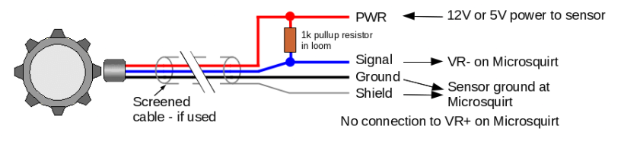
Yes, thanks. I am using a 1k pull-up resistor with the HALL sensor wire. I followed the msextra's microsquirt doc on its wiring. I also haven't played around with signal filtering in TS.
-
Thanks, Steve! I will put 4-5 min steps instead. I noticed that every day (here in WI, we were at 45-50F for the past 3 days), my engine startup/warmup bevaves differently. I had to fiddle with the VE table/timing to get a stable idle. It might explain this if my IAC is not predictable and can't keep its position. I have been doing some reading and it seems that 5v vref switch to a 12v feed for the HALL sensor most of time doesn't resolve a sync issue. I have an osilloscope and would try logging the HALL sensor's output. Would you recommend switching over to the closed loop idle mode or stay with the open loop? I have no a/c, the radiator fan is not electric.
-
Yesterday I drove the car with the autotune running. I started a thread on msextra about my sync loss issues at: idle/IAC question if someone has time to review my tune/datalog. Thanks
-
Hi guys, What should be my idle fuel pressure? I have been running a FPR set at 43 psi without vacuum attached, which translates to 35-36 psi at idle (440cc fuel injectors). Is this an ok FP for operating these injectors? I finally got my idle sorted out with the Open Loop mode. The IAC is a sob, makes annoying noises, and I don't trust it that it stays in the set position 100 percent (I set mine in Always On). The idle would occasionally dip accompanied with the IAC noise. I'd try getting another unit to test. Thanks! 2024-11-12-good-idle.msq
-
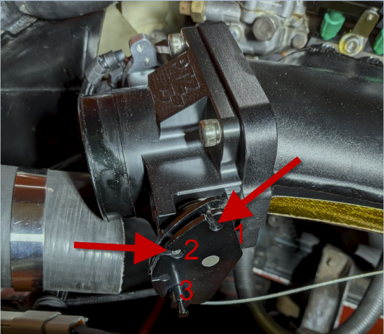
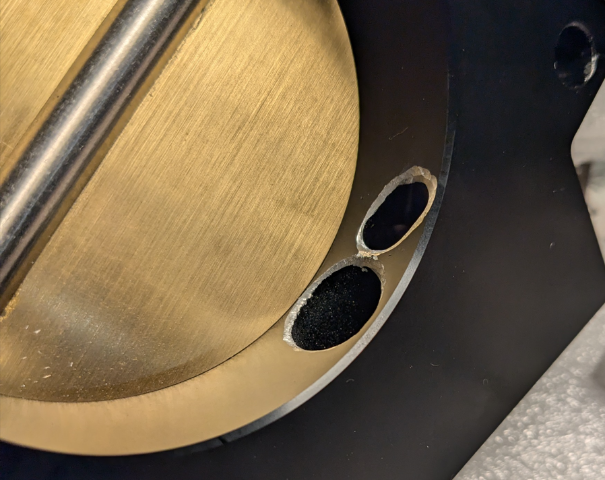
Protunerz got back to me and suggested dremeling the edges off in the throttle body. First I tested it while pointing my air compressor's nozzle at it and it made the annoying noise. Removed the throttle body and took sharp edges of openings with a dremel tool: It passed the air compressor test. After installing it, the noise is gone 80 percent, there is still some noise when the throttle blade opens up.
-
I found out that the IAC plug in my throttle body is actually leaking air, possibly causing this RPM increase. I sent an email to Pro Tunerz asking if this is intentional or if their plug should be sealing the opening 100 percent.
-
yes, same problem it seems with these intakes. I used a thin layer of Permatex Ultra Copper, the leak is stopped, i checked with my smoke leak detector. I fixed my timing table (more conservative numbers), re-calculated my Bosch 0280155968 injectors flow at 36 psi (without vacuum it is at 43 psi), and re-generated my VE table using the built-in TS calculator. 43.5 PSI (3 BAR) 430 cc / min = 41 lb / h Calculation: old/original fuel pressure = 43.5 New Fuel Pressure = 36 Size of Fuel Injector in lb/hr = 41 New flow/Size of Fuel Injector = 37.298 lb/hr or 392.01 cc/min The IAC is disabled, the valve opening is plugged. I can't re-check the idle startup with engine cold at the moment, but when warmed-up, I can't get the RPMs lower than 1.5-2k. The only air leak is at the throttle body with the blade which is barely open (if I close it more, the car dies). The engine's vacuum is at 15-16 at the 1500 rpm. My valve cover vents the gases via a small filter. The PCV valve is connected and operational. If someone has time to review my tune with a datalog and tune for any issues, I'd appreciate it. Should I proceed with turning my IAC on at this point? Or I need to test the cold startup before going with the IAC enabled? Thanks. PS With the throttle blade barely open, the car is making a loud annoying whistling noise. With IAC installed, the blade will be completely closed and this nonsense should stop, I hope. CurrentTune.msq 2024-10-27-no-IAC-VE-inj-changed-calculated-flow-7.mlg
-
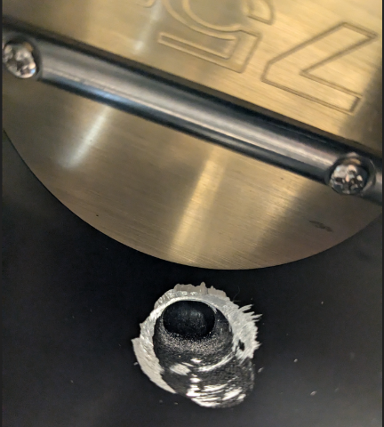
Replaced the MAP sensor, it is properly showing the kpas now. I have a bad air leak around cylinder 1, protunerz intake didn't seal the gasket. I did install it following the torque specs and order. While running, the air leak was audibly noticeable. I removed the intake, and didn't see any warpage. Ordered a new gasket. With GM IAC installed and in a closed position, the throttle body is making high pitched whistling noise. I guess the shape of the opening for the valve makes this bad harmonics issue. I also noticed my fuel pressure was around 50 psi. Adjusted the FPR, it is around 40-43 psi now.
-
Sounds good, thanks Steve. For now I will build a conservative timing table with max 36-38 degrees. I've been messing with my GM IAC I got from Protunerz. Managed to catapult the pintle into oblivion a few times. I didn't realize there is no stop. My max homing/closed/moving is at 160 steps. The IAC properly extends and stops at whatever CLT temperature is at. If I set the IAC at always on/hold current, it is making high pitched annoying noise. I will leave it at 'Moving' for now. I attached a fused 12V supply to it without my car running. What I _couldn't do_ is to use the 'Idle Warmup Duty' and put the max 160 steps in the 60-80F range to make the IAC completely close. Not sure, if this is because the car is not operational?
-
Great, thanks!
-
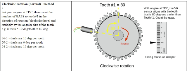
Thanks, NewZed. Appreciate your input. I did arrive at the same conclusion about the cam timing finally - two different things. Appreciate confirming it. I was way overthinking it lol. I think I finally nailed the initial timing config using 0 commanded degrees in the Fixed Timing section of the TunerStudio. I set 60 degrees in the 36:1 section, tooth #1 Angle (deg BTDC), which confirms Chickenman's statement about counting the gaps times 10 degrees for 36 trigger wheels (I have 6 gaps, 60 degrees). If I count teeth, my hall sensor is pointed at the 7th tooth. Question: I checked some of the guys' tunes on this board (cyrgnus and madcaw's) being curious about their total timing on their engines, and most of them have 41-43 degrees by 3000 rpms. I have a stock n/a engine with a N47 head, should i go with a more conservative number like 36-38 degrees?
-
Found some posts suggesting to use 0 degree fixed timing, this way I am avoiding any issues with timing light/wasted spark results. I don't have any timing marks (-10 to 10) besides the timing pointer I got with the trigger wheel. Tested with 0 degrees fixed advance and 0 degrees cranking advanced using 2 timing lights (old school with a variable knob on the back and the modern electronic one set at 0), both showed the TDC. My 36:1 Tooth #1 Angle (deg BTDC) was set at 60 degrees.
-
I was able to run the car with 70 degrees trigger crank wheel, 10 fixed. With advance timing light set at 0 degrees, I was seeing synced timing marks. Now, back to the previous post about doubling the timing light to 20 degrees to check my timing? Is it needed or I am good to go? I turned off the fixed timing, the car ran very rich, stumbling. I realized my MAP sensor (intake mounted unit from a used LS1 vehicle) was not working, it was stuck on 100 kpa. I am going to get a GM wall mounted unit. Saga continues. Thanks! 2024-10-18-auto-timing.mlg
-
I re-read Chickenman's post here: and set my 36:1 to 70 degrees, fixed timing at 10, the advance timing light at 0 degrees, and I have the timing pointer properly synced with my balancer's timing mark. I am still looking for those 'missing' 4 degrees Found another thread on setting up initial timing here "Please note this is nothing to do with cam timing or mechanical advance etc. you can set these independent of the bottom end using a vernier pulley." I guess I was confusing 2 different things here. Per that poster's write-up, the advance (variable) timing light needs to be set at double degree setting due to the wasted spark mode. So if I am commanding 10 fixed, the light should be at 20 degrees.
-
Now I am overthinking the initial timing configuration. My hall sensor is pointed at the 7th tooth. I found some posts advising to count the gaps and official doc saying I have to count teeth. If I set my Tooth #1 Angle (deg BTDC) at 70*, and command 10* at fixed, my advance timing light is at 10* - I get sync between the pointer and my harmonic balancer mark. I am confused about my timing chain/cam sproket 4* advance that I did years ago. Can someone please tell me if I need to add these 4 degrees to the 70* to have a "real" 10 degrees since the ECU is not aware of the mechanical cam advancement? If I use 74 degress for 36:1, 10 degrees fixed, my advance timing light at 10 degrees, I am off my pointer/balancer mark. Appreciate your input. Thanks.
-
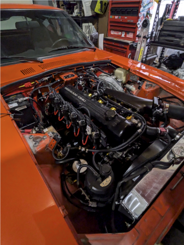
Morning, I ended up getting a 3" exhaust pipe tip and welding it to my stock air cleaner box: The relay board is installed, I left some fuses out while setting up the initial timing, the board will be covered with a stock ECU plastic cover: I installed the Microsquirt ECU on the passenger side to separate wires carrying 12V for inj/ign/WB etc from the relay board on the driver's side. This is a fabbed bracket: and in the installed position: Reflashed the stock ECU firmware with the msextra code, all sensors are calibrated (with the exception of the Spartan3 WB). The GM IAC will be worked on later while I am setting up idle. The coils passed the test from the TS. The LS2 truck coils are set at 3.5ms dwell per the manual.
-
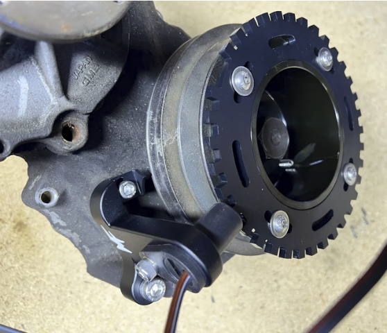
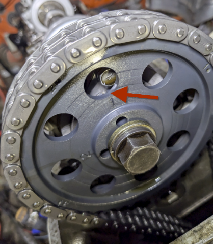
Forgot to mention that I had installed the MilkFab's trigger wheel that gets mounted on the 280z a/c harmonic balancer. This is their picture (I didn't take one): Last time I changed the timing chain (6 years) ago, I advanced it by 4 degrees, the notch is to the right of the cam gear mark: The MilkFab's instructions are calling for centering the sensor on the 6th tooth: "Adjust the trigger wheel while the mounting screws are loose to align the center of the sensor to the center of the 6th tooth if using the 36-1 wheel." I couldn't get the 6th tooth aligned (not enough adjustment), I could center it on the 7th tooth. I thought I had done something wrong. Searched the forums and found Chickenman's post (whose opinion I respect on this forum), who is recommending to use 7th or 8th tooth: "The missing Tooth should be 7 - 8 Teeth ahead of the sensor. Each Tooth = 10 degrees. So missing Tooth has to pass Crank sensor 70 to 80 degrees BEFORE TDC. This is very important. Re-position Crank wheel to get the missing Tooth ahead of Crank sensor by 7 to 8 teeth Minimum. " So my understanding is that my setting is at 60 degrees before TDS plus an additional 4 (physical cam advancement), 64 degrees. 36-1 wheel is a 10 degree per tooth. We need to count gaps. I placed mine on the 7th tooth, 6 gaps, i.e. 60 degrees (plus 'built-in 4 degree advance), 64 total. I hope I got it right.